
User Manual

SAVE THESE INSTRUCTIONS!
M2PD-4RD-A-_
- This product is ETL listed for indoor dry locations.
- This product can be installed to a 4" electrical box with
round plaster ring, or to an octagon electrical box.
- Minimum electrical box volume must be 6 cubic inches
(98 cubic centimeters).
- This product should be installed by a qualified electrician.
Installation Instructions for Monorail 2 Circuit Adjustable 4" Round Dual Power Feed Canopy
1
904-M2PD-4RD-A-04
IMPORTANT INFORMATION
1718 W. Fullerton Ave
Chicago, IL 60614
Tel: 773-770-1195
Fax: 773-935-5613
www.edgelighting.com
info@edgelighting.com
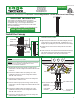
Install the Canopy
1: Loosen the four M4 set screws on the plastic disk with the
2mm Allen wrench provided.
2: Adjust the power feed wires to the desired height (from top
of the canopy to top of the Monorail - Illustrated as "H" in
diagram A) by pushing the power feed wires into the canopy.
3: Tighten the four M4 set screws firmly with the 2mm Allen
wrench.
4: Leave at least 6" of the power feed wires behind the canopy.
Trim off the excess power feed wires with a sharp cutter.
Strip 1/4" of insulation off of the power feed wires.
A
2MM ALLEN WRENCH
M4 SET
SCREW
POWER FEED
WIRES
PLASTIC DISK
2
4
H
B
HOT B1
HOT A1
COM 1
HOT B2
HOT A2
COM 2
SIDE WIRE
6
7
9
MIDDLE CONTACT WIRE
TOP CONTACT WIRE
CYLINDRICAL
CONNECTOR
LEFT POWER
HOUSING
RIGHT POWER
HOUSING
5
8
10
5: Starting with the left power housing, connect the top
contact wire to the low voltage wire marked "HOT A1" with
a wire nut.
6: Connect the middle contact wire (coming out of the
cylindrical connector) to the low voltage wire marked
"HOT B1" with a wire nut.
7: Connect the remaining side wire to the low voltage wire
marked "COM 1" with a wire nut.
8: Continue with the right power housing, connect the top
contact wire to the low voltage wire marked "HOT A2" with
a wire nut.
9: Connect the middle contact wire (coming out of the
cylindrical connector) to the low voltage wire marked
"HOT B2" with a wire nut.
10: Connect the remaining side wire to the low voltage wire
marked "COM 2" with a wire nut.
NOTE: Use the universal round crossbar (provided) if the electrical
box holes are not spaced 2-3/4" apart.
NOTE: The low voltage wires should be present in the electrical
box. Refer to the instructions provided with the remote
transformer to install the transformer.
1
3
CANOPY
© 2009 Edge Lighting. All Rights Reserved.