
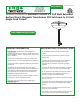
Owner's manual


HOUSING
SET SCREW
2
Install the Surface Mount Transformer
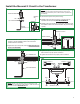
1: Loosen and remove the five M4 button head screws around
the transformer cover with the provided 2mm Allen wrench.
A
2:
from the set screw.
While holding the transformer, unhook the transformer cover
B
COVER
COVER
1
2MM ALLEN WRENCH
2
3: Remove the inside nut and washer to remove the crossbar
assembly. DO NOT DISASSEMBLE THE CROSSBAR
ASSEMBLY.
C
CROSSBAR
ASSEMBLY
WASHER
INSIDE NUT
3
D
#8-32 SCREW
CROSSBAR ASSEMBLY
NIPPLE
7
4
8
6
M4 BUTTON
HEAD SCREW
1
1
9
4: Connect one set of provided white and black extension wires
to the neutral and hot power wires coming from a switch
respectively with the wire nuts provided.
5: Connect the other set of provided white and brown extension
wires to the neutral and hot power wires coming from the
other switch respectively with the wire nuts provided.
6: Feed the extension wires through the crossbar assembly
nipple.
7: Place all wires and wire nut connections inside the electrical
box.
8: Mount the crossbar assembly to the electrical box with the
two provided #8-32 screws.
9: Make sure the crossbar assembly is grounded in accordance
with local electrical codes.
NOTE:
same phase of 120 volt power wires.
The 120 volt transformer wires must be connected to the
EXTENSION WIRES
NOTE: If necessary adjustments can be made to the height of the
power feed rod by following steps "Shortening the Power Feed Rod
Height" on page 5.