Caterpillar 3126 B & E models Edge EZ Module Installation Instructions & Manual OLD P/N: ECAT1000 NEW P/N: 50200
Table of Contents DISCLAIMER OF LIABILITY___________________________________________________ 3 LIMITATION OF WARRANTY __________________________________________________ 3 Installation Instructions_________________________________________________________ 5 Supplied Items: ____________________________________________________________________ 5 Items required: ____________________________________________________________________ 5 Module Installation ____________________________________________________________
THIS IS A HIGH PERFORMANCE PRODUCT. USE AT YOUR OWN RISK. Do not use this product until you have carefully read the following agreement. This sets forth the terms and conditions for the use of this product. The installation of this product indicates that the BUYER has read and understands this agreement and accepts its terms and conditions DISCLAIMER OF LIABILITY Edge Products Inc.
THIS PRODUCT AND THE BOOST ELBOW (if installed) MUST BE REMOVED WHEN TAKING VEHICLE TO VEHICLE DEALERSHIP OR OTHER SERVICE FACILITY!! LEAVING PRODUCT INSTALLED MAY AFFECT DEALER DIAGNOSTIC ANALYSIS AND SCAN TOOL FUNCTIONS!! This warranty is void for any new products purchased through auction websites. Warranty is valid only for new products purchased through Authorized Dealers (proof of purchase required for all warranty claims).
Installation Instructions Please read these instructions through completely and thoroughly understand each step prior to installation. IMPORTANT: Read all Disclaimer, Warranty, and Installation Instructions before installing product Supplied Items: 1. 2. 3. 4. 5. Power Edge EZ CAT Module Three Wire Ties Two Velcro Strips One hose clamp One Brass Elbow Items required: (for optional boost elbow installation) 1. 2. 3. 4.
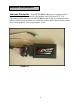
Module Installation Harness Connector – Your ECAT1000 module may be equipped with a harness that can be disconnected at the module itself (See figure 1A). It is important to make sure that your ECAT1000 module is always connected to the harness when the wiring harness is connected to the vehicle, otherwise the vehicle may not run properly, or may trip engine “codes.
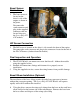
Boost Sensor Connection 1. Boost Sensor The boost sensor is located on the driver’s side of the engine as shown in the photo. Disconnect the stock connector and plug in the supplied connectors that are located closest to the Power Edge EZ CAT module. IAP Sensor Connectors IAP Sensor Connection 2. The IAP sensor is located on the driver’s side towards the front of the engine. Disconnect the stock connector and plug in the connectors located at the end of the EZ CAT harness (furthest from the module).
7. Using the 7/16” wrench, unscrew the stock brass elbow out of the turbocharger housing. Using the 7/16” wrench, install the supplied brass elbow, tighten-be careful not to over-tighten. Slip the supplied hose clamp onto the stock hose, install the stock hose onto the newly installed brass elbow and tighten the hose clamp with the ¼” socket. Fueling Adjustment The Power Edge EZ CAT Module features 4 different levels of fueling. The Module is set default to level 2. 1.
Technical Support: 888-360-3343 To expedite your support call, please have part number (i.e., EAF2100A), version number, and Date of Manufacture ready prior to calling support.