
Quick Start Guide-R01

– 1 –
Quick Start Guide
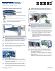
1. Unpack the Switch and Check Contents
Wedge-16X-AC
Wedge-16X-DC
Rack Mounting Kit—contains two brackets and eight
M4 x 0.7 screws
Grounding Wire (included with DC PSUs only)
Documentation—Quick Start Guide (this document)
and Safety and Regulatory Information
2. Mount the Switch
Caution:
Do not mount the switch using only the supplied
brackets. The switch requires rack L-shape brackets (or a
shelf) to be intalled in a 4-post rack before mounting.
Based on your rack plan, install L-shape brackets (or a shelf)
between the front and rear rack posts at the installation
position in the rack.
Attach the supplied brackets to each side of the switch.
Mount the switch in the rack, and then tighten the bracket
thumb-screws to secure the switch in the rack.
3. Ground the Switch
Ensure the rack is properly grounded and in compliance
with ETSI ETS 300 253. Verify that there is a good electrical
connection to the grounding point on the rack (no paint or
isolating surface treatment).
Attach a lug (not provided with AC PSUs) to an 18 AWG
minimum grounding wire (not provided with AC PSUs), and
connect it to the grounding point on the switch rear panel.
Then connect the other end of the wire to rack ground.
3
1
2
1
2
3
2
1
1
2
Caution:
The earth connection must not be removed
unless all supply connections have been disconnected.
4. Connect Power
Warning:
Before wiring the DC plug or connecting power
to the switch, ensure that power to the feed lines is turned
off at the supply circuit breaker or disconnected from the
power bus.
Install two AC or two DC power modules in the switch.
Connect an external AC or DC power source to the modules.
◆
For AC PSUs: Unwind the velcro strip before plugging in
the AC power cord, and then use the velcro strip to
secure the cord to the PSU.
◆
For DC PSUs: Connect the external power feed and
power ground/return lines to the DC plug. The -42 VDC
power feed connects to the “-” pin, and the ground/
return to the “+” pin.
5. Verify Switch Operation
Verify basic switch operation by checking the PSU LEDs.
When operating normally, the PSU OK LEDs should be on
green and the FAIL LEDs off.
If a FAIL LED is on solid amber, the PSU has an over current,
over voltage, under voltage, over temperature, or fan failure.
Replace the PSU.
If a FAIL LED is blinking amber, there is an over temperature
condition or a blocked (under speed) fan. Replace the PSU.
1
1
2
2
1
2
1
1
1
E102015-CS-R01
150200001214A
Wedge-16X-AC / Wedge-16X-DC
www.edge-core.com