GS-3008P User Manual 11-2017 / v1.
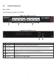
CONTENTS Chapter 1 Safety and Regulatory........................................................... 4 Chapter 2 Introduction ......................................................................... 5 2-1 2-2 2-3 2-4 Overview ...............................................................................................................................5 Package contents ..................................................................................................................5 Features ..........
5-9 5-10 5-11 5-12 Rate Limiting .......................................................................................................................28 Loop Detect/Prevent...........................................................................................................29 IGMP Snooping ....................................................................................................................30 PoE .........................................................................................
Chapter 1 Safety and Regulatory Audience This guide is for the networking professionals in managing the standalone GS-3008P switch series. It is recommended that only professionals with experience in Edimax networking devices and who are familiar with the Ethernet and local area networking terminology to service the equipment.
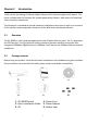
Chapter 2 Introduction Thank you for purchasing an Edimax Gigabit Ethernet PoE+ Web managed switch device. The Series includes both PoE and non-PoE models powered by Edimax’s Web Smart PoE and Web Smart interface, respectively. This document is intended to provide hardware installation instructions as well as an overview of the interface and management functions of the Web Smart web-based software. 2-1 Overview The GS-3008P is a PoE+ web managed switch with 8 Gigabit Ethernet ports.
2-3 Features IEEE 802.3af/at PoE compliant. Five Gigabit Ethernet ports. Up to 30W per port (total power budget: 72W) for powering PoE-enabled devices. Auto-detection of powered devices (PD) and power consumption levels. Auto fault-detection on over/under current & voltage. Access Control List (ACL) support. Switch capacity: 16Gbps & Forwarding rate: 11.9Mpps. IEEE 802.1Q-based VLAN for network segmentation to improve performance and security. IEEE 802.
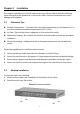
2-4 Product Components 2-4-1 Ports The following view applies to GS-3008P. Figure 1 GS-3008P Front View 1 2 3 Figure 2 GS-3008P Rear View 4 No. Name 1 2 Reset button 4 Ethernet (LAN) PoE ports (1-4) Ethernet (LAN) ports (5-8) • Power • 5 DC power in 3 5 Description Press 6 seconds to restore factory default parameters. PoE ports, compatible with IEEE 802.3af, with 60W dedicated internal power. Designed to connect to network devices with a bandwidth of 10Mbps, 100Mbps or 1000Mbps.
2-4-2 LED Indicators The following view applies to GS-3008P.
Chapter 3 Installation This chapter describes how to install and connect your Edimax Switch. Read the following topics and perform the procedures in the correct order. Incorrect installation may cause damage to the product. 3-1 Placement Tips Ambient Temperature – To prevent the switch from overheating, do not operate it in an area that exceeds an ambient temperature of 122°F (50°C). Air Flow – Be sure that there is adequate air flow around the switch.
Chapter 4 Getting Started This section provides an introduction to the web-based configuration utility, and covers the following topics: Powering on the device Connecting to the network Power over Ethernet (PoE) considerations Starting the web-based configuration utility 4-1 Power 4-1-1 Connecting to Power The switch is powered by the DC 100-240 V 50/60Hz internal high-performance power supply.
4-1-2 Connecting to the Network To connect the switch to the network: 1. Connect an Ethernet cable to the Ethernet port of a computer 2. Connect the other end of the Ethernet cable to one of the numbered Ethernet ports of the switch. The LED of the port will light up to indicate active connection. 3. Repeat Step 1 and Step 2 for the devices to be connected to the switch. We strongly recommend using CAT-5E or better cable to connect network devices.
4-1-3 Power over Ethernet (PoE) Considerations For PoE switch models, consider the following information: Devices considered a Power Sourcing Equipment (PSE), can support up to 30 Watts per PoE port on ports 1 to 4 and 30 Watts per PoE port on other ports to a Powered Device (PD). Model Power Dedicated to PoE PoE Ports PoE Standard Supported 3008P 60W 1 to 4 IEEE802.
4-1-4 Starting the Web-based Configuration Utility This section describes how to navigate the web-based switch configuration utility. 4-1-5 Browser Restrictions If you are using older versions of Internet Explorer, you cannot directly use an IPv6 address to access the device. You can, however, use the DNS (Domain Name System) server to create a domain name that contains the IPv6 address, and then use that domain name in the address bar in place of the IPv6 address.
4-2 Logging In The default username is admin and the default password is 1234. The first time that you log in with the default username and password, you are required to enter a new password. When the login attempt is successful, the System Information Status window displays: Figure 8 System Information Status If you entered incorrect username or password, an error message appears and the Login page remains displayed on the window.
Chapter 5 Web-based Switch Configuration The PoE Smart-Lite switch software provides rich Layer 2 functionality for switches in your networks. This chapter describes how to use the web-based management interface (Web UI) to configure the switch’s features. For the purposes of this manual, the user interface is separated into two sections, as shown in the following figure: Figure 9 User Interface 1 No. Name 1 2 2 Description Configuration Menu Navigate to locate specific switch functions.
5-1 System Information Use this page to view status information such as Device Name, MAC address, IP Address and loop status. To view the System Information menu, navigate to System Information. Figure 10 System Information Item Model Name Device Name Firmware Version Build Date Description Switch model name. System name of the switch, configurable according to user preference. Current firmware version of the device. Device production date.
5-2 Management Use this page to reset the switch to original factory default settings, reboot the switch, backup and restore switch settings, and upgrade firmware. To view the Management menu, navigate to Management. Figure 11 Management Item Description DHCP Enable Obtain an IP address automatically. Disable Use a static IP address Management Reset Restore switch to original factory default settings. Reboot Reboot switch.
5-3 Port Use this page to view traffic information such as Speed, Connection,TX, RX, on each port. The tracking data on each port can also be reset. To view the Port menu, navigate to Port. Figure 12 Port Item Port Speed Connection TX RX Clear Counters Description Designated port number. To control the direction and speed of data flow. • Auto • 10M Half 100M Half • 10M Full 100M Full Displays whether or not port is in use, and link speed if it is in use.
5-4 VLAN Use this section to create and modify VLANs. 5-4-1 IEEE 802.1Q VLAN To view the IEEE 802.1Q VLAN menu, navigate to VLAN. Figure 13 VLAN Item Description Apply Port PVID Create New VLAN VLAN ID Non-Member Tag Egress Member Untag Egress Member Modify Delete Click Apply to save the values and update the screen. Designated port number. Enter a VLAN ID for each port. Click Create New VLAN to enter new VLAN settings. Virtual LAN ID. Port is not a member of a VLAN.
5-5 Link Aggregation Use this option to aggregate multiple Ethernet ports together to form a logical port. This feature supports static allocation and Link Aggregation Control Protocol . To view the Link Aggregation menu, navigate to Link Aggregation. Figure 14 Link Aggregation Item Description Apply LACP Global State Click Apply to save the values and update the screen. Enable/disable LCAP.
5-6 Port Mirror Port mirroring selects the network traffic for analysis by a network analyzer. This is done for specific ports of the switch. As such, many switch ports are configured as source ports and one switch port is configured as a destination port. To view the Mirror menu, navigate to Mirror. Figure 15 Port Mirroring Item Port Mirroring Mode Monitor Port Mirrored Port Apply Description • • • • Disable port mirroring/Select the port mirroring direction.
5-7 QoS Use this section to configure Quality of Service (QoS) settings. 5-7-1 Disable QoS To view the Disable QoS menu, navigate to QoS > Disable QoS. Figure 16 QoS > Disable QoS Item Description Disable QoS Port-Based QoS IEEE 802.1p QoS Enable/disable QoS. Click to select port-based QoS settings. Click to enter IEEE 802.1Q QoS settings.
5-7-2 Port-Based QoS To view the Port-Based QoS menu, navigate to QoS > Port-Based QoS Figure 17 QoS > Port-Based QoS Item Description Disable QoS Port-Based QoS IEEE 802.1p QoS Port Enable/disable QoS. Click to select port-based QoS settings. Port-Based QoS Designated port number. According to the resource allocation strategy of the system, choose the allocated algorithm as Strict Priority or WFQ. Queue priority value. More packets are sent from a queue with a higher weight value.
To view the Port-Based QoS menu, navigate to QoS > Port-Based QoS Figure 18 QoS > Port-Based QoS Item Description Disable QoS Port-Based QoS IEEE 802.1p QoS Port Enable/disable QoS. Click to select port-based QoS settings. Port-Based QoS. Designated port number. According to the resource allocation strategy of the system to choose the allocated algorithm as Strict Priority or WFQ. Queues used to store traffic until it can be processed or serialized.
5-7-3 IEEE 802.1p QoS To view the IEEE 802.1p QoS menu, navigate to QoS > IEEE 802.1p QoS. Figure 19 QoS > IEEE 802.1p QoS Item Description Disable QoS Port-Based QoS IEEE 802.1p QoS Port Enable/disable QoS. Click to select port-based QoS settings. Click to enter IEEE 802.1Q QoS settings. Designated port number. According to the resource allocation strategy of the system to choose the allocated algorithm as Strict Priority or WFQ. Queue priority value.
To view the IEEE 802.1p QoS menu, navigate to QoS > IEEE 802.1p QoS Figure 20 QoS > IEEE 802.1p QoS Item Description Disable QoS Port-Based QoS IEEE 802.1p QoS Port Enable/disable QoS. Click to select port-based QoS settings. Click to enter IEEE 802.1Q QoS settings. Designated port number. According to the resource allocation strategy of the system to choose the allocated algorithm as Strict Priority or WFQ. Queues used to store traffic until it can be processed or serialized.
5-8 Storm Control This page allows you to set ingress port monitoring. To view the Storm Control menu, navigate to Storm Control. Figure 21 Storm Control Item Broadcast Multicast Unicast Apply Description Set Broadcast storm control limit: • Unlimited • 512Kbp/s to 512Mbp/s Set Multicast storm control limit: • Unlimited • 512Kbp/s to 512Mbp/s Set Unicast storm control limit: • Unlimited • 512Kbp/s to 512Mbp/s Click Apply to save the values and update the screen.
5-9 Rate Limiting This page allows you to display and configure ingress and egress port monitoring settings. Use this page to configure ingress and egress rate limit settings. To view the Rate Limiting menu, navigate to Rate Limit. Figure 22 Rate Limit Item Description Apply Port Click Apply to save the values and update the screen. Designated port number.
5-10 Loop Detect/Prevent Use this section to enable/disable and configure network routing loop detection. Select settings from the drop down menu. To view the Loop Detection/Prevention menu, navigate to Loop Detection/Prevention. Figure 23 Network > Loop Detection Item Description Off Loop Detection Loop Prevention Apply Disable loop detection and prevention. Enable loop detection. Enable loop prevention Click Apply to save the values and update the screen.
5-11 IGMP Snooping Use this section to create an IGMP Snooping Profile. Internet Group Management Protocol (IGMP) Snooping is a feature that allows a switch to forward multicast traffic intelligently on the switch. Multicast IP traffic is traffic that is destined to a host group. Host groups are identified by class D IP addresses, which ranges from 224.0.0.0 to 239.255.255.255. Based on the IGMP query and report messages, the switch forwards traffic only to the ports that request the multicast traffic.
5-12 PoE Use this section to configure PoE settings for the switch and its ports. PoE Global Settings and PoE Status To view the PoE Global Settings and PoE Status menu, navigate to PoE. Figure 25 PoE Menu Item PoE Global Settings PSE Total Power PoE MAX LED Power Item PSE vport voltage PoE Status Port Power Status Real Power (W) Description Enter values for PSE1 and PSE2, for a total PSE power which must not exceed 60W. Displays the maximum power supplied to LEDs.
5-12-1 PoE Port Configuration To view the PoE Port Configuration menu, navigate to PoE > PoE Status and click on an individual port number. Figure 26 PoE > PoE Status > Port Number Item Port Power Supply Apply Description Designated port number. Use the drop down menu to select port power supply options: • Turn on • Turn off Click Apply to save the values and update the screen.
5-13 Password Use these settings to change an account password. To view the Password menu, navigate to Password. Figure 27 Password Item Description Confirm Old Password New Password Confirm New Password Click Confirm to save the values and update the screen. Enter current password. Enter new password. Enter new password again to confirm. 5-14 Logout Click Logout to leave the switch management menu and close the web management session.
COPYRIGHT Copyright Edimax Technology Co., Ltd. all rights reserved. No part of this publication may be reproduced, transmitted, transcribed, stored in a retrieval system, or translated into any language or computer language, in any form or by any means, electronic, mechanical, magnetic, optical, chemical, manual or otherwise, without the prior written permission from Edimax Technology Co., Ltd. Edimax Technology Co., Ltd.
Federal Communication Commission Interference Statement This equipment has been tested and found to comply with the limits for a Class B digital device, pursuant to Part 15 of FCC Rules. These limits are designed to provide reasonable protection against harmful interference in a residential installation. This equipment generates, uses, and can radiate radio frequency energy and, if not installed and used in accordance with the instructions, may cause harmful interference to radio communications.
This equipment is designed with the utmost care for the safety of those who install and use it. However, special attention must be paid to the dangers of electric shock and static electricity when working with electrical equipment. All guidelines of this and of the computer manufacture must therefore be allowed at all times to ensure the safe use of the equipment.
EU Declaration of Conformity English: This equipment is in compliance with the essential requirements and other relevant provisions of Directive 1995/5/EC, 2009/125/EC, 2006/95/EC, 2011/65/EC. Français: Cet équipement est conforme aux exigences essentielles et autres dispositions de la directive 1995/5/CE, 2009/125/CE, 2006/95/CE, 2011/65/CE. Čeština: Toto zařízení je v souladu se základními požadavky a ostatními příslušnými ustanoveními směrnic 1995/5/ES, 2009/125/ES, 2006/95/ES, 2011/65/ES.
Declaration of Conformity We, Edimax Technology Co., Ltd., declare under our sole responsibility, that the equipment described below complies with the requirements of the European R&TTE directives. Equipment: GS-3008P PoE+ Web Smart Switch Model No.
Notice According to GNU General Public License Version 2 This product includes software that is subject to the GNU General Public License version 2. The program is free software and distributed without any warranty of the author. We offer, valid for at least three years, to give you, for a charge no more than the costs of physically performing source distribution, a complete machine-readable copy of the corresponding source code.
We protect your rights with two steps: (1) copyright the software, and (2) offer you this license which gives you legal permission to copy, distribute and/or modify the software. Also, for each author’s protection and ours, we want to make certain that everyone understands that there is no warranty for this free software.
b) You must cause any work that you distribute or publish, that in whole or in part contains or is derived from the Program or any part thereof, to be licensed as a whole at no charge to all third parties under the terms of this License.
If distribution of executable or object code is made by offering access to copy from a designated place, then offering equivalent access to copy the source code from the same place counts as distribution of the source code, even though third parties are not compelled to copy the source along with the object code. 4. You may not copy, modify, sublicense, or distribute the Program except as expressly provided under this License.
limitation excluding those countries, so that distribution is permitted only in or among countries not thus excluded. In such case, this License incorporates the limitation as if written in the body of this License. 9. The Free Software Foundation may publish revised and/or new versions of the General Public License from time to time. Such new versions will be similar in spirit to the present version, but may differ in detail to address new problems or concerns.