AC1300 DBDC Ceiling‐mount AP CAP1300, Office 1‐2‐3, Office +1, Office +3, Office WiFi System, Office WiFi System +1. User Manual 04‐2015 / v1.
CONTENTS OVERVIEW: IMPORTANT .............................................................................. 1 I. Product Information....................................................................................................................................... 2 I‐1. I‐2. I‐3. I‐4. I‐5. I‐6. Package Contents .................................................................................................................. 2 System Requirements .........................................................
IV‐3‐1‐3‐2. WEP ........................................................................................................................... 40 IV‐3‐1‐3‐3. IEEE802.1x/EAP ......................................................................................................... 40 IV‐3‐1‐3‐4. WPA‐PSK ................................................................................................................... 40 IV‐3‐1‐3‐5. WPA‐EAP ..........................................................................
IV‐2‐1. IV‐2‐2. IV‐2‐3. IV‐2‐4. IV‐2‐5. IV‐3. IV‐4. IV‐4‐1. IV‐4‐1‐1. IV‐4‐1‐2. IV‐4‐2. IV‐4‐2‐1. IV‐4‐2‐2. System Information ............................................................................................................ 91 Devices Information ............................................................................................................ 91 Managed AP ........................................................................................................................
IV‐6‐2‐3‐3. IEEE802.1x/EAP ....................................................................................................... 150 IV‐6‐2‐3‐4. WPA‐PSK ................................................................................................................. 150 IV‐6‐2‐3‐5. WPA‐EAP ................................................................................................................. 150 IV‐6‐2‐3‐6. Additional Authentication................................................................
V‐1. V‐1‐1. V‐1‐2. V‐1‐3. V‐1‐4. V‐1‐5. Configuring your IP address ............................................................................................ 190 Windows XP .................................................................................................................... 191 Windows Vista ................................................................................................................ 193 Windows 7 .........................................................................
OVERVIEW Your access point can function in three different modes. The default mode for your access point is AP mode. AP mode is a regular access point for use in your wireless network. AP Controller mode acts as the designated master of an AP array (group of linked access points). Managed AP mode acts as a “slave” AP within the AP array (controlled by the AP Controller “master”). In AP Controller mode the user interface will switch to Edimax Pro NMS.
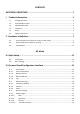
I. Product Information I‐1. Package Contents 1 2 4 5 3 6 7 8 1. CAP1300 Access Point 4. CD 2. Ceiling Mount Bracket 5. Quick Installation Guide 3. T‐Rail Mounting Kit & 6. Ethernet Cable Screws 7. Power Adapter 8. Ceiling Mount Screw Template I‐2.
I‐3.
I‐4. LED Status LED Color Blue LED Status Description On The access point is on. Long Flashing Upgrading firmware. Short Flashing Resetting to factory defaults. Amber Off On Flashing Off Starting up. Error. The access point is off.
I‐5. Reset If you experience problems with your access point, you can reset the device back to its factory settings. This resets all settings back to default. 1. Press and hold the reset button on the access point for at least 10 seconds. You may need to use a pin or similar sharp object to push the reset button. 2. Wait for the access point to restart. The access point is ready for setup when the LED is blue.
I‐6. Safety Information In order to ensure the safe operation of the device and its users, please read and act in accordance with the following safety instructions. 1. The access point is designed for indoor use only; do not place the access point outdoors. 2. Do not place the access point in or near hot/humid places, such as a kitchen or bathroom. 3. Do not pull any connected cable with force; carefully disconnect it from the access point. 4. Handle the access point with care.
II. Hardware Installation When using the access point in AP mode it is recommended to configure some basic settings as shown in III. Quick Setup before hardware installation. II‐1. Connecting the access point to a router or PoE switch 1. If you need to, remove the cap from the underside of the access point. This creates extra space for your cables to pass through. 2. Connect a router or PoE switch to the access point’s LAN port using an Ethernet cable. 3.
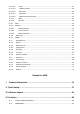
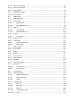
II‐2. Mounting the access point to a ceiling To mount the access point to a ceiling, please follow the instructions below and refer to diagram A & B. For Wooden Ceilings (refer to diagram A): 1. Place the ceiling mount bracket to a ceiling in your desired location and insert screw iii through hole i (x 2)and tighten to fix the bracket in place. 2. When the ceiling bracket is in place, inset screw iv into hole v (x 2) on the access point. 3.
A ii i iii 9
B 10
II‐3. T‐Rail Mount To mount the access point to a T‐Rail, please follow the instructions below and refer to diagram C, D & E. 1. Select the correct size T‐Rail bracket from the two sizes which are included in the package contents. 2. Attach the T‐Rail bracket i to hole ii using screw iii (x 2) as shown in C.
12
AP Mode III. Quick Setup Your access point can be up and running in just a few minutes. This quick installation guide will help to set up your access point in its default AP mode and configure its basic settings. For use a Managed AP within an AP array no settings are necessary. Configurations can be made from your Controller AP (refer to Edimax Pro NMS). III‐1. Initial Setup 1. Connect the access point to a computer via Ethernet cable. 2.
AP Mode 6. You will be prompted for a username and password. Enter the default username “admin” and the default password “1234”. 7. You will arrive the “System Information” screen shown below. 8. Next, please follow the instructions below in II‐2. Basic Settings to configure the access point’s basic settings.
AP Mode For more advanced configurations, please refer to IV. Browser Based Configuration Interface. III‐2. Basic Settings The instructions below will help you to configure the following basic settings of the access point: ‐ ‐ ‐ ‐ LAN IP Address 2.4GHz SSID & Security Administrator Name & Password Time & Date It is recommended you configure these settings before using the access point. 1.
AP Mode To utilize multiple 2.4GHz SSIDs, open the drop down menu labelled “Enable SSID number” and select how many SSIDs you require. Then enter a new SSID in the corresponding numbered fields below, before clicking “Apply”. 4. To configure the security of your access point’s 2.4GHz wireless network(s), go to “Wireless Setting” > “2.4GHz 11bgn” > “Security”. Select an “Authentication Method” and enter a “Pre‐shared Key” or “Encryption Key” depending on your choice, then click “Apply”.
AP Mode 5. To change the administrator name and password for the browser based configuration interface, go to “Management” > “Admin”. 6. Complete the “Administrator Name” and “Administrator Password” fields and click “Apply”. 7. To set the correct time for your access point, go to “Management” > “Date and Time”. 8. Set the correct time and time zone for your access point using the drop down menus.
AP Mode You can use the “Acquire Current Time from your PC” button if you wish to set the access point to the same time as your PC. 9. The basic settings of your access point are now configured. Please refer to II. Hardware Installation for guidance on connecting your access point to a router or PoE switch.
AP Mode IV. Browser Based Configuration Interface In Managed AP mode some functions of the browser based configuration interface are disabled. Please use Edimax Pro NMS on your Controller AP to configure your Managed AP(s). The browser‐based configuration interface enables you to configure the access point’s advanced features. The CAP1300 features a range of advanced functions such as MAC filtering, MAC RADIUS authentication, VLAN configurations, up to 32 SSIDs and many more.
AP Mode 5. Use the menu across the top and down the left side to navigate. 6. Click “Apply” to save changes and reload the access point, or “Cancel” to cancel changes. Please wait a few seconds for the access point to reload after you “Apply” changes, as shown below. 7. Please refer to the following chapters for full descriptions of the browser based configuration interface features.
AP Mode IV‐1. Information Screenshots displayed are examples. The information shown on your screen will vary depending on your configuration. IV‐1‐1. System Information The “System Information” page displays basic system information about the access point.
AP Mode System Model Product Name Uptime Boot From Version MAC Address Management VLAN ID IP Address Default Gateway DNS DHCP Server Displays the model number of the access point. Displays the product name for reference, which consists of “AP” plus the MAC address. Displays the total time since the device was turned on. Displays information for the booted hardware, booted from either USB or internal memory. Displays the firmware version. Displays the access point’s MAC address.
AP Mode Wired LAN Port Settings Wired LAN Port Specifies which LAN port (1 or 2). Status Displays the status of the specified LAN port (connected or disconnected). VLAN Mode/ID Displays the VLAN mode (tagged or untagged) and VLAN ID for the specified LAN port. See IV‐2‐3. VLAN Wireless 2.4GHz Status MAC Address Channel Transmit Power Displays the status of the 2.4GHz wireless (enabled or disabled). Displays the access point’s MAC address.
AP Mode IV‐1‐2. Wireless Clients The “Wireless Clients” page displays information about all wireless clients connected to the access point on the 2.4GHz frequency. Refresh time Auto Refresh Time Manual Refresh Select a time interval for the client table list to automatically refresh. Click refresh to manually refresh the client table. 2.4GHz WLAN Client Table SSID Displays the SSID which the client is connected to. MAC Address Displays the MAC address of the client.
AP Mode IV‐1‐3. Wireless Monitor Wireless Monitor is a tool built into the access point to scan and monitor the surrounding wireless environment. Select a frequency and click “Scan” to display a list of all SSIDs within range along with relevant details for each SSID. Wireless Monitor Site Survey Channel Survey Result Site Survey Results Ch SSID MAC Address Security Signal (%) Type Vendor Click “Scan” to begin the survey. After a scan is complete, click “Export” to save the results to local storage.
AP Mode IV‐1‐4. Log The system log displays system operation information such as up time and connection processes. This information is useful for network administrators. When the log is full, old entries are overwritten. Save Clear Refresh Click to save the log as a file on your local computer. Clear all log entries. Refresh the current log.
AP Mode The following information/events are recorded by the log: USB Mount & unmount Wireless Client Connected & disconnected Key exchange success & fail Authentication Authentication fail or successful. Association Success or fail WPS M1 ‐ M8 messages WPS success Change Settings System Boot Displays current model name NTP Client Wired Link LAN Port link status and speed status Proxy ARP Proxy ARP module start & stop Bridge Bridge start & stop. SNMP SNMP server start & stop.
AP Mode IV‐2. Network Settings Screenshots displayed are examples. The information shown on your screen will vary depending on your configuration. IV‐2‐1. LAN‐Side IP Address The “LAN‐side IP address” page allows you to configure your access point on your Local Area Network (LAN). You can enable the access point to dynamically receive an IP address from your router’s DHCP server or you can specify a static IP address for your access point, as well as configure DNS servers.
AP Mode Default Gateway For DHCP users, select “From DHCP” to get default gateway from your DHCP server or “User‐Defined” to enter a gateway manually. For static IP users, the default value is blank. DHCP users can select to get DNS servers’ IP address from DHCP or manually enter a value. For static IP users, the default value is blank. Primary Address DHCP users can select “From DHCP” to get primary DNS server’s IP address from DHCP or “User‐Defined” to manually enter a value.
AP Mode IV‐2‐2. LAN Port The “LAN Port” page allows you to configure the settings for your access point’s two wired LAN (Ethernet) ports. Wired LAN Port Enable Speed & Duplex Flow Control 802.3az Identifies LAN port 1 or 2. Enable/disable specified LAN port. Select a speed & duplex type for specified LAN port, or use the “Auto” value. LAN ports can operate up to 1000Mbps and full‐duplex enables simultaneous data packets transfer/receive. Enable/disable flow control.
AP Mode IV‐2‐3. VLAN The “VLAN” (Virtual Local Area Network) enables you to configure VLAN settings. A VLAN is a local area network which maps workstations virtually instead of physically and allows you to group together or isolate users from each other. VLAN IDs 1 – 4095 are supported. VLAN IDs in the range 1 – 4095 are supported. VLAN Interface Wired LAN Port/Wireless VLAN Mode VLAN ID Identifies LAN port 1 or 2 and wireless SSIDs. Select “Tagged Port” or “Untagged Port” for specified LAN interface.
AP Mode IV‐3. Wireless Settings Screenshots displayed are examples. The information shown on your screen will vary depending on your configuration. IV‐3‐1. 2.4GHz 11bgn The “2.4GHz 11bgn” menu allows you to view and configure information for your access point’s 2.4GHz wireless network across five categories: Basic, Advanced, Security, WDS & Schedule.
AP Mode IV‐3‐1‐1. Basic The “Basic” screen displays basic settings for your access point’s 2.4GHz Wi‐Fi network (s).
AP Mode Wireless Enable or disable the access point’s 2.4GHz wireless radio. When disabled, no 2.4GHz SSIDs will be active. Band Select the wireless standard used for the access point. Combinations of 802.11b, 802.11g & 802.11n can be selected. Enable SSID Number Select how many SSIDs to enable for the 2.4GHz frequency from the drop down menu. A maximum of 16 can be enabled. SSID# Enter the SSID name for the specified SSID (up to 16).
AP Mode When auto channel is disabled, select a wireless channel manually: Channel Channel Bandwidth BSS BasicRate Set Select a wireless channel from 1 – 11. Set the channel bandwidth: 20MHz (lower performance but less interference), 40MHz (higher performance but potentially higher interference) or Auto (automatically select based on interference level). Set a Basic Service Set (BSS) rate: this is a series of rates to control communication frames for wireless clients.
AP Mode IV‐3‐1‐2. Advanced These settings are for experienced users only. Please do not change any of the values on this page unless you are already familiar with these functions. Changing these settings can adversely affect the performance of your access point. Contention Slot Preamble Type Guard Interval Select “Short” or “Long” – this value is used for contention windows in WMM (see IV‐3‐6. WMM). Set the wireless radio preamble type. The preamble type in 802.
AP Mode 802.11g Protection Enable/disable 802.11g protection, which increases reliability but reduces bandwidth (clients will send Request to Send (RTS) to access point, and access point will broadcast Clear to Send (CTS), before a packet is sent from client.) 802.11n Protection Enable/disable 802.
AP Mode IV‐3‐1‐3. Security The access point provides various security options (wireless data encryption). When data is encrypted, information transmitted wirelessly cannot be read by anyone who does not know the correct encryption key. It’s essential to configure wireless security in order to prevent unauthorised access to your network. Select hard‐to‐guess passwords which include combinations of numbers, letters and symbols, and change your password regularly.
AP Mode SSID Selection Broadcast SSID Wireless Client Isolation Load Balancing Authentication Method Additional Authentication Select which SSID to configure security settings for. Enable or disable SSID broadcast. When enabled, the SSID will be visible to clients as an available Wi‐Fi network. When disabled, the SSID will not be visible as an available Wi‐Fi network to clients – clients must manually enter the SSID in order to connect.
AP Mode IV‐3‐1‐3‐2. WEP WEP (Wired Equivalent Privacy) is a basic encryption type. For a higher level of security consider using WPA encryption. Key Length Key Type Default Key Encryption Key 1 – 4 Select 64‐bit or 128‐bit. 128‐bit is more secure than 64‐bit and is recommended. Choose from “ASCII” (any alphanumerical character 0‐9, a‐z and A‐Z) or “Hex” (any characters from 0‐9, a‐f and A‐F). Select which encryption key (1 – 4 below) is the default key.
AP Mode Pre‐Shared Key characters from 0‐9, a‐f and A‐F). Please enter a security key/password according to the format you selected above. IV‐3‐1‐3‐5. WPA‐EAP WPA Type Encryption Type Key Renewal Interval Select from WPA/WPA2 Mixed Mode‐EAP, WPA2‐EAP or WPA‐EAP. Select “TKIP/AES Mixed Mode” or “AES” encryption type. Specify a frequency for key renewal in minutes. WPA‐EAP must be disabled to use MAC‐RADIUS authentication. IV‐3‐1‐3‐6.
AP Mode WPS must be disabled to use MAC‐RADIUS authentication. See IV‐3‐3. for WPS settings. MAC RADIUS Password Select whether to use MAC address or password authentication via RADIUS server. If you select “Use the following password”, enter the password in the field below. The password should match the “Shared Secret” used in IV‐3‐4. RADIUS.
AP Mode IV‐3‐1‐4. WDS Wireless Distribution System (WDS) can bridge/repeat access points together in an extended network. WDS settings can be configured as shown below. When using WDS, configure the IP address of each access point to be in the same subnet and ensure there is only one active DHCP server among connected access points, preferably on the WAN side. WDS must be configured on each access point, using correct MAC addresses.
AP Mode 2.4GHz WDS Functionality Select “WDS with AP” to use WDS with access point or “WDS Dedicated Mode” to use WDS and also block communication with regular wireless clients. When WDS is used, each access point should be configured with corresponding MAC addresses, wireless channel and wireless encryption method. Local MAC Address Displays the MAC address of your access point.
AP Mode IV‐3‐1‐5. Schedule The schedule feature allows you to automate the wireless network for specified times. Check/uncheck the box “Enable Wireless Schedule” to enable/disable the wireless scheduling function. The access point’s time and date settings must be set in order to use this function. Wireless scheduling can save energy and increase the security of your network. 1. Use the “Enable” checkboxes to select schedule(s). 2.
AP Mode IV‐3‐2. WPS Wi‐Fi Protected Setup is a simple way to establish connections between WPS compatible devices. WPS can be activated on compatible devices by pushing a WPS button on the device or from within the device’s firmware/configuration interface (known as PBC or “Push Button Configuration”). When WPS is activated in the correct manner and at the correct time for two compatible devices, they will automatically connect.
AP Mode WPS WPS Product PIN Push‐Button WPS WPS by PIN WPS Security WPS Status Wireless 2.4GHz SSID Security Encryption Check/uncheck this box to enable/disable WPS functionality. WPS must be disabled when using MAC‐RADIUS authentication (see IV‐3‐1‐3‐6 & IV‐3‐4). Displays the WPS PIN code of the device, used for PIN code WPS. You will be required to enter this PIN code into another WPS device for PIN code WPS. Click “Generate PIN” to generate a new WPS PIN code.
AP Mode IV‐3‐3. RADIUS The RADIUS menu allows you to configure the access point’s external RADIUS server settings. A RADIUS server provides user‐based authentication to improve security and offer wireless client control – users can be authenticated before gaining access to a network. The access point can utilize both a primary and secondary (backup) external RADIUS server.
AP Mode Authentication Port Shared Secret Session Timeout Accounting Accounting Port Set the UDP port used in the authentication protocol of the RADIUS server. Value must be between 1 – 65535. Enter a shared secret/password between 1 – 99 characters in length. This should match the “MAC‐RADIUS” password used in IV‐3‐1‐3‐6 or IV‐3‐2‐3. Set a duration of session timeout in seconds between 0 – 86400. Enable or disable RADIUS accounting.
AP Mode IV‐3‐3‐1. RADIUS Settings Configure the RADIUS server settings for 2.4GHz. Each frequency can use an internal or external RADIUS server. RADIUS Type RADIUS Server Authentication Port Select “Internal” to use the access point’s built‐in RADIUS server or “external” to use an external RADIUS server. Enter the RADIUS server host IP address. Set the UDP port used in the authentication protocol of the RADIUS server. Value must be between 1 – 65535.
AP Mode Shared Secret Session Timeout Accounting Accounting Port Enter a shared secret/password between 1 – 99 characters in length. This should match the “MAC‐RADIUS” password used in IV‐3‐1‐3‐6 or IV‐3‐2‐3. Set a duration of session timeout in seconds between 0 – 86400. Enable or disable RADIUS accounting. When accounting is enabled (above), set the UDP port used in the accounting protocol of the RADIUS server. Value must be between 1 – 65535. IV‐3‐3‐2.
AP Mode Internal Server Check/uncheck to enable/disable the access point’s internal RADIUS server. EAP Internal Select EAP internal authentication type from Authentication the drop down menu. EAP Certificate File Displays the EAP certificate file format: Format PCK#12(*.pfx/*.p12) EAP Certificate File Click “Upload” to open a new window and select the location of an EAP certificate file to use. If no certificate file is uploaded, the internal RADIUS server will use a self‐made certificate.
AP Mode IV‐3‐3‐3. RADIUS Accounts The internal RADIUS server can authenticate up to 256 user accounts. The “RADIUS Accounts” page allows you to configure and manage users.
AP Mode User Name Add Reset Select User Name Password Customize Delete Selected Delete All Enter the user names here, separated by commas. Click “Add” to add the user to the user registration list. Clear text from the user name box. Check the box to select a user. Displays the user name. Displays if specified user name has a password (configured) or not (not configured). Click “Edit” to open a new field to set/edit a password for the specified user name (below).
AP Mode IV‐3‐4. MAC Filter Mac filtering is a security feature that can help to prevent unauthorized users from connecting to your access point. This function allows you to define a list of network devices permitted to connect to the access point. Devices are each identified by their unique MAC address. If a device which is not on the list of permitted MAC addresses attempts to connect to the access point, it will be denied.
AP Mode Add Reset commas, e.g. ‘aa‐bb‐cc‐dd‐ee‐ff,aa‐bb‐cc‐dd‐ee‐gg’ Click “Add” to add the MAC address to the MAC address filtering table. Clear all fields. MAC address entries will be listed in the “MAC Address Filtering Table”. Select an entry using the “Select” checkbox. Select MAC Address Delete Selected Delete All Export Delete selected or all entries from the table. The MAC address is listed here. Delete the selected MAC address from the list.
AP Mode IV‐3‐5. WMM Wi‐Fi Multimedia (WMM) is a Wi‐Fi Alliance interoperability certification based on the IEEE 802.11e standard, which provides Quality of Service (QoS) features to IEE 802.11 networks. WMM prioritizes traffic according to four categories: background, best effort, video and voice. Configuring WMM consists of adjusting parameters on queues for different categories of wireless traffic.
AP Mode CWMin CWMax AIFSN TxOP Minimum Contention Window (milliseconds): This value is input to the initial random backoff wait time algorithm for retry of a data frame transmission. The backoff wait time will be generated between 0 and this value. If the frame is not sent, the random backoff value is doubled until the value reaches the number defined by CWMax (below). The CWMin value must be lower than the CWMax value.
AP Mode IV‐4. Management Screenshots displayed are examples. The information shown on your screen will vary depending on your configuration. IV‐4‐1. Admin You can change the password used to login to the browser‐based configuration interface here. It is advised to do so for security purposes. If you change the administrator password, please make a note of the new password. In the event that you forget this password and are unable to login to the browser based configuration interface, see I‐5.
AP Mode Account to Manage This Device Administrator Set the access point’s administrator name. Name This is used to log in to the browser based configuration interface and must be between 4‐16 alphanumeric characters (case sensitive). Administrator Set the access point’s administrator password. Password This is used to log in to the browser based configuration interface and must be between 4‐32 alphanumeric characters (case sensitive).
AP Mode SNMP Version SNMP Get Community SNMP Set Community SNMP Trap SNMP Trap Community SNMP Trap Manager When SNMP is enabled, complete the SNMP fields below. Select SNMP version appropriate for your SNMP manager. Enter an SNMP Get Community name for verification with the SNMP manager for SNMP‐GET requests. Enter an SNMP Set Community name for verification with the SNMP manager for SNMP‐SET requests. Enable or disable SNMP Trap to notify SNMP manager of network errors.
AP Mode IV‐4‐2. Date and Time You can configure the time zone settings of your access point here. The date and time of the device can be configured manually or can be synchronized with a time server. Date and Time Settings Local Time Set the access point’s date and time manually using the drop down menus. Acquire Current Click “Acquire Current Time from Your PC” to Time from your PC enter the required values automatically according to your computer’s current time and date.
AP Mode Server Name Update Interval Time Zone Time Zone Enter the host name or IP address of the time server if you wish. Specify a frequency (in hours) for the access point to update/synchronize with the NTP server. Select the time zone of your country/ region. If your country/region is not listed, please select another country/region whose time zone is the same as yours.
AP Mode IV‐4‐3. Syslog Server The system log can be sent to a server or to attached USB storage. Syslog Server Settings Transfer Logs Check/uncheck the box to enable/disable the use of a syslog server, and enter a host name, domain or IP address for the server, consisting of up to 128 alphanumeric characters. Syslog E‐mail Settings E‐mail Logs Check the box to enable/disable e‐mail logs. E‐mail Subject Specify the subject line of log emails.
AP Mode IV‐4‐4. Ping Test The access point includes a built‐in ping test function. Ping is a computer network administration utility used to test whether a particular host is reachable across an IP network and to measure the round‐trip time for sent messages. Destination Address Enter the address of the host. Click execute to ping the host.
AP Mode IV‐4‐5. I’m Here The access point features a built‐in buzzer which can sound on command using the “I’m Here” page. This is useful for network administrators and engineers working in complex network environments to locate the access point. The buzzer is loud! Duration of Sound Sound Buzzer Set the duration for which the buzzer will sound when the “Sound Buzzer” button is clicked. Activate the buzzer sound for the above specified duration of time.
AP Mode IV‐4‐6. Operation Mode The access point can function in three different modes. Set the operation mode of the access point here. AP mode is a standalone access point, AP controller mode acts as the designated master of the AP array, and Managed AP mode acts as a slave AP within the AP array. Refer back to Overview and Edimax Pro NMS I. Product Information for more help.
AP Mode IV‐5. Advanced Screenshots displayed are examples. The information shown on your screen will vary depending on your configuration. IV‐5‐1. LED Settings The access point’s LEDs can be manually enabled or disabled according to your preference. Power LED Select on or off.
AP Mode IV‐5‐2. Update Firmware The “Firmware” page allows you to update the system firmware to a more recent version. Updated firmware versions often offer increased performance and security, as well as bug fixes. You can download the latest firmware from the Edimax website. Do not switch off or disconnect the access point during a firmware upgrade, as this could damage the device. Update Firmware Select “a file on your PC” to upload firmware From from your local computer.
AP Mode IV‐5‐3. Save/Restore Settings The access point’s “Save/Restore Settings” page enables you to save/backup the access point’s current settings as a file to your local computer or a USB device attached to the access point, and restore the access point to previously saved settings. Save / Restore Settings Using Device Select “Using your PC” to save the access point’s settings to your local computer.
AP Mode Restore Settings from PC Restore Settings Click the browse button to find a previously saved settings file on your computer, then click “Restore” to replace your current settings. If your settings file is encrypted with a password, check the “Open file with password” box and enter the password in the field underneath.
AP Mode IV‐5‐4. Factory Default If the access point malfunctions or is not responding, then it is recommended that you reboot the device (see IV‐5.5) or reset the device back to its factory default settings. You can reset the access point back to its default settings using this feature if the location of the access point is not convenient to access the reset button. Factory Default Click “Factory Default” to restore settings to the factory default. A pop‐up window will appear and ask you to confirm.
AP Mode IV‐5‐5. Reboot If the access point malfunctions or is not responding, then it is recommended that you reboot the device or reset the access point back to its factory default settings (see IV‐5‐4). You can reboot the access point remotely using this feature. Reboot Click “Reboot” to reboot the device. A countdown will indicate the progress of the reboot.
Edimax Pro NMS I. Product Information Edimax Pro Network Management Suite (NMS) supports the central management of a group of access points, otherwise known as an AP Array. NMS can be installed on one access point and support up to 8 Edimax Pro access points with no additional wireless controller required, reducing costs and facilitating efficient remote AP management.
Edimax Pro NMS II. Quick Setup Edimax Pro NMS is simple to setup. An overview of the system is shown below: One AP (access point) is designated as the AP Controller (master) and other connected Edimax Pro APs are automatically designated as Managed APs (slaves). Using Edimax Pro NMS you can monitor, configure and manage all Managed APs (up to 8) from the single AP Controller.
Edimax Pro NMS Follow the steps below: Ensure you have the latest firmware from the Edimax website for your Edimax Pro products. 1. Connect all APs to an Ethernet or PoE switch which is connected to a gateway/router. 2. Ensure all APs are powered on and check LEDs.
Edimax Pro NMS 3. Designate one AP as the AP Controller which will manage all other connected APs (up to 8). 4. Connect a computer to the designated AP Controller using an Ethernet cable.
Edimax Pro NMS 5. Open a web browser and enter the AP Controller’s IP address in the address field. The default IP address is 192.168.2.2 Your computer’s IP address must be in the same subnet as the AP Controller. Refer to V‐1. Configuring your IP Address for help. If you changed the AP Controller’s IP address, or if your gateway/router uses a DHCP server, ensure you enter the correct IP address. Refer to your gateway/router’s settings. 6. Enter the username & password to login.
Edimax Pro NMS 8. Click “Apply” to save the settings. 9. Edimax Pro NMS includes a wizard to quickly setup the SSID & security for Managed APs. Click “Wizard” in the top right corner to begin. 10. Follow the instructions on‐screen to complete Steps 1, 2 & 3 and click “Finish” to save the settings.
Edimax Pro NMS If any of your Managed APs are not found during Step 2 AP Discovery, reset the Managed AP to its factory default settings. 11. Your AP Controller & Managed APs should be fully functional. Use the top menu to navigate around Edimax Pro NMS. Use Dashboard, Zone Plan, NMS Monitor & NMS Settings to configure Managed APs. Use Local Network & Local Settings to configure your AP Controller.
Edimax Pro NMS III. Software Layout The top menu features 7 panels: Dashboard, Zone Plan, NMS Monitor, NMS Settings, Local Network, Local Settings & Toolbox. Dashboard The Dashboard panel displays an overview of your network and key system information, with quick links to access configuration options for Managed APs and Managed AP groups. Each panel can be refreshed, collapsed or moved according to your preference.
Edimax Pro NMS Zone Plan Zone Plan displays a customizable live map of Managed APs for a visual representation of your network coverage. Each AP icon can be moved around the map, and a background image can be uploaded for user‐defined location Zone Edit. Options can be configured using profiles using NMS Settings the menu on the right side and signal strength is displayed for each AP.
Edimax Pro NMS NMS Monitor The NMS Monitor panel provides more detailed monitoring information about the AP Array than found on the Dashboard, grouped according to categories in the menu down the left side.
Edimax Pro NMS NMS Settings NMS Settings provides extensive configuration options for the AP Array. You can manage each access point, assign access points into groups, manage WLAN, RADIUS & guest network settings as well as upgrade firmware across multiple access points. The Zone Plan can also be configured using “Zone Edit”.
Edimax Pro NMS Local Network Local Network settings are for your AP Controller. You can configure the IP address and DHCP server of the AP Controller in addition to 2.4GHz & 5Ghz Wi‐Fi and security, with WPS, RADIUS server, MAC filtering and WMM settings also available.
Edimax Pro NMS Local Settings Local Settings are for your AP Controller. You can set the operation mode and view network settings (clients and logs) specifically for the AP Controller, as well as other management settings such as date/time, admin accounts, firmware and reset.
Edimax Pro NMS Toolbox The Toolbox panel provides a network diagnostic tools: ping and traceroute.
Edimax Pro NMS IV. Features Descriptions of the functions of each main panel Dashboard, Zone Plan, NMS Monitor, NMS Settings, Local Network, Local Settings & Toolbox can be found below. When using Edimax NMS, click “Apply” to save changes: Screenshots displayed are examples. The information shown on your screen will vary depending on your configuration. IV‐1. LOGIN, LOGOUT & RESTART It is recommended that you login to the AP Controller to make configurations to Managed APs. LOGIN 1.
Edimax Pro NMS Your computer’s IP address must be in the same subnet as the AP Controller. Refer to V‐1. Configuring your IP Address for more help. If you changed the AP Controller’s IP address, or if your gateway/router uses a DHCP server, ensure you enter the correct IP address. Refer to your gateway/router’s settings. If using a DHCP server on the network, it is advised to use your DHCP server’s settings to assign the AP Controller a static IP address. 3. Enter the username & password to login.
Edimax Pro NMS IV‐2. DASHBOARD The dashboard displays an overview of your AP array: Use the blue icons above to refresh or collapse each panel in the dashboard. Click and drag to move a panel to suit your preference.
Edimax Pro NMS IV‐2‐1. System Information System Information displays information about the AP Controller: Product Name (model), Host Name, MAC Address, IP Address, Firmware Version, System Time and Uptime (time the access point has been on). IV‐2‐2. Devices Information Devices Information is a summary of the number of all devices in the local network: Access Points, Clients Connected, and Rogue (unidentified) Devices.
Edimax Pro NMS IV‐2‐3. Managed AP Managed AP displays information about each Managed AP in the local network: Index (reference number), MAC Address, Device Name, Model, IP Address, 2.4GHz & 5GHz Wireless Channel Number, No. of Clients connected to each access point, and Status (connected, connecting or disconnected). The search function can be used to locate a specific Managed AP.
Edimax Pro NMS 5. Network Connectivity Go to the “Network Connectivity” panel to perform a ping or traceroute. 6. Restart Restarts the Managed AP. IV‐2‐4. Managed AP Group Managed APs can be grouped according to your requirements. Managed AP Group displays information about each Managed AP group in the local network: Group Name, MAC Address, Device Name, Model, IP Address, 2.4GHz & 5GHz Wireless Channel Number, No. of Clients connected to each access point, and Status (connected or disconnected).
Edimax Pro NMS 2. Edit Edit various settings for the Managed AP (refer to IV‐5‐1. Access Point) 3. Blink LED The Managed AP’s LED will flash temporarily to help identify & locate access points. 4. Buzzer The Managed AP’s buzzer will sound temporarily to help identify & locate access points. 5. Network Connectivity Go to the “Network Connectivity” panel to perform a ping or traceroute. 6. Restart Restarts the Managed AP. IV‐2‐5.