AC1300 DBDC Ceiling-mount AP EW-7479CAP User’s Manual EW-7679WAUser Manual 05-2014 / v1.0 Version: 1.
CONTENTS I. Product Information .............................................................................. 2 I-1. I-2. I-3. I-4. I-5. I-6. Package Contents ..................................................................................................................2 System Requirements ............................................................................................................2 Hardware Overview .......................................................................................
IV-3-2. 5GHz 11ac 11an .................................................................................................................47 IV-3-2-1. Basic .............................................................................................................................47 IV-3-2-2. Advanced .....................................................................................................................50 IV-3-2-3. IV-3-2-4. IV-3-3. IV-3-4. IV-3-4-1. IV-3-4-2. IV-3-4-3. IV-3-5. IV-3-6. IV-4.
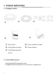
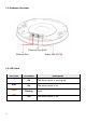
I. Product Information I-1. Package Contents 3 2 1 5 4 1. 2. 3. Access Point Ceiling Mount Bracket 4. 5. Quick Installation Guide Power Adapter T-Rail Mounting Kit & Screws I-2.
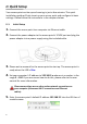
I-3. Hardware Overview Ethernet Port (PoE) Ethernet Port Power Jack (DC IN) I-4. LED Status LED Color Purple Blue Amber Off 3 LED Status Description On The access point is starting up. On The access point is on. Flashing Off Error. The access point is off.
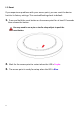
I-5. Reset If you experience problems with your access point, you can reset the device back to its factory settings. This resets all settings back to default. 1. Press and hold the reset button on the access point for at least 10 seconds then release the button. You may need to use a pin or similar sharp object to push the reset button. 2. Wait for the access point to restart when the LED is Purple. 3. The access point is ready for setup when the LED is Blue.
I-6. Safety Information In order to ensure the safe operation of the device and its users, please read and act in accordance with the following safety instructions. 1. The access point is designed for indoor use only; do not place the access point outdoors. 2. Do not place the access point in or near hot/humid places, such as a kitchen or bathroom. 3. Do not pull any connected cable with force; carefully disconnect it from the access point. 4. Handle the access point with care.
II. Quick Setup Your access point can be up and running in just a few minutes. This quick installation guide will help to set up your access point and configure its basic settings. Please follow the instructions in the chapters below: II-1. Initial Setup 1. Connect the access point to a computer via Ethernet cable. 2. Connect the power adapter to the access point’s 12VDC port and plug the power adapter into a power supply using the included cable. 3. Please wait a moment for the access point to start up.
6. You will be prompted for a username and password. Enter the default username “admin” and the default password “1234”. 7. You will arrive the “System Information” screen shown below. 8. Next, please follow the instructions below in II-2. Basic Settings to configure the access point’s basic settings.
For more advanced configurations, please refer to IV. Browser Based Configuration Interface. II-2. Basic Settings The instructions below will help you to configure the following basic settings of the access point: - LAN IP Address 2.4GHz & 5GHz SSID & Security Administrator Name & Password Time & Date It is recommended you configure these settings before using the access point. 1.
When you change your access point’s IP address, you need to use the new IP address to access the browser based configuration interface instead of the default IP 192.168.2.2. 3. To change the SSID of your access point’s 2.4GHz wireless network(s), go to “Wireless Setting” > “2.4GHz 11bgn” > “Basic”. Enter the new SSID for your 2.4GHz wireless network in the “SSID1” field and click “Apply”. To utilize multiple 2.
5. Go to “Wireless Setting” > “5GHz 11ac 11an” and repeat steps 3 & 4 for the access point’s 5GHz wireless network. 6. To change the administrator name and password for the browser based configuration interface, go to “Management” > “Admin”.
7. Complete the “Administrator Name” and “Administrator Password” fields and click “Apply”. 8. To set the correct time for your access point, go to “Management” > “Date and Time”. 9. Set the correct time and time zone for your access point using the drop down menus. The access point also supports NTP (Network Time Protocol) so alternatively you can enter the host name or IP address of a time server. Click “Apply” when you are finished.
III. Hardware Installation III-1. Connecting the access point to a router or PoE switch 1.If you need to, remove the cap from the underside of the access point. This creates extra space for your cables to pass through. 2.Connect a router or PoE switch to the access point’s LAN port using an Ethernet cable. 3. If you are using a router, then connect the power adapter to the access point’s 12V DC port and plug the power adapter into a power supply. 4.
III-2. Mounting the access point to a ceiling To mount the access point to a ceiling, please follow the instructions below and refer to diagram A & B. For Wooden Ceilings (refer to diagram A): 1. Place the ceiling mount bracket to a ceiling in your desired location and insert screw iii through hole i (x 2)and tighten to fix the bracket in place. 2. When the ceiling bracket is in place, inset screw iv into hole v (x 2) on the access point. 3.
A ii i iii 14
B 15
III-3. T-Rail Mount To mount the access point to a T-Rail, please follow the instructions below and refer to diagram C, D & E. 1. 2. Select the correct size T-Rail bracket from the two sizes which are included in the package contents. Attach the T-Rail bracket i to hole ii using screw iii (x 2) as shown in C.
D E 17
IV. Browser Based Configuration Interface The browser-based configuration interface enables you to configure the access point’s advanced features. The device features a range of advanced functions such as MAC filtering, MAC RADIUS authentication, VLAN configurations, up to 32 SSIDs and many more. To access the browser based configuration interface: 1. Connect a computer to your access point using an Ethernet cable. 2. Enter your access point’s IP address in the URL bar of a web browser.
5. 6. Use the menu across the top and down the left side to navigate. Click “Apply” to save changes and reload the access point, or “Cancel” to cancel changes. Please wait a few seconds for the access point to reload after you “Apply” changes, as shown below. 7. 19 Please refer to the following chapters for full descriptions of the browser based configuration interface features.
IV-1. Information Screenshots displayed are examples. The information shown on your screen will vary depending on your configuration. IV-1-1. System Information The “System Information” page displays basic system information about the access point.
21
System Model Product Name Uptime Boot From Version MAC Address Management VLAN ID IP Address Default Gateway DNS DHCP Server Displays the model number of the access point. Displays the product name for reference, which consists of “AP” plus the MAC address. Displays the total time since the device was turned on. Displays information for the booted hardware. Displays the firmware version. Displays the access point’s MAC address. Displays the management VLAN ID. Displays the IP address of this device.
Wireless 2.4GHz (5GHz) / SSID SSID Displays the SSID name(s) for the specified frequency. Authentication Displays the authentication method for the Method specified SSID. See IV-3. Wireless Settings Encryption Type Displays the encryption type for the specified SSID. See IV-3. Wireless Settings VLAN ID Displays the VLAN ID for the specified SSID. See IV-2-3. VLAN Additional Displays the additional authentication type for Authentication the specified SSID. See IV-3.
IV-1-2. Wireless Clients The “Wireless Clients” page displays information about all wireless clients connected to the access point on the 2.4GHz or 5GHz frequency. Refresh time Auto Refresh Time Manual Refresh Select a time interval for the client table list to automatically refresh. Click refresh to manually refresh the client table. 2.4GHz (5GHz) WLAN Client Table SSID Displays the SSID which the client is connected to. MAC Address Displays the MAC address of the client.
Connected Time Idle Time Vendor 25 Displays the total time the wireless client has been connected to the access point. Client idle time is the time for which the client has not transmitted any data packets i.e. is idle. The vendor of the client’s wireless adapter is displayed here.
IV-1-3. Wireless Monitor Wireless Monitor is a tool built into the access point to scan and monitor the surrounding wireless environment. Select a frequency and click “Scan” to display a list of all SSIDs within range along with relevant details for each SSID. Wireless Monitor Site Survey Channel Survey Result Site Survey Results Ch SSID MAC Address Security 26 Select which frequency (or both) to scan, and click “Scan” to begin.
Signal (%) Type Vendor 27 Displays the current signal strength of the SSID. Displays the 802.11 wireless networking standard(s) of the specified SSID. Displays the vendor of the wireless router/access point for the specified SSID.
IV-1-4. Log The system log displays system operation information such as up time and connection processes. This information is useful for network administrators. When the log is full, old entries are overwritten. Save Clear Refresh 28 Click to save the log as a file on your local computer. Clear all log entries. Refresh the current log.
The following information/events are recorded by the log: Wireless Client Connected & disconnected Key exchange success & fail Authentication Authentication fail or successful. Association Success or fail WPS M1 - M8 messages WPS success Change Settings System Boot Displays current model name NTP Client Wired Link LAN Port link status and speed status Proxy ARP Proxy ARP module start & stop Bridge Bridge start & stop. SNMP SNMP server start & stop. HTTP HTTP start & stop.
IV-2. Network Settings Screenshots displayed are examples. The information shown on your screen will vary depending on your configuration. IV-2-1. LAN-Side IP Address The “LAN-side IP address” page allows you to configure your access point on your Local Area Network (LAN). You can enable the access point to dynamically receive an IP address from your router’s DHCP server or you can specify a static IP address for your access point, as well as configure DNS servers.
Default Gateway For DHCP users, select “From DHCP” to get default gateway from your DHCP server or “User-Defined” to enter a gateway manually. For static IP users, the default value is blank. DHCP users can select to get DNS servers’ IP address from DHCP or manually enter a value. For static IP users, the default value is blank. Primary Address DHCP users can select “From DHCP” to get primary DNS server’s IP address from DHCP or “User-Defined” to manually enter a value.
IV-2-2. LAN Port The “LAN Port” page allows you to configure the settings for your access point’s two wired LAN (Ethernet) ports. Wired LAN Port Enable Speed & Duplex Flow Control 802.3az 32 Identifies LAN port 1. Enable/disable LAN port. Select a speed & duplex type for LAN port, or use the “Auto” value. LAN ports can operate up to 1000Mbps and full-duplex enables simultaneous data packets transfer/receive. Enable/disable flow control.
IV-2-3. VLAN The “VLAN” (Virtual Local Area Network) enables you to configure VLAN settings. A VLAN is a local area network which maps workstations virtually instead of physically and allows you to group together or isolate users from each other. VLAN IDs 1 – 4094 are supported. VLAN IDs in the range 1 – 4094 are supported. VLAN Interface Wired LAN Port/Wireless VLAN Mode VLAN ID Identifies LAN port 1 and wireless SSIDs (2.4GHz or 5GHz). Select “Tagged Port” or “Untagged Port” for LAN interface.
IV-3. Wireless Settings Screenshots displayed are examples. The information shown on your screen will vary depending on your configuration. IV-3-1. 2.4GHz 11bgn The “2.4GHz 11bgn” menu allows you to view and configure information for your access point’s 2.4GHz wireless network across four categories: Basic, Advanced, Security and WDS.
IV-3-1-1. Basic The “Basic” screen displays basic settings for your access point’s 2.4GHz Wi-Fi network (s).
Wireless Enable or disable the access point’s 2.4GHz wireless radio. When disabled, no 2.4GHz SSIDs will be active. Band Select the wireless standard used for the access point. Combinations of 802.11b, 802.11g & 802.11n can be selected. Enable SSID Number Select how many SSIDs to enable for the 2.4GHz frequency from the drop down menu. A maximum of 16 can be enabled. SSID# Enter the SSID name for the specified SSID (up to 16). The SSID can consist of any combination of up to 32 alphanumeric characters.
When auto channel is disabled, select a wireless channel manually: Channel Channel Bandwidth BSS BasicRate Set 37 Select a wireless channel from 1 – 11 (1-13). Set the channel bandwidth: 20MHz (lower performance but less interference), 40MHz (higher performance but potentially higher interference) or Auto (automatically select based on interference level). Set a Basic Service Set (BSS) rate: this is a series of rates to control communication frames for wireless clients.
IV-3-1-2. Advanced These settings are for experienced users only. Please do not change any of the values on this page unless you are already familiar with these functions. Changing these settings can adversely affect the performance of your access point. Contention Slot Preamble Type Guard Interval 38 Select “Short” or “Long” – this value is used for contention windows in WMM (see IV-3-6. WMM). Set the wireless radio preamble type. The preamble type in 802.
802.11g Protection Enable/disable 802.11g protection, which increases reliability but reduces bandwidth (clients will send Request to Send (RTS) to access point, and access point will broadcast Clear to Send (CTS), before a packet is sent from client.) 802.11n Protection Enable/disable 802.11n protection, which increases reliability but reduces bandwidth (clients will send Request to Send (RTS) to access point, and access point will broadcast Clear to Send (CTS), before a packet is sent from client.
IV-3-1-3. Security The access point provides various security options (wireless data encryption). When data is encrypted, information transmitted wirelessly cannot be read by anyone who does not know the correct encryption key. It’s essential to configure wireless security in order to prevent unauthorised access to your network. Select hard-to-guess passwords which include combinations of numbers, letters and symbols, and change your password regularly.
SSID Selection Broadcast SSID Wireless Client Isolation Load Balancing Authentication Method Additional Authentication Select which SSID to configure security settings for. Enable or disable SSID broadcast. When enabled, the SSID will be visible to clients as an available Wi-Fi network. When disabled, the SSID will not be visible as an available Wi-Fi network to clients – clients must manually enter the SSID in order to connect.
IV-3-1-3-2. WEP WEP (Wired Equivalent Privacy) is a basic encryption type. For a higher level of security consider using WPA encryption. Key Length Key Type Default Key Encryption Key 1 – 4 Select 64-bit or 128-bit. 128-bit is more secure than 64-bit and is recommended. Choose from “ASCII” (any alphanumerical character 0-9, a-z and A-Z) or “Hex” (any characters from 0-9, a-f and A-F). Select which encryption key (1 – 4 below) is the default key.
Type Pre-Shared Key alphanumeric characters) or “Hex” (up to 64 characters from 0-9, a-f and A-F). Please enter a security key/password according to the format you selected above. IV-3-1-3-5. WPA-EAP WPA Type Encryption Key Renewal Interval Select from WPA/WPA2 Mixed Mode-EAP, WPA2-EAP or WPA-EAP. Select “TKIP/AES Mixed Mode” or “AES” encryption type. Specify a frequency for key renewal in minutes. WPA-EAP must be disabled to use MAC-RADIUS authentication. IV-3-1-3-6.
MAC RADIUS Password 44 Select whether to use MAC address or password authentication via RADIUS server. If you select “Use the following password”, enter the password in the field below. The password should match the “Shared Secret” used in IV-3-4. RADIUS.
IV-3-1-4. WDS Wireless Distribution System (WDS) can bridge/repeat access points together in an extended network. WDS settings can be configured as shown below. When using WDS, configure the IP address of each access point to be in the same subnet and ensure there is only one active DHCP server among connected access points, preferably on the WAN side. WDS must be configured on each access point, using correct MAC addresses. All access points should use the same wireless channel and encryption method.
2.4GHz WDS Functionality Select “WDS with AP” to use WDS with access point or “Dedicated WDS” to use WDS and also block communication with regular wireless clients. When WDS is used, each access point should be configured with corresponding MAC addresses, wireless channel and wireless encryption method. Local MAC Address Displays the MAC address of your access point. WDS Peer Settings WDS # WDS VLAN VLAN Mode VLAN ID Enter the MAC address for up to four other WDS devices you wish to connect.
IV-3-2. 5GHz 11ac 11an The “5GHz 11ac 11an” menu allows you to view and configure information for your access point’s 5GHz wireless network across four categories: Basic, Advanced, Security and WDS. IV-3-2-1. Basic The “Basic” screen displays basic settings for your access point’s 5GHz Wi-Fi network (s). Wireless 47 Enable or disable the access point’s 5GHz wireless radio.
will be active. Band Select the wireless standard used for the access point. Combinations of 802.11a, 802.11n & 802.11ac can be selected. Enable SSID Number Select how many SSIDs to enable for the 5GHz frequency from the drop down menu. A maximum of 16 can be enabled. SSID# Enter the SSID name for the specified SSID (up to 16). The SSID can consist of any combination of up to 32 alphanumeric characters. VLAN ID Specify a VLAN ID for each SSID. Auto Channel Enable/disable auto channel selection.
BSS BasicRate Set 49 (automatically select based on interference level). Set a Basic Service Set (BSS) rate: this is a series of rates to control communication frames for wireless clients.
IV-3-2-2. Advanced These settings are for experienced users only. Please do not change any of the values on this page unless you are already familiar with these functions. Changing these settings can adversely affect the performance of your access point. Guard Interval Set the guard interval. A shorter interval can improve performance. 802.11n Protection Enable/disable 802.
Tx Power Beacon Interval Station idle timeout 51 Set the power output of the wireless radio. You may not require 100% output power. Setting a lower power output can enhance security since potentially malicious/unknown users in distant areas will not be able to access your signal. Set the beacon interval of the wireless radio. The default value is 100. Set the interval for keepalive messages from the access point to a wireless client to verify if the station is still alive/active.
IV-3-2-3. Security The access point provides various security options (wireless data encryption). When data is encrypted, information transmitted wirelessly cannot be read by anyone who does not know the correct encryption key. It’s essential to configure wireless security in order to prevent unauthorised access to your network. Select hard-to-guess passwords which include combinations of numbers, letters and symbols, and change your password regularly.
Wireless Client Isolation Load Balancing Authentication Method Additional Authentication Enable or disable wireless client isolation. Wireless client isolation prevents clients connected to the access point from communicating with each other and improves security. Typically, this function is useful for corporate environments or public hot spots and can prevent brute force attacks on clients’ usernames and passwords. Load balancing limits the number of wireless clients connected to an SSID.
IV-3-2-4. WDS Wireless Distribution System (WDS) can bridge/repeat access points together in an extended network. WDS settings can be configured as shown below. When using WDS, configure the IP address of each access point to be in the same subnet and ensure there is only one active DHCP server among connected access points, preferably on the WAN side. WDS must be configured on each access point, using correct MAC addresses. All access points should use the same wireless channel and encryption method.
5GHz WDS Mode WDS Functionality Select “WDS with AP” to use WDS with access point or “Dedicated WDS” to use WDS and also block communication with regular wireless clients. When WDS is used, each access point should be configured with corresponding MAC addresses, wireless channel and wireless encryption method. Local MAC Address Displays the MAC address of your access point.
IV-3-3. WPS Wi-Fi Protected Setup is a simple way to establish connections between WPS compatible devices. WPS can be activated on compatible devices by pushing a WPS button on the device or from within the device’s firmware/configuration interface (known as PBC or “Push Button Configuration”). When WPS is activated in the correct manner and at the correct time for two compatible devices, they will automatically connect.
WPS Check/uncheck this box to enable/disable WPS functionality. WPS must be disabled when using MAC-RADIUS authentication (see IV-3-1-3-6 & IV-3-4). Product PIN Displays the WPS PIN code of the device, used for PIN code WPS. You will be required to enter this PIN code into another WPS device for PIN code WPS. Click “Generate PIN” to generate a new WPS PIN code. Click “Start” to activate WPS on the access point for approximately 2 minutes.
IV-3-4. RADIUS The RADIUS sub menu allows you to configure the access point’s RADIUS server settings, categorized into three submenus: RADIUS settings, Internal Server and RADIUS accounts. A RADIUS server provides user-based authentication to improve security and offer wireless client control – users can be authenticated before gaining access to a network. The access point can utilize both a primary and secondary (backup) RADIUS server for each of its wireless frequencies (2.4GHz & 5GHz).
IV-3-4-1. RADIUS Settings Configure the RADIUS server settings for 2.4GHz & 5GHz. Each frequency can use an internal or external RADIUS server.
RADIUS Type Select “Internal” to use the access point’s built-in RADIUS server or “external” to use an external RADIUS server. RADIUS Server Enter the RADIUS server host IP address. Authentication Port Set the UDP port used in the authentication protocol of the RADIUS server. Value must be between 1 – 65535. Enter a shared secret/password between 1 – 99 characters in length. This should match the “MAC-RADIUS” password used in IV-3-1-3-6 or IV-3-2-3.
Accounting Port When accounting is enabled (above), set the UDP port used in the accounting protocol of the RADIUS server. Value must be between 1 – 65535. IV-3-4-2. Internal Server The access point features a built-in RADIUS server which can be configured as shown below used when “Internal” is selected for “RADIUS Type” in the “Wireless Settings” “RADIUS” “RADIUS Settings” menu.
EAP Certificate File Click “Upload” to open a new window and select the location of an EAP certificate file to use. If no certificate file is uploaded, the internal RADIUS server will use a self-made certificate. Shared Secret Enter a shared secret/password for use between the internal RADIUS server and RADIUS client. The shared secret should be 1 – 99 characters in length. This should match the “MAC-RADIUS” password used in IV-3-1-3-6 or IV-3-2-3.
IV-3-4-3. RADIUS Accounts The internal RADIUS server can authenticate up to 256 user accounts. The “RADIUS Accounts” page allows you to configure and manage users. User Name 63 Enter the user names here, separated by commas.
Add Reset Select User Name Password Customize Delete Selected Delete All Click “Add” to add the user to the user registration list. Clear text from the user name box. Check the box to select a user. Displays the user name. Displays if specified user name has a password (configured) or not (not configured). Click “Edit” to open a new field to set/edit a password for the specified user name (below). Delete selected user from the user registration list. Delete all users from the user registration list.
IV-3-5. MAC Filter Mac filtering is a security feature that can help to prevent unauthorized users from connecting to your access point. This function allows you to define a list of network devices permitted to connect to the access point. Devices are each identified by their unique MAC address. If a device which is not on the list of permitted MAC addresses attempts to connect to the access point, it will be denied. To enable MAC filtering, go to “Wireless Settings” “2.
Add Reset commas, e.g. ‘aa-bb-cc-dd-ee-ff,aa-bb-cc-dd-ee-gg’ Click “Add” to add the MAC address to the MAC address filtering table. Clear all fields. MAC address entries will be listed in the “MAC Address Filtering Table”. Select an entry using the “Select” checkbox. Select MAC Address Delete Selected Delete All Export 66 Delete selected or all entries from the table. The MAC address is listed here. Delete the selected MAC address from the list. Delete all entries from the MAC address filtering table.
IV-3-6. WMM Wi-Fi Multimedia (WMM) is a Wi-Fi Alliance interoperability certification based on the IEEE 802.11e standard, which provides Quality of Service (QoS) features to IEEE 802.11 networks. WMM prioritizes traffic according to four categories: background, best effort, video and voice. Configuring WMM consists of adjusting parameters on queues for different categories of wireless traffic.
CWMin CWMax AIFSN TxOP 68 Minimum Contention Window (milliseconds): This value is input to the initial random backoff wait time algorithm for retry of a data frame transmission. The backoff wait time will be generated between 0 and this value. If the frame is not sent, the random backoff value is doubled until the value reaches the number defined by CWMax (below). The CWMin value must be lower than the CWMax value.
IV-4. Management Screenshots displayed are examples. The information shown on your screen will vary depending on your configuration. IV-4-1. Admin You can change the password used to login to the browser-based configuration interface here. It is advised to do so for security purposes. If you change the administrator password, please make a note of the new password. In the event that you forget this password and are unable to login to the browser based configuration interface, see I-5.
Account to Manage This Device Administrator Set the access point’s administrator name. Name This is used to log in to the browser based configuration interface and must be between 4-16 alphanumeric characters (case sensitive). Administrator Set the access point’s administrator password. Password This is used to log in to the browser based configuration interface and must be between 4-32 alphanumeric characters (case sensitive).
Management Protocol SNMP Version SNMP Get Community SNMP Set Community SNMP Trap SNMP Trap Community SNMP Trap Manager Check/uncheck the boxes to enable/disable specified management interfaces (see below). When SNMP is enabled, complete the SNMP fields below. Select SNMP version appropriate for your SNMP manager. Enter an SNMP Get Community name for verification with the SNMP manager for SNMP-GET requests. Enter an SNMP Set Community name for verification with the SNMP manager for SNMP-SET requests.
IV-4-2. Date and Time You can configure the time zone settings of your access point here. The date and time of the device can be configured manually or can be synchronized with a time server. Date and Time Settings Local Time Set the access point’s date and time manually using the drop down menus. Acquire Current Click “Acquire Current Time from Your PC” to Time from your PC enter the required values automatically according to your computer’s current time and date.
Server Name Update Interval Time Zone Time Zone 73 Enter the host name or IP address of the time server if you wish. Specify a frequency (in hours) for the access point to update/synchronize with the NTP server. Select the time zone of your country/ region. If your country/region is not listed, please select another country/region whose time zone is the same as yours.
IV-4-3. Syslog Server The system log can be sent to a server. Transfer Logs 74 Check/uncheck the box to enable/disable the use of a syslog server, and enter a host name, domain or IP address for the server, consisting of up to 128 alphanumeric characters.
IV-4-4. I’m Here The access point features a built-in buzzer which can sound on command using the “I’m Here” page. This is useful for network administrators and engineers working in complex network environments to locate the access point. The buzzer is loud! Duration of Sound Sound Buzzer 75 Set the duration for which the buzzer will sound when the “Sound Buzzer” button is clicked. Activate the buzzer sound for the above specified duration of time.
IV-5. Advanced Screenshots displayed are examples. The information shown on your screen will vary depending on your configuration. IV-5-1. LED Settings The access point’s LEDs can be manually enabled or disabled according to your preference. Power LED Diag LED 76 Select on or off. Select on or off.
IV-5-2. Update Firmware The “Firmware” page allows you to update the system firmware to a more recent version. Updated firmware versions often offer increased performance and security, as well as bug fixes. You can download the latest firmware from the website. Do not switch off or disconnect the access point during a firmware upgrade, as this could damage the device. Update Firmware Select “a file on your PC” to upload firmware From from your local computer.
IV-5-3. Save/Restore Settings The access point’s “Save/Restore Settings” page enables you to save/backup the access point’s current settings as a file to your local computer, and restore the access point to previously saved settings. Save / Restore Settings Using Device Select “Using your PC” to save the access point’s settings to your local computer. Save Settings to PC Save Settings 78 Click “Save” to save settings and a new window will open to specify a location to save the settings file.
Restore Settings from PC Restore Settings Click the browse button to find a previously saved settings file on your computer, then click “Restore” to replace your current settings. If your settings file is encrypted with a password, check the “Open file with password” box and enter the password in the field underneath.
IV-5-4. Factory Default If the access point malfunctions or is not responding, then it is recommended that you reboot the device (see IV-5.5) or reset the device back to its factory default settings. You can reset the access point back to its default settings using this feature if the location of the access point is not convenient to access the reset button. Factory Default Click “Factory Default” to restore settings to the factory default. A pop-up window will appear and ask you to confirm.
IV-5-5. Reboot If the access point malfunctions or is not responding, then it is recommended that you reboot the device or reset the access point back to its factory default settings (see IV-5-4). You can reboot the access point remotely using this feature. Reboot 81 Click “Reboot” to reboot the device. A countdown will indicate the progress of the reboot.
V. Appendix V-1. Configuring your IP address The access point uses the default IP address 192.168.2.2. In order to access the browser based configuration interface, you need to modify the IP address of your computer to be in the same IP address subnet e.g. 192.168.2.x (x = 3 – 254). The procedure for modifying your IP address varies across different operating systems; please follow the guide appropriate for your operating system. In the following examples we use the IP address 192.168.2.
V-1-1. 1. 2. Windows XP Click the “Start” button (it should be located in the lower-left corner of your computer), then click “Control Panel”. Double-click the “Network and Internet Connections” icon, click “Network Connections”, and then double-click “Local Area Connection”. The “Local Area Connection Status” window will then appear, click “Properties”. Select “Use the following IP address”, then input the following values: IP address: 192.168.2.10 Subnet Mask: 255.255.255.0 Click ‘OK’ when finished.
84
V-1-2. 1. 2. Windows Vista Click the “Start” button (it should be located in the lower-left corner of your computer), then click “Control Panel”. Click “View Network Status and Tasks”, then click “Manage Network Connections”. Right-click “Local Area Network”, then select “Properties”. The “Local Area Connection Properties” window will then appear, select “Internet Protocol Version 4 (TCP / IPv4)”, and then click “Properties”.
86
V-1-3. Windows 7 1. Click the “Start” button (it should be located in the lower-left corner of your computer), then click “Control Panel”. 2. Under “Network and Internet” click “View network status and tasks”. 3. Click “Local Area Connection”.
4. 88 Click “Properties”.
5.Select “Internet Protocol Version 4 (TCP/IPv4) and then click “Properties”. 6. Select “Use the following IP address”, then input the following values: IP address: 192.168.2.10 Subnet Mask: 255.255.255.0 Click ‘OK’ when finished.
90
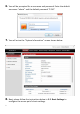
V-1-4. Windows 8 1. From the Windows 8 Start screen, you need to switch to desktop mode. Move your curser to the bottom left of the screen and click. 2. In desktop mode, click the File Explorer icon in the bottom left of the screen, as shown below.
3. 92 Right click “Network” and then select “Properties”.
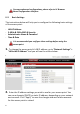
4. 5. 93 In the window that opens, select “Change adapter settings” from the left side. Choose your connection and right click, then select “Properties”.
6. Select “Internet Protocol Version 4 (TCP/IPv4) and then click “Properties”. 7. Select “Use the following IP address”, then input the following values: IP address: 192.168.2.10 Subnet Mask: 255.255.255.0 Click ‘OK’ when finished.
V-1-5. 1. Mac Have your Macintosh computer operate as usual, and click on “System Preferences” 2. In System Preferences, click on “Network”. 3. Click on “Ethernet” in the left panel. 4. 95 Open the drop-down menu labeled “Configure IPv4” and select “Manually”.
5. 96 Enter the IP address 192.168.2.10 and subnet mask 255.255.255.0. Click on “Apply” to save the changes.
V-1-6. Glossary Default Gateway (Access point): Every non-access point IP device needs to configure a default gateway’s IP address. When the device sends out an IP packet, if the destination is not on the same network, the device has to send the packet to its default gateway, which will then send it out towards the destination. DHCP: Dynamic Host Configuration Protocol. This protocol automatically gives every computer on your home network an IP address.
A network mask is also a 32-bit binary pattern, and consists of consecutive leading 1’s followed by consecutive trailing 0’s, such as 11111111.11111111.11111111.00000000. Therefore sometimes a network mask can also be described simply as “x” number of leading 1’s. When both are represented side by side in their binary forms, all bits in the IP address that correspond to 1’s in the network mask become part of the IP network address, and the remaining bits correspond to the host ID.
Application Protocol Port Number Telnet TCP 23 FTP TCP 21 SMTP TCP 25 POP3 TCP 110 H.323 TCP 1720 SNMP UCP 161 SNMP Trap UDP 162 HTTP TCP 80 PPTP TCP 1723 PC Anywhere TCP 5631 PC Anywhere UDP 5632 Access point: A access point is an intelligent network device that forwards packets between different networks based on network layer address information such as IP addresses. Subnet Mask: A subnet mask, which may be a part of the TCP/IP information provided by your ISP, is a set of four numbers (e.g. 255.255.255.
V-2. Hardware Specification MCU/RF Qualcomm IPQ4018 PHY/Switch Qualcomm QCA8072 Memory DDR3 256MB Flash 32MB Physical Interface -LAN: 10/100/1000 Gigabit Ethernet with PoE support 802.3af (PD In) -Reset Button -DC Power Jack Power Power over Ethernet, IEEE 802.3af Requirement DC : 12V ⎓ 1A Antenna Internal Antenna Others Internal Buzzer (Find me) V-3.
COPYRIGHT Copyright © 2015 by this company. All rights reserved.
Federal Communication Commission Interference Statement This equipment has been tested and found to comply with the limits for a Class B digital device, pursuant to Part 15 of FCC Rules. These limits are designed to provide reasonable protection against harmful interference in a residential installation. This equipment generates, uses, and can radiate radio frequency energy and, if not installed and used in accordance with the instructions, may cause harmful interference to radio communications.