Copyright© by Edimax Technology Co, LTD. all rights reserved.
Federal Communication Commission Interference Statement FCC Part 68 This equipment complies with Part 68 of the FCC Rules. On the bottom of this equipment is a label that contains the FCC Registration Number and Ringer Equivalence Number (REN) for this equipment. You must provide this information to the telephone company upon request. The REN is useful to determine the quantity of devices you may connect to the telephone line and still have all of those devices ring when your number is called.
this equipment from the network until the problem has been corrected or you are sure that the equipment is not malfunctioning. This equipment may not be used on coin service provided by the telephone company. Connection to party lines is subject to state tariffs. Installation This device is equipped with a USOC RJ11C connector. FCC Part 15 This equipment has been tested and found to comply with the limits for a Class B digital device, pursuant to Part 15 of FCC Rules.
FCC Caution This equipment must be installed and operated in accordance with provided instructions and a minimum 20 cm spacing must be provided between computer mounted antenna and person’s body (excluding extremities of hands, wrist and feet) during wireless modes of operation. This device complies with Part 15 of the FCC Rules.
R&TTE Compliance Statement This equipment complies with all the requirements of DIRECTIVE 1999/5/EC OF THE EUROPEAN PARLIAMENT AND THE COUNCIL of March 9, 1999 on radio equipment and telecommunication terminal Equipment and the mutual recognition of their conformity (R&TTE). The R&TTE Directive repeals and replaces in the directive 98/13/EEC (Telecommunications Terminal Equipment and Satellite Earth Station Equipment) As of April 8, 2000.
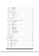
Contents 1. INTRODUCTION ....................................................... 1 1.1. 1.2. 1.3. 1.4. FEATURES ........................................................................... 2 MINIMUM REQUIREMENTS .................................................. 3 PACKAGE CONTENT ............................................................ 3 HARDWARE PLACEMENT .................................................... 4 1.4.1. 1.4.2. Rear Panel ...................................................................
5.2.3.2. DHCP Relay...................................................................................... 48 5.2.3.3. DHCP Server .................................................................................... 49 5.2.3.4. 5.2.3.5. ARP Table ......................................................................................... 52 Bridging ............................................................................................ 52 5.2.4. Wireless .............................................
6. TROUBLESHOOTING .......................................... 102 7. GLOSSARY .............................................................
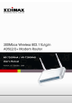
1. Introduction Congratulations on purchasing Edimax AR-7266WnA (AR-7266WnB) 300Mbps Wireless N ADSL2/2+ Router. This router is a cost-effective ADSL2/2+ router, with the combination of an ADSL2/2+ modem, router, Ethernet network switch and wireless access point, you can surf the Internet through your ADSL2/2+ ADSL connection without investing other devices. This router can support downstream transmission rates of up to 24Mbps and upstream transmission rates of up to 1Mbps.
1.1. Features ADSL2/2+ Compliance • Support downstream rates of up to 24Mbps and upstream rates of up to 1Mbps. • Compliant to ITU-T G.992.1 (G.dmt), G.992.2 (G.lite), G.992.3 (ADSL2), G.992.4 (splitterless ADSL2), G.992.5 (ADSL2+) for Annex A, B. (Annex A and B are supported in different H/W platform) • Multiple Protocols over AAL5 (RFC 1483/2684). • PPP over AAL5 (RFC 2364). PPP over Ethernet (RFC 2516). • Supports 802.11b/g/n Wireless Access Point • Complies with IEEE 802.11b/g/n standard.
1.2. Minimum Requirements The following devices are necessary to configure and use the ADSL2+ Router: • A PC with Pre-installed Ethernet Adapter (Required) and a Web-Browser (Internet Explorer 4.0 or higher) • • RJ-45 Ethernet crossover cable (Included in the package) RJ-11 (ADSL Ready) phone Line 1.3.
1.4. Hardware Placement 1.4.1. Rear Panel Item Name Description Antenna A/B These antennas are 3dBi dipole antennas. Radio ON/OFF Switch the button to activate or deactivate the wireless functions. Reset / WPS Reset the router to factory default settings (clear all settings) or start WPS function. Press this button and hold for 10 seconds to restore all settings to factory defaults, and press this button for less than 5 seconds to start WPS function.
LED Light Status Description POWER (Green) On Router is switched on and correctly powered. WLAN (Yellow) ADSL (Green) On Wireless LAN WPS is on. Off Wireless LAN is disabled Blinking Wireless traffic is transmitting or receiving On Connected to an ADSL DSLAN successfully LAN LNK/ACT (Port 1-4) Blinking ADSL line is not connect to internet. On The LAN cable is connected to the router Off No network connection.
2. Hardware Installation Step 1. Connect the ADSL Line Use the supplied RJ-11 telephone cable, connect the router from the ADSL port to your telephone socket with an ADSL micro filter plugged in. Step 2. Connect the router to your LAN network Connect the router to your PC, hub or switch by attached the Ethernet cable to the LAN port of the router. Step 3. Connect the Power Adapter to the Router Connect the power adapter to the power jack on the rear panel of the router and switch on the power. Step 4.
3. Setup Wizard 3.1. Getting Started Before you start, please check the following items: 1. Please make sure that you have connected the ADSL cable to the router correctly. When the ADSL cable is worked normally, the ADSL LED will be on. 2. Uninstall all of dial up programs if you have installed previously for the USB modem or other dial up devices. 3. It is recommended to configure the router through the Ethernet cable before you have set the wireless functions correctly.
The wizard will guide you to setup “ Internet Connection” , “ ESSID “ , Wireless security “ and “ Firmware Upgrade “ .
9
Please choose the product type which you bought . The default password is “ 1234 “ .
Please select your country and ISP .If the country or ISP is not listed , please select “Others” from the list. Click” Next “ to finish all configurations of Internet Connection , Wireless setting and Firmware Upgrade . 3.3. Manually Set ISP If you cannot find the ISP from the wizard, please follow the procedures below to set the ISP settings manually.
RFC1483 Bridged VPI/VCI, VC-based/LLC-based multiplexing to use Bridged Mode. RFC1483 Routed VPI/VCI, VC-based/LLC-based multiplexing, IP Address, Subnet Mask, Gateway Address, and Domain Name System (DNS) IP Address (It is a fixed IP Address). 1. Please select “Other”. 2. Please check with your ISP the connection type of the ADSL line. Select the Connection Type and click “Next”.
4. IP Address Setting If you lost the CD-ROM or you prefer the traditional web setup, please follow the procedures of chapter 4 and chapter 5 to configure the router. Using the router to get into the Internet, the PCs in the network must have Ethernet adapter installed and be connected to the router either directly or through a hub or switch. The TCP/IP protocol of each PC has to been installed and the IP Address of each PC has to be set in the same subnet as the router.
3. Check your list of Network Components. You should see Internet Protocol Version 4 (TCP/IPv4) on your list. Select it and click the Properties button. 4. In the Internet Protocol Version 4 (TCP/IPv4) Properties window, select Obtain an IP address automatically and Obtain DNS server address automatically as shown on the following screen. 5. Click OK to confirm the setting. Your PC will now obtain an IP address automatically from your router’s DHCP server.
1. Click the Start button and select Control Panel and then double click Network Connections. The Network Connections window will appear. 2. Right click on the Local Area Connection icon and select Properties. The Local Area Connection window will appear. 3. Check your list of Network Components. You should see Internet Protocol [TCP/IP] on your list. Select it and click the Properties button. 4.
Note: Please make sure that the router’s DHCP server is the only DHCP server available on your LAN. Windows 2000 1. Click the Start button and select Settings, then click Control Panel. The Control Panel window will appear. 2. Double-click Network and Dial-up Connections icon. In the Network and Dialup Connection window, double-click Local Area Connection icon. The Local Area Connection window will appear. 3. In the Local Area Connection window, click the Properties button. 4.
6. Click OK to confirm the setting. Your PC will now obtain an IP address automatically from your ADSL Router’s DHCP server. Note: Please make sure that the router’s DHCP server is the only DHCP server available on your LAN.
18
5. Web Management Configuration Once you have configured your PCs to obtain an IP address automatically, the router’s DHCP server will automatically give your LAN clients an IP address. By default the router’s DHCP server is enabled so that you can obtain an IP address automatically. To see if you have obtained an IP address, see Appendix A. Once your PC has obtained an IP address from your router, enter the default IP address 192.168.2.
Quick Setup (Section 5.1) The Quick Setup Wizard provides only the necessary configurations to connect your ADSL router to your Internet Service Provider (ISP). General Setup (Section 5.2) The ADSL router supports advanced functions like Virtual Server, Access Control, Hacker Attack Detection and DMZ. We highly recommend you keep the default settings. Status (Section 5.
5.1. Quick Setup The Quick Start section is designed to get you using the router as quickly as possible. Before configuring the router, please check with your ISP (Internet Service Provider) what kind of the service is provided such as PPPoE, PPPoA or RFC1483/2684. Gather the information as illustrated in the following table and keep it for reference. PPPoE VPI/VCI, VC-based/LLC-based multiplexing, Username, Password (and Service Name).
2. Please select the country where you are in and then the ISP (Internet Service Provider) of your ADSL service. 3. Enter the Username and Password which your ISP has provided to you if it is needed. Click “Finish” to save the settings.
4. Click “Commit and Reboot” to reboot the router.
5.2. General Setup Please start your web browser and log onto the web management interface of the router, then click ‘General Setup’ button on the left menu, or click ‘General Setup’ link at the upper-right corner of web management interface. 5.2.1. System This page includes the basic configuration tools for the ADSL router's remote management access function. 5.2.1.1. Time Zone The Time Zone allows your router to set its time; especially for recording System Log.
Time Zone Select Select the time zone of the country you are currently in. The router will set its time based on your selection. Enable SNTP client Check the box to enable router to update time from update SNTP server. SNTP server The IP address or the host name of the SNTP server. You can select from the list or set it manually. When you finish, click ‘Apply Changes’.
When you finish, click ‘Apply Changes’. If the password you typed in ‘New Password’ and ‘Confirmed Password’ field are not the same, you’ll see the following message: Please retype the new password again when you see above message. If you see the following message: It means the content in ‘Current Password’ field is wrong, please click ‘OK’ to go back to previous menu, and try to input current password again.
If the current and new passwords are correctly entered, after you click ‘Apply’, you’ll be prompted to input your new password: Please use new password to enter web management interface again, and you should be able to login with new password. 5.2.1.3. Remote Management The Remote Access function can secure remote host access to your router from LAN and WAN interfaces for some services provided by the router. These services include Telnet, FTP, TFTP, HTTP, SNMP and PING.
Parameter LAN Description Check/un-check the services on the LAN column to allow/unallow the services access from LAN side. WAN Check/un-check the services on the WAN column to allow/unallow the services access from WAN side. WAN Port This field allows the user to specify the port of the corresponding to the service.
Press ‘Continue’ to save the settings made and back to web management interface; press ‘Apply’ to save the settings made and restart the router so the settings will take effect after it reboots. 5.2.1.4. SNMP Simple Network Management Protocol (SNMP) is a troubleshooting and management protocol that uses the UDP protocol on port 161 to communicate between clients and servers. The router can be managed locally or remotely by SNMP protocol.
Parameter SNMP Description Select “Disable” or “Enable” to disable or enable the SNMP feature. System Description Enter the system description of the router. System Contact Enter the contact person and/or contact information for the router. System Name Assign an administratively name for the router. System Location The physical location of the router. System Object ID It is the vendor object identifier.
Press ‘Continue’ to save the settings made and back to web management interface; press ‘Apply’ to save the settings made and restart the router so the settings will take effect after it reboots. 5.2.2. WAN Use the WAN Settings screen if you have already configured the Quick Setup Wizard section and you would like to change your Internet connection type. The WAN Settings screen allows to specify the type of WAN port connect you want to establish with your ISP.
Before configuring the router, please check with your ISP (Internet Service Provider) what kind of the service is provided such as PPPoE, PPPoA or RFC1483/2684. Gather the information as illustrated in the following table and keep it for reference. PPPoE VPI/VCI, VC-based/LLC-based multiplexing, Username, Password (and Service Name). PPPoA VPI/VCI, VC-based/LLC-based multiplexing, Username, Password. RFC1483 Bridged VPI/VCI, VC-based/LLC-based multiplexing to use Bridged Mode.
Parameter Description VPI VPI is a virtual path determines the way an ATM cell should be routed. The VPI is an 8-bit (in UNI) or 12-bit (in NNI) number that is included in the header of an ATM cell. The valid range for the VPI is 0 to 255. Enter the VPI assigned by the ISP. VCI VCI is the label given to an ATM VC to identify it and determine its destination. The VCI is a 16-bit number that is included in the header of an ATM cell. The valid range for the VCI is 32 to 65535.
Encapsulation Please check with your ISP the method of multiplexing. Channel Mode There are five kinds of channel modes you can select for ADSL connection. Please check with your ISP the method of the ADSL connection. Enable NAPT Enable or disable NAPT. NAPT, an Internet standard that enables a local-area network (LAN) to use one set of IP addresses for internal traffic and a second set of addresses for external traffic.
Idle Time (ms) “Idle Time” is set to stop the connection when the network traffic is not sending or receiving after an idle time. WAN IP Setting Type Fixed IP – Set the static IP Address to the router. Please enter the IP Address your ISP has assigned. DHCP – To get the IP Address from the ISP directly. Local IP Address Set the IP Address obtained from your ISP. Remote IP Address Enter the remote IP Address assigned by your ISP. Subnet Mask Enter the Subnet Mask assigned by your ISP.
Delete Selected If you want to delete a specific VC channel entry, check the ‘select’ box of the VC channel you want to delete, then click ‘Delete Selected’ button. Enable Auto-PVC Search Check the box and ‘Apply’ button to enable auto PVC search function. VPI VPI is a virtual path determines the way an ATM cell should be routed. VCI VCI is the label given to an ATM VC to identify it and determine its destination. Add/Delete These buttons are for you to maintain the Current AutoPVC Table.
Parameter Description VPI VPI is a virtual path determines the way an ATM cell should be routed. The VPI is an 8-bit (in UNI) or 12-bit (in NNI) number that is included in the header of an ATM cell. The valid range for the VPI is 0 to 255. Enter the VPI assigned by the ISP. VCI VCI is the label given to an ATM VC to identify it and determine its destination. The VCI is a 16-bit number that is included in the header of an ATM cell. The valid range for the VCI is 32 to 65535.
depending on the availability of user information. Statistical multiplexing is provided to make optimum use of network resources. Multimedia e-mail is an example of nrtVBR. rtVBR (real time Variable Bit Rate) – This class is similar to nrtVBR but is designed for applications that are sensitive to cell-delay variation. Examples for real-time VBR are voice with speech activity detection (SAD) and interactive compressed video.
Press ‘Continue’ to save the settings made and back to web management interface; press ‘Apply’ to save the settings made and restart the router so the settings will take effect after it reboots. 5.2.2.3. ADSL Setting The page allows you to select any combination of DSL modes.
Parameter Description ADSL modulation Choose preferred ADSL standard protocols. AnnexL Option Enable/Disable ADSL2/ADSL2+ Annex L capability. AnnexM Option Enable/Disable ADSL2/ADSL2+ Annex M capability. ADSL Capability Bitswap Enable – Enable/Disable bitswap capability. SRA Enable – Enable/Disable SRA (seamless rate adaptation) capability. ADSL Tone Choose tones to be masked. The masked tones will not carry any data.
IP address. This page is used to select the way to obtain the IP addresses of the DNS servers. Parameter Description Attain DNS Select this item if you want to use the DNS servers Automatically obtained from ISP. Set DNS Manually Select this item to specify up to three DNS IP addresses. When you finish, click ‘Apply Changes’.
5.2.2.5. DDNS Dynamic DNS (DDNS) allows you to map the static domain name to a dynamic IP address. You must get an account, password and your static domain name from the DDNS service providers. Parameter Description Enable Check the box to enable DDNS function. DDNS Provider Select your DDNS service provider here. This router supports DynDNS and TZO service providers Host Name Enter the domain name you’ve obtained from DDNS service provider.
Password Enter the password assigned by the DDNS service provider. TZO Settings Email Enter the Email account that your DDNS service provider assigned to you. Key Enter the password that your DDNS service provider assigned to you. Add/Modify/Remove These buttons are for you to maintain the DDNS table.- Dynamic DDNS Table The DDNS you have configured will be added to the list. When you finish, click ‘Apply Changes’.
is no need to share routes, because all Internet data from the network is sent to the same ISP gateway. You may want to configure RIP if any of the following circumstances apply to your network: z Your home network setup includes an additional router or RIP-enabled PC (other than the ADSL Router). The ADSL Router and the router will need to communicate via RIP to share their routing tables. z Your network connects via the ADSL line to a remote network, such as a corporate network.
feature. Receive Mode Indicate the RIP version in which information must be passed to the DSL device in order for it to be accepted into its routing table. Send Mode Indicate the RIP version this interface will use when it sends its route information to other devices. RIP Config Table The RIP you have configured will be listed in the table. If you want to delete some settings, please select the settings and click “Delete Selected”. When you finish, click ‘Apply Changes’.
Parameter Description Interface Name The interface name is “br0”. IP Address Enter the IP Address of the ADSL router for the local user to access the router’s web page. By default, the IP Address is 192.168.2.1. Subnet Mask Enter the Subnet Mask of the ADSL router. By default, the Subnet Mask is 255.255.255.0. Secondary IP Assign second IP address to LAN. IGMP Snooping Enable/disable the IGMP snooping function for the multiple bridged LAN ports.
performance of the network. Ethernet to Enable/disable the ‘Ethernet to Wireless Blocking’, when this Wireless function is enabled, the traffic between Ethernet and wireless Blocking interfaces is not allowed. When you finish, click ‘Apply Changes’. You’ll see the following message displayed on web browser: Press ‘Continue’ to save the settings made and back to web management interface; press ‘Apply’ to save the settings made and restart the router so the settings will take effect after it reboots.
5.2.3.2. DHCP Relay Some ISPs perform the DHCP server function for their customers’ home/small office network. In this case, you can configure this device to act as a DHCP relay agent. When a user’s computer on your network requests Internet access, the router contacts your ISP to obtain the IP configuration, and then forward that information to the computer. Parameter Description DHCP Server Address Specify the IP address of your ISP’s DHCP server.
When you finish, click ‘Apply Changes’. You’ll see the following message displayed on web browser: Press ‘Continue’ to save the settings made and back to web management interface; press ‘Apply’ to save the settings made and restart the router so the settings will take effect after it reboots. 5.2.3.3. DHCP Server When the DHCP server is enabled, the router will automatically give your LAN clients an IP address. If the DHCP is not enabled then you’ll have to manually set your LAN client’s IP addresses.
Parameter Description LAN IP Address The current IP Address of the router. Subnet Mask The current Subnet Mask of the router. IP Pool Range You can select a particular IP address range for your DHCP server to issue IP addresses to your LAN Clients. By default, the IP range is starting from IP 192.168.2.100 to 192.168.2.200. Parameter Description Show Client Click this button and a table is displayed. You can know the assigned IP address, MAC address and time expired for each DHCP leased client.
Subnet Mask Enther the subnet mask to LAN clients. Max Lease Time In the Lease Time setting you can specify the time period that the DHCP Server lends an IP address to your LAN clients. The DHCP will change your LAN client’s IP address when this time threshold period is terminated. Domain Name A user-friendly name that refers to the group of hosts (subnet) that will be assigned addresses from this pool. Gateway Address The IP address of the ADSL router.
5.2.3.4. ARP Table ARP is the Address Resolution Protocol and its job is to match MAC address to IP address and obviously vice versa - to match IP addresses to MAC addresses. This page lists the IP Addresses and the match MAC Addresses in the network. 5.2.3.5. Bridging You can enable/disable Spanning Tree Protocol and set MAC address aging time in this page.
Ageing Time Set the Ethernet address ageing time. After the ageing time of not having seen a frame coming from a certain address, the bridge will time out (delete) and do not forward the frame. 802.1d Spanning Tree Enable/disable the spanning tree protocol. When this feature is enabled, this router will use the spanning tree protocol to prevent from network loop happened in the network (LAN Side). When you finish, click ‘Apply Changes’.
5.2.4. Wireless ADSL router builds a wireless LAN and can let all IEEE 802.11b, IEEE 801.11g or IEEE 802.1n wireless stations connect to your Intranet. It supports WEP, WPA and WPA2 encryption to enhance the security of your wireless network. It also support WPS function for you to easy setup the wireless connection between the ADSL router with other stations. 5.2.4.1. Basic Settings This section provides the wireless network settings for your router. You can enable the wireless AP function here.
Parameter Description Disable Wireless LAN Check it to deactivate the wireless function of the router. Interface When it is activated, the router will not be an access point for other wireless clients to connect wirelessly. Band Please select the radio band from one of the following options. 2.4GHz(B): 2.4GHz band, only allows 802.11b wireless network client to connect this router (maximum transfer rate 11Mbps). 2.4 GHz (G): 2.4GHz band, only allows 802.
(maximum transfer rate 11Mbps for 802.11b clients, and maximum 54Mbps for 802.11g clients). 2.4 GHz (N): 2.4GHz band, only allows 802.11n wireless network client to connect this router (maximum transfer rate 150Mbps). 2.4 GHz (G+N):2.4GHz band, only allows 802.11g and 802.11n wireless network client to connect this router (maximum transfer rate 54Mbps for 802.11g clients, and maximum 150Mbps for 802.11n clients). 2.4 GHz (B+G+N): 2.4GHz band, allows 802.11b, 802.11g, and 802.
Channel Number It is the radio channel used by the wireless LAN. All devices in the same wireless LAN should use the same channel. Please select the country you are located and designate a channel that the router will use. If you want to let the router automatically to find an available channel with the highest signal strength, please select “Auto”. Radio Power (mW) Set the maximum output power of the router. The higher output power, the wider coverage range.
Parameter Description Authentication Type There are three authentication types: "Open System", "Shared Key" and "Auto". Open System: Open System authentication is not required to be successful while a client may decline to authenticate with any particular other client. Shared Key: Shared Key is only available if the WEP option is implemented. Shared Key authentication supports authentication of clients as either a member of those who know a shared secret key or a member of those who do not. IEEE 802.
WEP privacy mechanism. Auto: Auto is the default authentication algorithm. It will change its authentication type automatically to fulfill client’s requirement. Fragmentation Fragment Threshold specifies the maximum size of Threshold packet during the fragmentation of data to be transmitted. If you set this value too low, it will result in bad performance. Enter a value from 256 to 2346. RTS Threshold This value should remain at its default setting of 2347.
Preamble Type The Preamble Type defines the length of the CRC (Cyclic Redundancy Check) block for communication between the router and wireless stations. Make sure to select the appropriate preamble type. Note that high network traffic areas should use the “Short Preamble”. CRC is a common technique for detecting data transmission errors. Broadcast SSID If this option is enabled, the router will automatically transmit the network name (SSID) into open air at regular interval.
will increase network efficiency. When you finish, click ‘Apply Changes’. You’ll see the following message displayed on web browser: Press ‘Continue’ to save the settings made and back to web management interface; press ‘Apply’ to save the settings made and restart the router so the settings will take effect after it reboots. 5.2.4.3. Security This router provides complete wireless LAN security functions, include WEP, IEEE 802.1x, IEEE 802.1x with WEP, WPA with pre-shared key and WPA with RADIUS.
Parameter Description Encryption You can choose “None” to disable the encryption or select “WEP”, “WPA(TKIP)”, “WPA2(AES)” or “WPA2 Mixed” mode for security. When “WEP” is enabled, please click “Set WEP Key” button to choose the default key and set the four sets of WEP keys. WEP –WEP is less level of security than WPA. WEP supports 64-bit and 128-bit key lengths to encrypt the wireless data. WPA(TKIP) – WPA uses Temporal Key Integrity Protocol (TKIP) for data encryption.
encryption. WPA Mixed – The router supports WPA (TKIP) and WPA2 (AES) for data encryption. The actual selection of the encryption methods will depend on the clients. Use 802.1x IEEE 802.1x is an authentication protocol. Every user Authentication must use a valid account to login to this wireless router before accessing the wireless LAN. The authentication is processed by a RADIUS server. Check this box to authenticates user by IEEE 802.1x. WEP-64Bits WEP is less level of security than WPA.
Shared Key Format” and “Pre-Shared Key” setting respectively. Pre-Shared Key You may select to select Passphrase (alphanumeric Format format) or Hexadecimal Digits (in the “A-F”, “a-f” and “09” range) to be the Pre-shared Key. For example: Passphrase: ”iamguest” Hexadecimal Digits: “12345abcde” Pre-Shared Key Please enter 8-63 characters as the “Pre-Shared Key”.
Parameter Wireless Access Description This router can prevent the wireless clients from Control Mode accessing the wireless network by checking the MAC Address of the clients. If you enable this function, please set the MAC Address of the wireless clients that you want to filter. Disable – Disable this function. Allow Listed – Only allow the wireless clients with the MAC Address you have specified can access to the router.
filtering control. Current Access Control If you want to remove some MAC address from the List "Current Access Control List ", select the MAC addresses you want to remove in the list and then click "Delete Selected". If you want remove all MAC addresses from the table, just click "Delete All" button. Click "Reset" will clear your current selections. When you finish, click ‘Apply Changes’.
Parameter Description Disable WPS Check to disable the Wi-Fi protected Setup. WPS Status When AP’s settings are factory default (out of box), it is set to open security and un-configured state. “WPS Status” will display it as “UnConfigured”. If it already shows “Configured”, some registrars such as Vista WCN will not configure AP. Users will need to go to the “Backup/Restore” page and click “Reset” to reload factory default settings. Self-PIN Number “Self-PIN Number” is AP’s PIN.
registrar side needs to be supported with four-digit PIN. Regenerate PIN Click to regenerate the Self-PIN Number. Push Button Clicking this button will invoke the PBC method of WPS. Configuration It is only used when AP acts as a registrar. Start PBC Click to start the Push Button method of WPS. Reset It restores the original values. Client PIN Number It is only used when users want their station to join AP’s network. The length of PIN is limited to four or eight numeric digits.
Parameter Description IP QoS Click the radio button to enable or disable the IP QoS function. Default QoS Select the default mode of QoS from the list. IP Precedence: In QoS, a three-bit field in the ToS byte of the IP header (see RFC 791).
to classify and prioritize types of traffic. 802.1P: IEEE 802.1p is a 3 bit field within an Ethernet frame header when using tagged frames on an 802.1 network. It specifies a priority value of between 0 and 7 inclusive that can be used by Quality of Service (QoS) disciplines to differentiate traffic. Source IP The IP address of the traffic source. Source Netmask The source IP netmask. This field is required if the source IP has been entered. Source Port The source port of the selected protocol.
2.1p Select this field to mark the 3-bit user-priority field in the 802.1p header of the packet that matches this classification rule. Note that this 802.1p marking is workable on a given PVC channel only if the VLAN tag is enabled in this PVC channel. Precedence Select this field to mark the IP precedence bits in the packet that match this classification rule. TOS The IP (Internet Protocol) uses the ToS (Type of Service) field to provide an indication of the quality of service desired.
5.2.6. NAT (Network address translations) NAT (Network address translations) solve the problem if sharing a single IP address to multiple computers. Without NAT, all computers must be assigned with a valid Internet IP address to get connected to Internet, but Internet service providers only provide very few IP addresses to every user. Therefore it’s necessary to use NAT technology to share a single Internet IP address to multiple computers on local network, so everyone can get connected to Internet.
Parameter Port Forwarding Description Check this item to enable or disable the port-forwarding feature. Protocol This is the protocol type to be forwarded. You can choose to forward “TCP” or “UDP” packets only or select “Both” to forward both “TCP” and “UDP” packets. Comment Enter the comment for the setting. Enable Check this item to enable this entry. Local IP Address IP address of your local server that will be accessed by Internet.
application on the LAN side. Remote IP Address The source IP address from which the incoming traffic is allowed. Leave blank for all. Public Port The destination port number that is made open for this application on the WAN side Interface Select the WAN interface on which the port-forwarding rule is to be applied. Current Port If you want to remove the port forwarding settings from Forwarding Table the table, select the items and then click "Delete Selected".
belong to the default group, and the other four groups are all empty. It is possible to assign any interface to any group but only one group. Parameter Description Disabled/ Enabled Click the radio button to enable or disable the feature. If disabled, all interfaces belong to the default group. Interface groups To manipulate a mapping group: 1. Select a group from the table. 2.
When you finish, click ‘Apply Changes’. You’ll see the following message displayed on web browser: Press ‘Continue’ to save the settings made and back to web management interface; press ‘Apply’ to save the settings made and restart the router so the settings will take effect after it reboots. 5.2.6.3. UPNP When the UPnP function is enabled, the router can be detected by UPnP compliant system such as Windows XP.
When you finish, click ‘Apply Changes’. You’ll see the following message displayed on web browser: Press ‘Continue’ to save the settings made and back to web management interface; press ‘Apply’ to save the settings made and restart the router so the settings will take effect after it reboots. 5.2.6.4. IGMP Proxy When “IGMP Proxy” (Internet Group Management Protocol Proxy) is enabled, the router can make intelligent multicast forwarding decisions by examining the contents of each frame’s IP header.
Parameter IGMP Proxy Description Enable or disable IGMP proxy feature. Proxy Interface The upstream WAN interface is selected here. When you finish, click ‘Apply Changes’. You’ll see the following message displayed on web browser: Press ‘Continue’ to save the settings made and back to web management interface; press ‘Apply’ to save the settings made and restart the router so the settings will take effect after it reboots. 5.2.7.
Firewall contains several features that are used to deny or allow traffic from passing through the router. 5.2.7.1. IP/Port Filtering The IP/Port filtering feature allows you to deny/allow specific services or applications in the forwarding path. Parameter Description Outgoing Default Specify the default action on the LAN to WAN (Traffic to Action Internet) forwarding path.
Incoming Default Specify the default action on the WAN to LAN (Traffic Action from Internet) forwarding path. You can choose ‘Allow’ if you allow the IP Addresses listed in the following table from connecting to the Internet; choose ‘Deny’ if you deny the IP Addressed listed in the following table from connecting to the Internet. Direction Select the traffic forwarding direction: outgoing or incoming. Protocol There are 3 options available: TCP, UDP and ICMP.
"Delete All" button. When you finish, click ‘Apply Changes’. You’ll see the following message displayed on web browser: Press ‘Continue’ to save the settings made and back to web management interface; press ‘Apply’ to save the settings made and restart the router so the settings will take effect after it reboots. 5.2.7.2. MAC Filtering The MAC filtering feature allows you to define rules to allow or deny frames through the router based on source MAC address, destination MAC address, and traffic direction.
Parameter Description Outgoing Default Specify the default action on the LAN to WAN (Traffic to Action Internet) forwarding path. You can choose ‘Allow’ if you allow the IP Addresses listed in the following table from connecting to the Internet; choose ‘Deny’ if you deny the IP Addressed listed in the following table from connecting to the Internet. Incoming Default Action Specify the default action on the WAN to LAN (Traffic from Internet) forwarding path.
Rule Action Deny or allow traffic when matching this rule. Source MAC Address The source MAC address. It must be 12-digit hexadecimal format, for example: “00-d0-59-c6-12-43”. Destination MAC The destination MAC address. It must be 12-digit Address hexadecimal format, for example: “00-d0-59-c6-12-50”. Current Filter Table If you want to remove some filter rules from the "Current Filter Table", select the MAC Address you want to remove in the table and then click "Delete Selected".
Parameter Description URL Blocking Enable or disable the URL blocking function. FQDN Enter FQDN which you want to block. A FQDN is a complete DNS name. For example, “www.yahoo.com”. URL Blocking Table The FQDN settings will be listed in the table. If you want to delete some FQDN settings from the table, please select the settings and click “Delete Selected”. If you want remove all settings from the table, just click "Delete All" button.
filter. Keyword Filtering The keyword settings will be listed in the table. If you Table want to delete some keyword settings from the table, please select the settings and click “Delete Selected”. If you want remove all settings from the table, just click "Delete All" button. When you finish, click ‘Apply Changes’.
Parameter Domain Blocking Description Check this item to enable the Domain Blocking feature. Domain The blocked domain. If the URL of Taiwan Yahoo web site is tw.yahoo.com, the domain can be yahoo.com. Delete Selected/All If you want to delete a specific Domain Block entry, check the ‘select’ box of the Domain Block you want to delete, then click ‘Delete Selected’ button. If you want remove all settings from the table, just click "Delete All" button. 5.2.7.5.
You may need to define routes if your home setup includes two or more networks or subnets, if you connect to two or more ISP services, or if you connect to a remote corporate LAN. Parameter Description Enable Check to enable the selected route or route to be added. Destination The destination can be specified as the IP address of a subnet or a specific host in the subnet.
Metric Defines the number of hops between network nodes that data packets travel. The default value is 0, which means that the subnet is directly one hop away on the local LAN network. Interface The WAN interface to which a static routing subnet is to be applied. Add Route Add a user-defined destination route. Show Routes Click this button to view the router’s routing table. Static Route Table Click “Update” to update the selected destination route on the “Static Route Table”.
Parameter Description ACL Capability Enable or disable the ACL function Enable Check to enable this ACL entry Interface Select the interface domain: LAN or WAN IP Address Enter the IP address that is allowed to access the router. Subnet Mask Enter the Subnet Mask that is allowed to access the router. ACL Table The ACL settings will be listed here. You can click “Delete Selected” to delete the settings you have selected.
Press ‘Continue’ to save the settings made and back to web management interface; press ‘Apply’ to save the settings made and restart the router so the settings will take effect after it reboots. 5.2.7.7. DMZ The DMZ Host is a local computer exposed to the Internet. When setting a particular internal IP Address as the DMZ Host, all incoming packets will be checked by the firewall and NAT algorithms then passed to the DMZ Host.
When you finish, click ‘Apply Changes’. You’ll see the following message displayed on web browser: Press ‘Continue’ to save the settings made and back to web management interface; press ‘Apply’ to save the settings made and restart the router so the settings will take effect after it reboots. 5.3. Status This page displays the ADSL modem/router’s current status and settings. This information is read-only except for the PPPoE/PPPoA channel for which user can connect/disconnect the channel on demand.
5.3.1. Interface You can view statistics on the processing of IP packets on the networking interfaces. You will not typically need to view this data, but you may find it helpful when working with your ISP to diagnose network and Internet data transmission problems. To display statistics for any new data, click “Refresh”.
5.3.2. ADSL This page shows the ADSL line statistic information.
5.4.
The Tools Settings section includes the basic configuration tools, such as Back Up, Restore Configuration Settings, Upgrade System Firmware and Diagnostic Test. 5.4.1. Configuration Tools This page allows you to backup the current settings to a file or restore the settings from the file which was saved previously. Besides, you could reset the current configuration to factory defaults.
Parameter Description Save Settings to File Click Save button to save the ADSL router current configuration to a file named "config.bin" on your PC. Load Settings from File Click Browse button to search the file you have saved before and click Upload button to restore the saved configuration to the ADSL router. Restore Settings to Click Reset button if you want to force the ADSL router to Default perform a power reset and restore the original factory settings. 5.4.2.
5.4.3. Ping Once you have your router configured, you can send a ping command to the host you specify in this page. To use it, you must know the IP address of the host you are trying to communicate with and enter the IP address in the Host Address field. 5.4.4. ATM Loopback In order to isolate the ATM interface problems, you can use ATM OAM loopback cells to verify connectivity between VP/VC endpoints, as well as segment endpoints within the VP/VC.
Parameter Description Select PVC Select the PVC channel you want to do the loop-back diagnostic. Flow Type The ATM OAM flow type. The selection can be F5 Segment or F5 End-to-End. ATM uses F4 and F5 cell flows as follows: F4: used in VPs F5: used in VCs Loopback Location ID The loop-back location ID field of the loop-back cell. The default value is all 1s (ones) to indicate the endpoint of the segment or connection. Click “Go!” to save the setting to the configuration.
5.4.5. ADSL This page shows the ADSL diagnostic result. Click “Start” button to start the ADSL diagnostic.
5.4.6. Diagnostic Test The Diagnostic Test page shows the test results for the connectivity of the physical layer and protocol layer for both LAN and WAN sides.
5.4.7. Reboot Whenever you use the Web configuration to change system settings, the changes are initially placed in temporary storage. To save your change for future use, you have to click “Commit and Reboot” to reboot the router. If you have encountered some problems during the configurations, You can click the “Reset” button in the rear panel of the router over 10 seconds to reset default settings.
6. Troubleshooting 1. The LAN LED on the front panel does not light up. STEPS CORRECTIVE ACTION 1 Check the Ethernet cable connections between your ADSL2+ Router and the computer or hub. 2 Check for faulty Ethernet cables. 3 Make sure your computer’s Ethernet card is working properly. 4 If these steps fail to correct the problem, contact your local distributor for assistance. 2. The ADSL LED on the front panel does not light up.
The following procedures will help you to check the current IP Address setting of your computer. You can compare if your computer and router’s IP Addresses are in the same subnet. Step 1: Click “Start” and select “Run”. Step 2: Type in “cmd” and click “OK”. Step 3: Type ipconfig /all and click enter. z Your PC’s IP address is 192.168.2.111. z The PC’s Subnet Mask is 255.255.255.0. Your PC’s MAC Address is the one entitled Physical Address (00-00-E2-82- z C3-AD).
4. I forget my login username and/or password. STEPS CORRECTIVE ACTION 1 If you have changed the password and have now forgotten it, you will need to upload the default configuration file. This will erase all custom configurations and restore all of the factory defaults including the password. 2 Press the Reset/WPS button for over five seconds, and then release it. When the Power LED begins to blink, the defaults have been restored. 3 The default username is “admin”. The default password is “1234”.
6. Initialization of the ADSL connection failed. STEPS CORRECTIVE ACTION 1 Check the cable connections between the ADSL port and the wall jack. The ADSL LED on the rear panel of the router should be on. 2 Check VPI, VCI, type of encapsulation and type of multiplexing settings are the same as what you collected from your ISP. 3 Restart the router. If you still have problems, you may need to verify your VPI, VCI, type of encapsulation and type of multiplexing settings with the ISP. 7.
7. Glossary 10Base-T It is an Ethernet standard for Local Area Network (LAN). 10Base-T uses a twisted pair cable with maximum length of 100 meters. AAL ATM Adaptation Layer that defines the rules governing segmentation and reassembly of data into cells. Different AAL types are suited to different traffic classes. ADSL Asymmetric Digital Subscriber Line, as its name showing, is an asymmetrical data transmission technology with high traffic rate downstream and low traffic rate upstream.
CPE Customer Premises Equipment, such as ADSL router, USB modem. Default Gateway (Router) Every non-router IP device needs to configure a default gateway’s IP address. When the device sends out an IP packet, if the destination is not on the same network, the device has to send the packet to its default gateway, which will then send it out towards the destination. DHCP Dynamic Host Configuration Protocol, this protocol automatically gives every computer on your home network an IP address.
FTP File Transfer Protocol. The Internet protocol (and program) used to transfer files between hosts. Idle Timeout Idle Timeout is designed so that after there is no traffic to the Internet for a preconfigured amount of time, the connection will automatically be disconnected. ISP Internet Service Provider is a business that provides connectivity to the Internet for individuals and other businesses or organizations.
provide a sort of firewall and allow for a wider address range to be used internally without danger of conflict. Using the router’s NAT capability, you can access the Internet from any computer on your home network without having to purchase more IP addresses from your ISP. Port Network Clients (LAN PC) uses port numbers to distinguish one network application/protocol over another.
PPPoE (RFC 2516) This document describes how to build PPP sessions and encapsulate PPP packets over Ethernet. PPP over Ethernet (PPPoE) provides the ability to connect a network of hosts over a simple bridging access device to a remote Access Concentrator.
Subnet Mask A subnet mask, which may be a part of the TCP/IP information provided by your ISP, is a set of four numbers (e.g. 255.255.255.0) configured like an IP address. It is used to create IP address numbers used only within a particular network (as opposed to valid IP address numbers recognized by the Internet, which must be assigned by InterNIC). TCP/IP, UDP Transmission Control Protocol/Internet Protocol (TCP/IP) and Unreliable Datagram Protocol (UDP).
Web-based management Graphical User Interface (GUI) Many devices support a graphical user interface that is based on the web browser. This means the user can use the familiar Netscape or Microsoft Internet Explorer to Control/configure or monitor the device being managed.
Federal Communication Commission Interference Statement This equipment has been tested and found to comply with the limits for a Class B digital device, pursuant to Part 15 of FCC Rules. These limits are designed to provide reasonable protection against harmful interference in a residential installation. This equipment generates, uses, and can radiate radio frequency energy and, if not installed and used in accordance with the instructions, may cause harmful interference to radio communications.
The ETSI version of this device is also authorized for use in EFTA member states: Iceland, Liechtenstein, Norway, and Switzerland. EU Countries not intended for use None A declaration of conformity is available on www.edimax.
115