BR-6624 Load Balancing Router Manual
TABLE OF CONTENTS 1: INTRODUCTION ..............................................................................................................................1 Internet Features ..........................................................................................................................1 Other Features ..............................................................................................................................3 Package Contents ................................................
WAN Status .................................................................................................................................68 NAT Status ..................................................................................................................................69 APPENDIX A SPECIFICATIONS .......................................................................................................71 APPENDIX B WINDOWS TCP/IP SETUP .............................................................
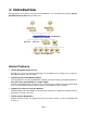
1: Introduction Congratulations on the purchase of your new Load Balancer. The Load Balancer provides Shared Broadband Internet Access for all LAN users. Figure 1-1: Load Balancer Internet Features • Shared Broadband Internet Access All LAN users can access the Internet through the Load Balancer, by sharing one (1) or two (2) Broadband modems and connections. • High-Performance Dual Modem Support The Load Balancer has two (2) WAN ports, allowing connection of two (2) Broadband modems.
• Multiple IP Address Support If your ISP allocates you multiple IP addresses, these are also supported and you can “map” IP addresses to individual PCs if desired. • Special Applications This feature allows you to use some non-standard applications, where the port number used for the response is different to the port number used by the sender. • Virtual Servers This feature allows Internet users to access Internet servers on your LAN.
Other Features • 4-Port Switching Hub The Load Balancer incorporates a 4-port 10 /100BaseT switching hub, making it easy to create or extend your LAN. • DHCP Server Support Dynamic Host Configuration Protocol provides a dynamic IP address to PCs and other devices upon request. The Load Balancer can act as a DHCP Server for devices on your local LAN. • Multi Segment LAN Support LANs containing one or more segments are supported, via The Load Balancer's built-in static routing table.
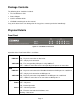
Package Contents The following items should be included: • The Load Balancer Unit • Power Adapter • Quick Installation Guide • CD-ROM containing the on-line manual. If any of the above items are damaged or missing, please contact your dealer immediately. Physical Details Front Panel Figure 1-2: Load Balancer Front Penal Operation of the Front Panel LEDs is as follows: LAN LINK/ACT ON – Physical connection or data in/out. OFF – No physical connection.
Also, some Status and Error conditions are indicated by combinations of LEDs, as shown below LED Action Condition WAN1 LINK/ACT & 10M/100M LEDs flash alternatively. Firmware Download in progress. WAN1 LINK/ACT & 10M/100M LEDs flash concurrently. MAC address not assigned.
Rear Panel Figure 1-2: Rear Panel DC 5V Connect the supplied power adapter here. WAN 2 Connect the 2nd Broadband Modem here, if available. Reset Button When pressed and released, The Load Balancer will reboot (restart) within 1 second. It resets to default over 3 seconds. LAN Ports Connect the PCs to these ports. Both 10BaseT and 100BaseT connections can be used simultaneously. Note: Any port will automatically operate as an "Uplink" port if required.
Figure 1-3: Windows TFTP utility • Enter the name of the firmware upgrade file on your PC, or click the "Browse" button to locate the file. • Enter the LAN IP address of The Load Balancer in the "Server IP" field. • Click "Download" to send the file to The Load Balancer. 3. When downloading is finished. It should then work normally, using the default settings.
2: Basic Setup Overview Basic Setup of your Load Balancer involves the following steps: 1. Attach The Load Balancer to one (1) PC, and configure it for your LAN. 2. Install your Load Balancer in your LAN, and connect the Broadband Modem or Modems. 3. Configure your Load Balancer for Internet Access. 4. Configure PCs on your LAN to use The Load Balancer. Requirements • One (1) or two (2) DSL or Cable modems, each with an Internet Access account with an ISP. • Network cables.
• You can and should set a password, using the following Admin Password screen. No Response ? • Is your PC using a Fixed IP address ? If so, you must configure your PC to use an IP address within the range 192.168.1.2 to 192.168.1.254, with a Network Mask of 255.255.255.0. See Appendix B – Windows TCP/IP Setup for details. • Check that The Load Balancer is properly installed, LAN connection is OK, and it is powered ON. 8. After the login, you will then see the Admin Password screen, as shown below.
9. Select LAN & DHCP from the menu. You will see a screen like the example below. Figure 2-3: LAN & DHCP 10. Ensure these settings are suitable for your LAN: • The default settings are suitable for many situations. • See the following table for details of each setting. 11. Save your data, then go to Step 2, Installing The Load Balancer in your LAN. Settings – LAN & DHCP LAN IP Configuration Optional Configuration • IP address - for the Load Balancer, as seen from the local LAN.
Server setting must be Disabled, and the existing DHCP server must be set to provide the IP address of the Load Balancer as the Default Gateway. DHCP Configuration DHCP Free List • LAN Any IP –By default is disabled. If you enable “LAN Any IP”, that means no matter what static IP address hold on the client (your PC). The client has do not need to change the IP address, even though it has different IP segment than LAN segment. It still can access Internet through NAT.
2. Installing The Load Balancer in your LAN Figure 2-4: Installation Diagram 1. Ensure The Load Balancer and the DSL/Cable modem are powered OFF. Leave the modem or modems connected to their data line. 2. Connect the Broadband modem or modems to The Load Balancer. • If using only one (1) Broadband modem, connect it to the "WAN 1" port. • Use the cable supplied with your DSL/Cable modem. If no cable was supplied, use a standard cable. 3.
• For each PC connected to the LAN ports, the corresponding LAN LED (either 10 or 100) should be ON. 3. Configuring The Load Balancer for Internet Access Select Primary Setup from the menu, to see a screen like the example below. • Configure WAN 1 and/or WAN 2 as required. • For any of the following situations, refer to Chapter 3: Advanced Port Setup for any further configuration, which may be required.
Settings – Primary Setup Connection • Interface – Select which WAN (WAN1 or WAN2) to be setup. • Connection Mode Select the appropriate setting: • • Enable – Select this if you have connected a broadband modem to this port. • Disable – Select this if there is no broadband modem connected to this port. • Backup – Use this if you have a broadband modem on each port, and wish to normally use only one. Select Enable for the primary port, and Backup for the secondary port.
Optional • Host name – This is required by some ISPs. If your ISP provided a Host Name, enter it here. Otherwise, you can use the default value. • Domain name – This is required by some ISPs. If your ISP provided a Domain Name, enter it here. Otherwise, you can use the default value. • MAC address – Some ISP's record your MAC address (also called "Physical address" or "Network Adapter address"). If so, you can enter the MAC address expected by your ISP in this field.
4: Configure PCs on your LAN Overview For each PC, the following may need to be configured: • TCP/IP network settings • Internet Access configuration TCP/IP Settings If using the default Load Balancer settings, and the default Windows 95/98/ME/2000/XP TCP/IP settings, no changes need to be made. Just start (or restart) your PC. • By default, The Load Balancer will act as a DHCP Server, automatically providing a suitable IP Address (and related information) to each PC when the PC boots.
7. Select "Set up my connection manually" and click “Next”. 8. Check "Connect using a broadband connection that is always on" and click Next. 9. Click Finish to close the New Connection Wizard. Setup is now completed. Accessing AOL To access AOL (America On Line) through The Load Balancer, the AOL for Windows software must be configured to use TCP/IP network access, rather than a dial-up connection. The configuration process is as follows: • Start the AOL for Windows communication software.
• Set your Default Gateway to the IP Address of The Load Balancer. • Ensure your DNS (Name server) settings are correct. To act as a DHCP Client (recommended) The procedure below may vary according to your version of Linux and X -windows shell. 1. Start your X Windows client. 2. Select Control Panel - Network 3. Select the "Interface" entry for your Network card. Normally, this will be called "eth0". 4. Click the Edit button, set the "protocol" to "DHCP", and save this data. 5.
3: Advanced Port Setup Overview • Port Options contains some options, which can be set on either or both WAN ports. For most situations, the default values are satisfactory. • Load Balance screen is only functional if you are using both WAN ports. It allows you to determine the proportion of WAN traffic sent through each port. • Advanced PPPoE setup is required if you wish to use multiple sessions on one or both of the WAN ports. It can also be used to manually connect or disconnect a PPPoE session.
Settings – Port Options Interface Connection Health Check • WAN Ports – To select the WAN port for option settings • MTU –The largest amount of data that can be transferred across a given physical network. Ethernet limits transfers to 1500 octets of data. Normally, you should leave this value at its default value. Change it only if the ISP is providing a MTU that is not optimal • Method – ICMP: The health check is performed by sending an ICMP echo request packet to the specific destination.
Transparent Bridge Option (for all interface) • Traffic Management – Strict binding: Traffic from bridge hosts (eg. transparent to WAN1) can only go through that a specified WAN (eg. WAN1) interface. Loose binding: Traffic from bridge hosts (eg. transparent to WAN1) can go through an alternative WAN (eg. WAN2) interface when binded interface (eg. WAN1) is down. It acts like a failover mechanism for Transparent Bridge mode. Load Balancing: Traffic from bridge hosts (eg.
Load Balance This screen is only operational if using Internet connections on both WAN ports. Figure 3-2: Load Balance These settings are only functional if using both WAN ports. If using both WAN ports, these settings determine the proportion of traffic sent over each port.
Settings – Load Balance Load Balance Configuration • Enable – This will allow you enable or disable the load-balancing feature. • Load Balancing Base On – Select the desired option to measure the traffic load. 1. Bytes Tx + Rx: The link with the least number of bytes transmitted through the WAN port. 2. Packets Tx + Rx: The link with the least number of packets transmitted through the WAN port. 3. Sessions Established: The link with the least number of sessions built on the WAN port. 4.
Advanced PPPoE The screen is required in order to use multiple PPPoE sessions on the same WAN port. It can also be used to manually connect or disconnect a PPPoE session.
Settings – Advanced PPPoE Select WAN Port & Session WAN IP Account Options PPPoE Auto Dialup Connection Status • Select WAN Port & PPPoE Session – Select the desired WAN port and PPPoE session from the pull-down menu and click the Select button. The screen will then show the data for the selected Port/Session. Input the required data and click Update to save your changes • PPPoE Session MTU –The Maximum Transmission Unit for the PPPoE session. The default value is 1492 bytes.
Advanced PPTP This screen is only useful if using the PPTP connection method. Figure 3-4: Advanced PPTP Settings – Advanced PPTP WAN Port WAN IP Account Used if you choose PPTP on Static/Dynamic IP as your connection setup from primary setup.
PPTP Auto Dialup Connection Status • Auto Dialup –To enable or disable auto dialup for a PPTP connection. If you decide not to use auto dialup or auto disconnect, then you have to connect/disconnect manually. • Disconnect After Idle –To decide the timeout for disconnecting when there is no traffic on the connection. Enter -1 to keep the connection always alive. Enter 0 to enable 'dial on demand by trigger'. • Echo Time –To determine how often an Echo request is sent to the PPTP server.
4: Advanced Configuration Overview The following advanced features are provided. • Host IP Setup • Routing • Virtual Servers • Special Applications • Dynamic DNS • Multi DMZ • UpnP • NAT Setup • ARP Statp • Advanced Features This chapter contains details of the configuration and use of each of these features. Host IP Setup This feature is used in the following situations: • You have Multi-Session PPPoE, and wish to bind each session to a particular PC on your LAN.
Figure 4-1: Host IP Setup Settings – Host IP Setup Host Network Identity This section identifies each Host (PC) • Host name – Enter a suitable name. Generally, you should use the "Hostname" (computer name) defined on the Host itself. • MAC Address – Also called Physical Address or Network Adapter Address. Enter the MAC address of this host. • Select Group – Select the group you wish to put this host into.
Host Network Binding • Bind WAN port/Session – Select Enable if you wish to associate this PC with a particular PPPoE Session. All traffic for that PC will then use the selected PPPoE port and session. • Binding Method – Suppose your PC is bound to WAN1 port, now you are selecting “Strict Binding”. If WAN1 port is disconnected, your packets cannot go out through WAN2 port, if WAN2 port is still alive.
Note: If there is an entry or entries in the Routing table with an Index of zero (0), these are System entries. You cannot modify or delete these entries. Settings – Routing Dynamic Routing Static Routing Routing List • RIP v2 – RIP is a dynamic routing protocol which is used to direct traffic over the network. Disable it if you don't need to use it. • LAN, WAN1, WAN2 – If enabled, any WAN or LAN can execute RIP function.
Static Routing - Example Segment 1 (192.168.2.xx) (192.168.2.80) (192.168.1.100) Segment 0 (192.168.1.xx) Router A (192.168.1.1) Router B (192.168.2.90) (192.168.3.70) Segment 2 (192.168.3.xx) Figure 4-3: Routing Example For The Load Balancer Gateway's Routing Table For the LAN shown above, with 2 routers and 3 LAN segments, The Load Balancer requires 2 entries as follows. Entry 1 (Segment 1) Destination IP Address 192.168.2.0 Network Mask 255.255.255.0 Gateway IP Address 192.168.1.
For Router B's Default Route Destination IP Address 0.0.0.0 Network Mask 0.0.0.0 Gateway IP Address 192.168.2.80 Interface LAN Metric 3 Virtual Servers This feature allows you to make Servers on your LAN accessible to Internet users. Normally, Internet users would not be able to access a server on your LAN because: • Your Server's IP address is only valid on your LAN, not on the Internet. • Attempts to connect to devices on your LAN are blocked by the firewall in The Load Balancer.
Connecting to the Virtual Servers Once configured, anyone on the Internet can connect to your Virtual Servers. They must use The Load Balancer's Internet IP Address (the IP Address allocated by your ISP). e.g. http://205.20.45.34 ftp://205.20.45.34 • To Internet users, all virtual Servers on your LAN have the same IP Address. This IP Address is allocated by your ISP. • This address should be static, rather than dynamic, to make it easier for Internet users to connect to your Servers.
Settings – Virtual Server Virtual Server Configuration Virtual Server List • Enable – To activate or deactivate the current entry. • Server Name – A unique name for identifying the virtual server. • Protocol – Select the protocol (either TCP or UDP) used by the server software. • IP Address – LAN: Enter the IP address of the server on the device's LAN side. The hosts used as Virtual Servers need static IP addresses or reserved IP addresses. WAN: The WAN port that the virtual server is bound on.
Special Applications If you use Internet applications, which have non-standard connections or port numbers, you may find that they do not function correctly because they are blocked by the firewall in The Load Balancer. In this case, you can define the application as a "Special Application" in order to make it work.
Settings – Special Applications Special Application Configuration Special Application List • Enable – Use this to Enable or Disable this Special Application as required. • Name – Enter a descriptive name to identify this Special Application. • Outgoing Protocol –Select the protocol used by this application, when sending data to the remote server or PC. • Outgoing Port Range – Enter the beginning and end of the range of port numbers used by the application server, for data you send.
Dynamic DNS Dynamic DNS is very useful when combined with the Virtual Server feature. It allows Internet users to connect to your Virtual Servers using a URL, rather than an IP Address. This also solves the problem of having a dynamic IP address. With a dynamic IP address, your IP address may change whenever you connect to your ISP, which makes it difficult to connect to you. You must register for the Dynamic DNS service.
Settings – Dynamic DNS Dynamic DNS Service Additional Settings WAN Port Binding Use this to Enable/Disable the Dynamic DNS feature, and select the required service provider. • Disable – Dynamic DNS is not used. • TZO – Select this to use the TZO service (www.tzo.com). You must configure the TZO section of this screen. • Standard Client – Select this to use the standard service (from www.dyndns.org or other provider). You must configure the Standard Client section of this screen.
Multi DMZ This feature allows each WAN port IP address to be associated with one (1) computer on your LAN. All outgoing traffic from that PC will be associated with that WAN port IP address. Any traffic sent to that IP address will be forwarded to the specified PC, allowing unrestricted 2-way communication between the "DMZ PC" and other Internet users or Servers. Note: The "DMZ PC" is effectively outside the Firewall, making it more vulnerable to attacks.
Settings – Multi DMZ Multi DMZ Edit • Enable – To activate or deactivate the current DMZ entry. • WAN – The WAN (WAN1, WAN2) port applied to the current DMZ entry. • Name – To identify the current DMZ entry. • Public IP –The public IP (or PPPoE session) that the current DMZ entry is bound on. • Private IP (LAN) –The IP address of the server in the DMZ • Access Group –To specify which Access Group will be applied. Each Access Group has its own access rules.
UPnP With UPNP (Universal Plug & Play) function, it can easily setup and configure an entire network, enable discovery and control of networked devices and services. Figure 4-9: UPnP Settings – UPnP UPnP Option • UpnP (Univeral Plug & Play) can be enabled or disabled for automatic device configuration. If disabled (Default), the router will not allow any device to automatically control the resources.
UpnP Port Mapping List You can set the dynamic port mappings to Internet gateway via UPnP on Windows XP.
NAT NAT (Network Address Translation) is the technology which allows one (1) WAN (Internet) IP address to be used by many LAN users. Figure 4-10: NAT Settings – NAT NAT Configuration • NAT Routing –Enables or disables NAT routing by checking or un-checking the checkbox. If you disable NAT routing, this device will act as a Bridge or Static Router. Most features, including Load Balance, will be unavailable.
NAT Port Option NAT Alias NAT Alias List • Non-Port-Translation –To keep the source port number unchanged for TCP/UDP sessions on the specified Port Range. Some special applications do not allow the source port number to be translated. • Port Range – The Source Port Number Range for TCP and UDP protocol. • Specific TCP / UDP Timeout –To define specific Timeout for TCP/UDP sessions on the specified Port Range.
ARP Status ARP (Address Resolution Protocol) – This is web page is regarding LAN & WAN ARP statistics and information, Figure 4-11: ARP Table • Requests ( In / Out ) – The numbers of system ARP sent to requests. • Reply ( In / Out ) –The numbers of system ARP reply to. • System Time – System starting time. • Global Arp Ageout Time – Arp time out. By default is 600 seconds. If set to “0” means no expire. Arp Table • List all LAN, WAN address resolution and its related info.
Advanced Features • External Filters Configuration –To limit the packets passing through the device from WAN side to LAN side • DNS Loopback – If there is any domain in your private network you can setup the Domain Name & Private IP mapping table for DNS query. • Protocol & Port Binding – It is similar to SMTP binding but you must setup additional data such as Protocol & Port Range. If all the checking items are met, the packet will be bound on the specified WAN port.
Settings – Advanced Features External Filters Configuration • DNS Loopback When you have some servers on LAN and their domain names have already registered on public DNS. To avoid DNS loopback problem, please enter the following fields. Application Protocol & Port Binding Block Selected ICMP Types –This acts as "master" switch. If checked, the selected packet types are blocked. Otherwise, they are accepted. • Domain Name – Enter the domain name specified by you for local host/server.
5: Security Management Overview • URL Filter It can block specific website by configure IP address, URL or Key words • Access filter You can block all Internet access or select block well-known port or block user define ports by groups. • Session Limit It can eliminate users access Internet, and send email alert to the administrator. If the device detect new sessions that is exceed the maximum sampling time.
Settings – URL Filter Access Group • Select Group – A group that current rule is applied for • URL Filter Type –The Filter type (Block/Allow) that current group is set to use. Block Internet Access: All the web page accesses will be blocked if the target is found in the packets. Allow Internet Access: All the web page accesses will be permitted if the target is found in the packets. Access Item This text field is to enable/disable the URL Filter function, and input URL keyword phrase.
Access Filter The network Administrator can use the Access Filter to gain fine control over the Internet access and applications available to LAN users. • Five (5) user groups are available, and each group can have different access rights. • All PCs (users) are in the Default group, unless assigned to another group on the Host IP screen.
Settings – Access Filter Access Group The Group that the current rule is applied for. To apply restrictions to everyone, select the Default group. All users (Hosts) are in the default group unless moved to another group on the Host IP screen Filter Setting • No Filtering –To allow all Internet access by LAN users. • Block All Access –To prohibit all Internet access by LAN users. • Allow Selected Items – To apply the rules for permitting Internet access defined in User-Defined Filter.
Session Limit This new feature allows to drop the new sessions from both WAN and LAN side. If the new sessions number are exceed the maximum sessions in a sampling time. Figure 5-3: Session Limit Session Limit Outgoing New Session • Session Limit – Check this to enable limiting sessions. • Sampling Time – The period to count the new sessions. Only those new sessions which occurred in the most recently Sampling Time are counted for limit checking. (default: 400 mili-sec., maximum: 500 mili-sec.
SysFilter Exception System Filter Exception Rules: Any unrecognized packet to the device itself will be rejected. If you want the device to accept the specific packets, you should build the corresponding exception rules here. Figure 5-4: SysFilter Exception Firewall Exception System Filter Exception Rules System Filter Exception Rule List • Enable –To activate or deactivate this rule. • Interface – The port that the packets enter the device on.
6: QoS Configuration Overview The Load Balancer provides QoS, which supports the high quality of network service. Because it will classify outgoing packets based on some policies defined by users, make some real-time applications to get better response or performance. QoS Setup The following web page management are guiding you how to setup QoS and make QoS work. Figure 6-1:QoS Setup Data – QoS Setup. QoS Feature • Enable QoS – Users can choose to Enable QoS (Quality of Service).
IP TOS ( Type of Service) Feature • Process TOS Field –An 8 bits field in the IP packet header designed to contain values indicating how each packet should be handled in the network. If you choose "enable" then it will enable this function to process IP Type of Service field.
Data – Policy Configuration. Policy Priority • Policy Name –The name of a policy which is used to classify the received packets based on the following types for your memory. • Source/Destination Address, Port – Specify a packet based on source/destination address or port. Address has two types: IP address and MAC address. By default, the IP address is 0.0.0.0 for all IP Addresses but the MAC address is 00-00-00-00-00-00 which cannot be used to classify.
7: Management Assistant Overview The following advanced features are provided. • Admin Setup • Email Alert • SNMP • Syslog • Upgrade Firmware This chapter contains details of the configuration and use of each of these features.
Admin Setup The password screen allows you to assign a password to The Load Balancer, and enable /disable the remote access mechanism. Figure 7-1: Admin Password Enter the desired password, re-enter it in the Verify Password field, then save it. When you connect to The Load Balancer with your Browser, you will be prompted for the password when you connect, as shown below.
• Enter "Admin" for the User Name. • Enter the password for The Load Balancer, as set on the Admin Password screen above. Admin. Setup Remote Access Configuration • Remote Upgrade – If enabled, you can use the supplied Windows utility to remotely upgrade the firmware. If not enabled, the upgrade must be performed by a PC on the LAN. • Remote Setup – If enabled, access to the web-based interface is available via the Internet (See below for details).
Email Alert This feature will send an warning Email, inform system administrator that one of the WAN ports was disconnected. Email Alert – You can choose to enable or disable it to send a warning email. Email Sender Address – It is an email address, which will send the warning email. Email (SMTP) Server Address – It is an email server address the warning email will be sent to. Email Recipient Address – It is an email address of system administrator the email will be sent to.
Email Alert Configuration Email Alert Configuration list The purpose of email alert is in the event a WAN port is disconnected or mal-functions, it will send an email message to inform the recipient. • Email (SMTP) Server Address – The e-mail server address. (ex: mail.yourdomain.com) • User Name –The user name of an e-mail sender address for authentication. (ex: abc) • Password –The password of an e-mail sender address for authentication. (ex:12345) • Sender Address – The email address of the sender.
Settings – SNMP System Information This is the system information which will identify this device. Community A relationship between a SNMP agent and a set of SNMP managers that defines authentication, access control and proxy characteristics. Trap Targets Up to three IP addresses can be entered.
Syslog This feature can send real time system information on the web page or to the specified PC. Syslog Configuration – Syslog Configuration allow you where to send system information to other machine or not. There are up to three machines you can choose to send your system log. Message Status– Messages send only keep when “keep send message” checked. Currently we keep last 100 messages in the RAM area, they will clear when reboot or power off.
Syslog Configuration Syslog Delivery • Sending Out – If checked, the device will send syslog messages to other machines (log servers). • Keep Sent Message – If checked, the sent messages will be kept on the device, otherwise they will be deleted • Syslog Servers – • IP Address: Up to 3 syslog servers can be used. • Enable: If checked, the log message will be sent to the server. You can disable or enable each server temporarily.
Figure 7-6: Firmware Upgrade Screen You can backup your system configuration by press “save” button of Save System Configuration. It will save the system configuration for you. (Notice: You have to refresh the browser after you saved the system configuration file) You also can do firmware upgrade by input the correct password and the file name of your firmware. Remember do not Reset or Restart the device while update new firmware, because it may cause system to crash.
Restore Factory Defaults When the "Restore Factory Defaults" button on the upgrade Firmware screen above is clicked, the following screen is displayed. Figure 7-7: Restore Factory Defaults If the "Restore Default Value" button on this screen is clicked: • ALL of your settings will be erased. • The default IP address, password and ALL other settings will be restored to the factory default values. • The DCHP server function will be enabled.
8: Operation and Status Operation Once both The Load Balancer and the PCs are configured, operation is automatic. However, there are some situations where additional Internet configuration may be required: Refer to Chapter 4 - Advanced Features for further details. System Status Use the System Status link on the main menu to view this screen.
Data – System Status Interface Information Interface ( WAN ) Interface ( LAN ) Device Information Device Statistics • Connection Type – The type of connection used – DHCP, Fixed IP, PPPoE, or PPTP. • Connection Status – Current status – either "Connected" or "Not connected". • "Force Renew" button– Only available if using a dynamic IP address (DHCP). Clicking this button will perform a DHCP "Renew" transaction with the ISP's DHCP server.
Buttons • Refresh – Update the data on screen. • Restart – Restart (reboot) the Load Balancer. • Restore Factory Defaults – This will delete all existing settings, and restore the factory default settings. See below for details. WAN Status Use the WAN Status link on the main menu to view this screen.
Data – System Status NAT Statistics Interface Statistics This section displays data for each WAN port. • Connection status – This will display either Connected or Not Connected. • Default Loading Share - The default traffic loading between the WAN ports. • Current Loading Share – The current traffic loading between the WAN ports. • Current Loading – The number of sessions, Bytes and Packets currently being processed on each port.
Appendix A Specifications Model Load Balancer Dimensions 245mm (W) x 137mm (D) x 30mm (H) Operating Temperature 0° C to 40° C Storage Temperature -10° C to 70° C Network Protocol: TCP/IP Network Interface: 6 Ethernet: 4 * 10/100BaseT (RJ45) auto-Switching Hub ports for LAN devices 2 * 10/100BaseT (RJ45) for WAN LEDs 8 LAN 4 WAN 1 Status 1 Power External Power Adapter 5 V 1.5A DC FCC Statement This device complies with Part 15 of the FCC Rules.
Appendix B Windows TCP/IP Setup Overview TCP/IP Settings If using the default Load Balancer settings, and the default Windows 95/98/ME/2000 TCP/IP settings, no changes need to be made. • By default, The Load Balancer will act as a DHCP Server, automatically providing a suitable IP Address (and related information) to each PC when the PC boots. • For all non-Server versions of Windows, the default TCP/IP setting is to act as a DHCP client.
Figure B-2: IP Address (Win 95) Ensure your TCP/IP settings are correct, as follows: Using DHCP To use DHCP, select the radio button Obtain an IP Address automatically. This is the default Windows settings. Restart your PC to ensure it obtains an IP Address from The Load Balancer.
• On the DNS Configuration tab, ensure Enable DNS is selected. If the DNS Server Search Order list is empty, enter the DNS address provided by your ISP in the fields beside the Add button, then click Add. Figure B-4: DNS Tab (Win 95/98) Checking TCP/IP Settings - Windows 2000: 1. Select Control Panel - Network and Dial-up Connection. 2. Right click the Local Area Connection icon and select Properties. You should see a screen like the following: Figure B-5: Network Configuration (Win 2000) 3.
Figure B-6: TCP/IP Properties (Win 2000) 5. Ensure your TCP/IP settings are correct: Using DHCP To use DHCP, select the radio button Obtain an IP Address automatically. This is the default Windows settings. Restart your PC to ensure it obtains an IP Address from The Load Balancer.
Checking TCP/IP Settings - Windows XP: 1. Select Control Panel - Network Connection. 2. Right click the Local Area Connection and choose Properties. You should see a screen like the following: Figure B-7: Network Configuration (Windows XP) 3. Select the TCP/IP protocol for your network card. 4. Click on the Properties button. You should then see a screen like the following.
Figure B-8: TCP/IP Properties (Windows XP) 5. Ensure your TCP/IP settings are correct. Using DHCP To use DHCP, select the radio button obtain an IP Address automatically. This is the default Windows settings. Restart your PC to ensure it obtains an IP Address from The Load Balancer. Using a fixed IP Address ("Use the following IP Address") If your PC is already configured, check with your network administrator before making the following changes.
Appendix C Troubleshooting Overview This chapter covers some common problems that may be encountered while using The Load Balancer and some possible solutions to them. If you follow the suggested steps and The Load Balancer still does not function properly, contact your dealer for further advice. General Problems Problem 1: Can't connect to The Load Balancer to configure it. Solution 1: Check the following: • The Load Balancer is properly installed, LAN connections are OK, and it is powered ON.
Solution 2: The Load Balancer processes the data passing through it, so it is not transparent. Use the Special Applications feature to allow the use of Internet applications which do not function correctly. If this does solve the problem you can use the DMZ function. This should work with most applications, but: • It is a security risk, since the firewall is disabled for the DMZ PC. • Only one (1) PC can use this feature.