Notice The contents of this manual are based on the table below listing firmware version, software kernel version, and hardware version. If the switch functions are different from the description of the manual, please contact the local sale dealer for more information. Firmware Version V1.10 Kernel Version V1.1.
FCC Warning This Equipment has been tested and found to comply with the limits for a Class-A digital device, pursuant to Part 15 of the FCC rules. These limits are designed to provide reasonable protection against harmful interference in a residential installation. This equipment generates, uses, and can radiate radio frequency energy. It may cause harmful interference to radio communications if the equipment is not installed and used in accordance with the instructions.
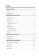
Content INTRODUCTION...................................................................... 1 Features................................................................................................................ 1 Package Contents................................................................................................. 1 HARDWARE DESCRIPTION .................................................. 3 Physical Dimensions......................................................................................
Authentication Configuration ........................................................................... 13 System IP Configuration.................................................................................. 14 System Status ................................................................................................. 15 Default Switch Setting and Reboot.................................................................. 16 Port Management .............................................................
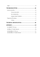
Logout................................................................................................................. 45 TROUBLESHOOTING .......................................................... 46 Incorrect connections.......................................................................................... 46 Faulty or loose cables ....................................................................... 46 Non-standard cables .........................................................................
Introduction The ES-5226RS is a multi-port Switch that can be used to build high-performance switched workgroup networks. This switch is a store-and-forward device that offers low latency for high-speed networking. The switch is targeted at workgroup, department or backbone computing environment. The ES-5226RS has 24 auto-sensing 10/100Base-TX RJ-45 ports and 2 auto-detect Gigabit combo ports for higher connection speed. This switch features a store-and-forward switching scheme.
Unpack the contents of the ES-5226RS and verify them against the checklist below: ES-5226RS Mounting Plate Power Cord Four Rubber Pads User Manual Compare the contents of the ES-5226RS package with the standard checklist above. If any item is missing or damaged, please contact the local dealer for exchanging.
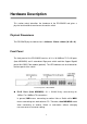
Hardware Description This section mainly describes the hardware of the ES-5226RS and gives a physical and functional overview on the certain switch. Physical Dimensions The ES-5226RS physical dimensions is 440mm x 120mm x 44mm (W x D x H). Front Panel The front panel of the ES-5226RS consists of 24 x 10/100Base-TX RJ-45 ports (Auto MDI/MDIX) and 2 auto-detect Giga ports which could be Copper Gigabit port or Mini-GBIC Fiber module (optional).
2 Giga port: The traditional RJ-45 ports can be used for up-linking wide-band paths in short distance (<100m), or the appropriate replaceable mini-GBIC ports can be used for the application of wideband up-linking and long distance transmissions to fit the flexible field request. [NOTE] When the Mini-GBIC slot and the corresponding RJ-45 port are both being connected, the Mini-GBIC (Giga fiber) port has higher priority.
LED Indicators The LED Indicators display real-time information of systematic operation status. The following table provides descriptions of LED status and their meaning.
meaning.
Desktop Installation Set the switch on a sufficiently large flat space with a power outlet nearby. The surface where the user put the switch should be clean, smooth, level and sturdy. Make sure there is enough clearance around the switch to allow attachment of cables, power cord and allow air circulation. Attaching Rubber Pads A. Make sure mounting surface on the bottom of the switch is grease and dust free. B. Remove adhesive backing from your Rubber Pads. C.
[NOTE] For proper ventilation, it allows about at least 4 inches (10 cm) of clearance on the front and 3.4 inches (8 cm) on the back of the Switch. This is especially important for enclosed rack installation. Power On Connect the power cord to the power socket on the rear panel of the Switch. The other side of power cord connects to the power outlet. The internal power supply of the Switch works with voltage in the range of 100-240VAC and Frequency of 50~60Hz.
Network Application This section provides you a few samples of network topology in which the switch is used. In general, the ES-5226RS is designed as a segment switch which with its large address table (4k MAC address) and high performance, it is ideal for interconnecting networking segments. PC, workstations, and servers can communicate each other by directly connecting with ES-5226RS.
Segment Uplink In the illustration below, two Ethernet switches (with PCs, print server, and local server attached) are connected via 1000-FX or 10/100/1000Base-TX cable. All the devices in this network can communicate with each other through the switches. Connecting servers to the switch allows other users to access the data on server.
Web-Based Management This section introduces the configuration and functions of the Web-Based management. About Web-based Management An embedded HTML web site resides in flash memory on the CPU board of the switch. It offers advanced management features and allows users to manage the switch from anywhere on the network through a standard browser such as Microsoft Internet Explorer. The Web-Based Management supports Internet Explorer 6.0.
User Login 1. Launch the Internet Explorer. 2. Key in ‘http://’ and the IP address assigned to the ES-5226RS. Then, press “Enter”. 3. The login screen appears. 4. Key in ID & Password. The default login ID and password are “1234”. 5. Click “OK”, then the main page of the Web-based management appears.
Administrator Administrator includes Authentication Configuration, System IP Configuration, System Status, and Load Default Setting. Authentication Configuration Change web management login user name and password for the management security issue. 1. Username: Type in the new user name (The default value is ‘admin’). 2. Password: Type in the new password (The default value is ‘1234’). 3. Confirm password: Re-type the new password. 4. And then, click Apply .
System IP Configuration User can configure the IP Settings and DHCP client function in here. IP Address: Manually assign the IP address that the network is using. If DHCP function is enabled, the user doesn’t need to assign the IP address. And, the network DHCP server will assign the IP address displaying in this column for the switch. The default IP is 192.168.2.1. Subnet Mask: Assign the subnet mask to the IP address.
System Status This page displays the information about the switch’s MAC address, how many ports it has, system version and kernel version. Besides, users can also fill in up to 12 characters in the Comment field for note. MAC Address: Displays the unique hardware address assigned by manufacturer (default). Number of Ports: Displays how many ports there are in the switch. Comment: Users can fill in up to 12 characters in this field. Click the Update button to save the comments.
Default Switch Setting and Reboot Reset switch to default configuration. Click Default to reset all configurations to the default value. Factory Default interface When you see the information as below, close the web window and launch again after a while.
Port Management Port Management includes Port Configuration, Port Mirroring, Bandwidth Control, and Broadcast Storm Control. Port Configuration In Port Configuration, you can set and view the operation mode for each port. Auto-Negotiation: Enable and Disable. Being set as ‘Enable’, the Speed, Duplex mode, Pause, Backpressure, TX Capability and Address Learning are negotiated automatically. When you set it as ‘Disable’, you have to assign those items manually.
Port Configuration interface 18
Port Mirroring The Port mirroring is a method for monitoring traffic in switched networks. That Traffic through ports can be monitored by any of the ports means traffic goes in or out monitored (source) ports will be duplicated into mirroring (destination) port. Port Mirroring interface Dest Port: Tick the check boxes beneath the port number label to be the destination (mirroring) port for monitoring Rx only, Tx only or both RX and TX traffic which come from the source port.
Bandwidth Control You can set up every port’s frame limitation type and bandwidth rate. Bandwidth Control interface Speed Base: Pull down the selection menu item to choose the speed base in low or high mode. As the picture shows, Port No: Pull down the selection menu to choose a port to be configured.
Tx Rate: Pull down the selection menu to choose the transmitting rate. When Speed Base is set as Low, the transmitting rate for all the ports is in the range between 32K bytes and 8M bytes. When Speed Base is set as High, the transmitting rate for port 1 ~ 24 is in the range between 256K bytes and 64M bytes; the transmitting rate for port 25 & 26 is in the range between 2M bytes and 510M bytes. Rx Rate: Pull down the selection menu to choose the receiving rate.
Broadcast Storm Control The switch implements a broadcast storm control mechanism. Tick the check boxes to have them beginning to drop incoming broadcast packets if the received broadcast packet counts reach the threshold defined. Each port’s broadcast storm protection function can be enabled individually by ticking the check boxes.
VLAN Setting A Virtual LAN (VLAN) is a logical network grouping that limits the broadcast domain, which would allow you to isolate network traffic, so only the members of the same VLAN will receive traffic from the ones of the same VLAN. Basically, creating a VLAN from a switch is logically equivalent of reconnecting a group of network devices to another Layer 2 switch. However, all the network devices are still plugged into the same switch physically.
VLAN Member Setting (Port Based) interface 24
VLAN Mode Tagged-based VLAN is an IEEE 802.1Q specification standard. Therefore, it is possible to create a VLAN across devices from different switch venders. IEEE 802.1Q VLAN uses a technique to insert a “tag” into the Ethernet frames. Tag contains a VLAN Identifier (VID) that indicates the VLAN numbers. Please notice that this page is only for Tag Based VLAN. VLAN Mode interface VLAN Mode: Displays VLAN mode.
care, and RemoveTag—for selecting. ¾ Uplink: In normal operation, if the destination and source are located in different VLANs, the packets will be dropped. Having ticked the radio button, the port is configured as an up-link port which is used in an application such as virus check or firewall. For example, the two up-link ports are located in different VLANs and are connected to a virus check station or firewall. The virus check station or firewall will check whether the packet contains the virus pattern.
VLAN PVID Index Setting The switch supports a 32-entry VLAN table to provide 32 active VLANs out of 4096 VLANs defined in IEEE802.1Q. User can define 32 VID entries in the VID table and enable the tag VLAN function. When a tagged packet is received, the switch compares the VID field in the packet with the ones defined in the VID table. If it is not matched, the switch drops the packet.
VLAN PVID Index Setting interface 28
Per Port Counter This page displays the statistics of each port. Four counter categories—Receive Packet & Transmit Packet, Collision Count & Transmit Packet, Drop Packet & Receive Packet, and CRC error Packet & Receive Packet—are available to be chosen. Receive Packet & Transmit Packet: Displays the counts of received and transmitted packets of each port. Collision Count & Transmit Packet: Displays the counts of collision occurred and the counts of transmitted packets.
Per Port Counter interface 30
QoS Setting Here you can configure QoS policy priority mode and CoS (Class of Service) configuration. QoS (Quality of Service) refers to mechanisms in the network software that make the actual determination of which packets have priority. CoS refers to feature sets, or groups of services, that are assigned to users based on company policy. If a feature set includes priority transmission, then CoS winds up being implemented in QoS functions within the routers and switches in the network.
Priority Mode There are three priority modes available to specify the priority of packets being serviced. Those include First-In-First-Out, All-High-Before-Low, and Weight-Round-Robin. First-In-First-Out: Packets are placed into the queue and serviced in the order they were received. All-High-Before-Low: The packets of low weight will be serviced after all of the packets of high weight are serviced.
Class of Service Configuration Class of Service (CoS) is a 3-bit field within a layer two Ethernet frame header using IEEE 802.1Q. Class of Service (CoS) is a way of managing traffic in a network by grouping similar types of traffic (for example, e-mail, streaming video, voice, large document file transfer) together and treating each type as a class with its own level of service priority.
Class of Service Configuration interface 34
Security Filter This function provides the security which only the MAC addresses bound with the port are allowed to access it. Port No: Displays the port number being assigned the MAC addresses. MAC Address: Users can assign up to 3 MAC addresses to the port. Read: Pull down the selection bar to choose a port number and click the Read button to show the MAC addresses bound with the port or modify the MAC addresses.
MAC Address Filter interface 36
Trunk Port trunk allows multiple links to be bundled together and act as a single physical link for increased throughput. It provides load balancing, and redundancy of links in a switched inter-network. Actually, the link does not have an inherent total bandwidth equal to the sum of its component physical links. Traffic in a trunk is distributed across an individual link within the trunk in a deterministic method that called a hash algorithm.
be aggregated together to form a logic trunk group. Trunk 0: There are four ports—port 1 to port 4—can be involved in a trunk group. Tick at least two check boxes and select the trunk type to configure Trunk 0. Trunk 1: There are four ports—port 5 to port 8—can be involved in a trunk group. Tick at least two check boxes and select the trunk type to configure Trunk 1. Trunk 2: There are two ports—port 25 and port 26—can be involved in trunk group 2.
Aggregation Information Having set up the Trunk Configuration page in static mode, you will see the static trunk group information in here.
Configuration Backup/Recovery Backup: This page allows the user to back up the system configuration by copying the text in the field below to a text file. Recovery: If the user wants to restore the previous configuration, just copies the text from the text file and pastes it to the system information field. Then the user has to fill in the password (login password) and click the Update button to start system configuration recovery process.
Firmware Update The firmware update function supports web and command prompt window interface for the user to update the firmware to the switch. Both the method require the user to type in the password (login password) and type again for password confirmation, then click Update to start firmware update process. Firmware Update interface Please note that the system will erase the flash at first. When the erase process is complete, the new firmware is to be updated.
Updating Firmware to the flash interface After a while, the message shows as below to indicate the user that the update process is complete. Update Complete message on web As for TFTP firmware update, users can get into the command prompt window to proceed. The command prompt window can be opened by entering "cmd" (without quotes) into Start-Run or through Start-All Programs-Accessories. A black and white window (the colors can be changed) containing the command prompt will open. Type in “tftp -i 192.
name of the firmware) and press enter to update. Command Prompt Window Note The system will erase the flash at first and then update the new firmware during the update process. If the update process is not finished, the web page of Firmware Update will always be displayed when the switch powers on.
Reboot Click Reboot to restart the switch.
Logout Having clicked on Logout item in the tree menu, the system will ask the user to make sure to log out by clicking the Accept button or clicking the Back button to return to the previous web page.
Troubleshooting This section is intended to help the user solve the most common problems on the ES-5226RS. Incorrect connections The switch port can auto-detect straight or crossover cable when the user links switch with other Ethernet device. The RJ-45 connector should use correct UTP or STP cable. 10/100Mbps ports use 2 pairs twisted cable and Gigabit 1000T ports use 4 pairs twisted cable. If the RJ-45 connector is not correctly pinned on right position then the link will fail.
Improper Network Topologies It is important to make sure that users have a valid network topology. Common topology faults include excessive cable length and too many repeaters (hubs) between end nodes. In addition, the user should make sure that the network topology contains no data path loops. Between any two ends nodes, there should be only one active cabling path at any time. Data path loops will cause broadcast storms that will severely impact the network performance.
Technical Specification This section provides the specifications of ES-5226RS. IEEE802.3 10BASE-T IEEE802.3u 100BASE-TX IEEE802.3ab 1000BASE-T Standard IEEE802.3z Gigabit fiber IEEE802.3x Flow control and Back pressure IEEE802.3ad Port Trunk IEEE802.
Flash ROM 512Kbytes Power Supply 100 ~ 240VAC, 50/60Hz Power Consumption 15.4Watts (Maximum) Operating Temp. 0oC ~ 45oC Operating Humidity 10% ~ 90% (Non-condensing) Storage Temp.
Appendix 10 /100BASE-TX Pin outs With10/100BASE-TX cable, pins 1 and 2 are used for transmitting data, and pins 3 and 6 for receiving data. RJ-45 Pin Assignments Pin Number Assignment 1 Tx+ 2 Tx- 3 Rx+ 6 Rx- [NOTE] “+” and “-” signs represent the polarity of the wires that make up each wire pair. The table below shows the 10 / 100BASE-TX MDI and MDI-X port pin outs.
Straight-through cable schematic Cross over cable schematic 10/100/1000Base-TX Pin outs The following figure shows the 10/100/1000 Ethernet RJ-45 pin outs.
10/100/1000Base-TX Cable Schematic Straight through cables schematic Cross over cables schematic 52
53