PT-31E/PT-31W User Manual 11-2012 / v1.
COPYRIGHT Copyright Edimax Technology Co., Ltd. all rights reserved. No part of this publication may be reproduced, transmitted, transcribed, stored in a retrieval system, or translated into any language or computer language, in any form or by any means, electronic, mechanical, magnetic, optical, chemical, manual or otherwise, without the prior written permission from Edimax Technology Co., Ltd. Edimax Technology Co., Ltd.
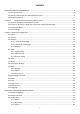
CONTENTS CHAPTER I: PRODUCT INFORMATION ............................................................................................................... 4 1-1 Package Contents ................................................................................................................................ 4 1-2 Getting Familiar with Your New Network Camera .............................................................................. 4 1-3 Camera Installation ...................................................
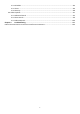
-3-4 Schedule ................................................................................................................................. 84 4-3-5 Event ....................................................................................................................................... 86 4-3-6 Security ................................................................................................................................... 88 4-4 Video Playback ............................................
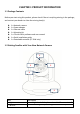
CHAPTER I: PRODUCT INFORMATION 1-1 Package Contents Before you start using this product, please check if there is anything missing in the package, and contact your dealer to claim the missing item(s): 1 x Network camera 1 x Power adapter 1 x Ethernet cable 1 x Mounting kit 1 x CD with utility software and user manual 1 x Quick installation guide 1 x Detachable antenna (PT-31W only) 1-2 Getting Familiar with Your New Network Camera 1 3 2 \2 \2 4 \2 5 \2 Item 1 - Light sensor 2 - IR LE
If the image looks fuzzy, try to turn this focus ring clockwise or counter-clockwise to adjust focus until the image looks clear Receives voice There are 2 LED lights inside to indicate the operation of this IP camera: 3 - Focus ring 4 - Microphone 5 - LED indicators Left: Network activity LED On: Ethernet cable connected Off: Ethernet cable disconnected Flash: Transferring data Right: Power LED On: IP camera is switched on Off: IP camera is switched off Please note: These LEDs can be switched off regardl
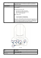
3 - RESET 4 - DI/DO connectors 5 - ETHERNET 6 – SD card slot When the IP camera is not functioning properly, you can use a pen or similar object to press this reset button to reset the IP camera. You can also press and hold this button for more than 5 seconds to clear all settings of IP camera, include administrator password. For external sensor and alarm. WARNING: DO NOT CONNECT POWERED CABLE! Connect to your local area network by Ethernet cable. Inserts SD card for video recording.
second. IP camera will connect AP and set value during 5 ~10 seconds. 4 - DI/DO Digital input / output dry contacts. Connects to external connectors peripherals by wire. See next page for pin definitions. WARNING: DO NOT CONNECT POWERED CABLE! 5 – ETHERNET Connect to your local area network by Ethernet cable. 6 - SD card slot Inserts SD card for video recording. Maximum 32GB** of SDHD card supported. 7 – Connector for Connect the detachable antenna when wireless connection is detachable required.
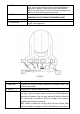
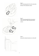
Step 2: Insert mounting plate B into the slot at the bottom of the network camera. Step 3: Screw mounting plate B to the network camera via the 2 holes indicated by the arrows. Step 4: Mount the network camera on to the wall.
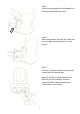
Step 5: Screw mounting plate A and B together via the hole indicated by the arrow. Step 6: When mounted on the wall, the cables can pass through mounting plate A as in the picture. Step 7: Connect an Ethernet cable to the network camera via the Ethernet port. Note: PT-31E (PoE model) supports the IEEE 802.3af PoE standard. It can be powered via the Ethernet cable when connected to a PoE switch.
Step 8: Insert the DI/DO signal cable(s) into the DI/DO port. If you do not have DI/DO accessories, you can skip this step. Step 9: Connect the power adapter to the network camera, then plug the power adapter into a wall socket. The camera’s LED lights should light up after a few seconds, and the camera will test its pan and tilt motor within 1 minute. Please do not obstruct the network camera while it is testing its pan and tilt motor.
Chapter II Using Network IP Camera by Web Interface 2.1 Locate the IP address of Network IP Camera You can use your new Network IP Camera by its web user interface via web browser. Currently the viewing system requirement for Network IP camera is: ■ OS: Microsoft Windows XP/Vista/7 ■ Browser: IE7, 8, 9 ■ Cell phone: 3GPP player Note: For best viewing experience we recommend that you use Microsoft Windows Internet Explorer 7, 8, or 9 .
Note: The contents of the CD-ROM can also be downloaded from the Edimax website: http://www.edimax.com/en/index.php 2. After the installation is complete, double-click the “EdiView_Finder” icon to execute the application. 3. Press ‘Discover’ button to search for all IP Cameras on your local network (make sure all IP Cameras are powered on and connect to local network first). When you find any IP Camera, you can double click on it or click ‘Link’ button to connect to it by your web browser.
2.2 Connect to IP Camera’s Web User Interface and Install ActiveX Plugin When you know the IP address of IP Camera, you can connect to it by Internet Explorer web browser by entering its IP address in address bar. The use login screen will appear when you get connected: IP Camera’s administrator username is ‘admin’ (lower case) and password is ‘1234’ by default. Click ‘OK’ button or press ‘ENTER’ key on your keyboard when you finish entering username and password.
For IE 9: Click ‘Install’ button located at the bottom of IE to install ActiveX plugin. If you’re prompted that: ‘Windows Firewall has blocked some features of this program’ Click ‘Allow access’, or IP Camera will not be able to function properly. When you’re installing Internet Explorer plugin, you may also be prompted that if you want to allow changes to be made to your computer: Click ‘Yes’ to allow changes.
After ActiveX plugin is installed, you should be able to see the video stream from camera. NOTE: If this is the first time you use this IP Camera, you can refer to chapter 2.4 for instructions on Setup Wizard, which will guide you to complete the software setup of your new IP Camera. 2.3 Viewing Live Video After ActiveX control is installed, you can view IP camera’s video by web browser.
There are various controls on web page, here are descriptions of every control item: Item Description ‘Home’ button This button is visible in all setup pages of IP camera, and you can go back to live video view by clicking this button when you’re in other page. Stream Select video stream type: H.264 or MJPEG. H.264 required less network bandwidth and this will help when network connection is slow. Digital Output Switch digital output interface on or off.
Click ‘Save’ button when you see the image you wish to save, and you’ll be prompted to indicate the folder on your computer to save image file. If you changed your mind and don’t want to save image file, click ‘Cancel’. ‘Start Video Record’ button Click this button to record video and save video file on your computer. You’ll be prompted to indicate the folder on your computer to save video file.
2.4 Client Settings In ‘Client Settings’ menu, you configure basic IP camera settings like data transfer protocol and data storage folder. To access ‘Client Settings’ menu, click ‘Client Settings’ button on the left.
Here are the descriptions of every setup item: Item Description RTSP Select this option to use RTSP (Real-Time Streaming Protocol) to transfer video data. HTTP Select this option to use HTTP (Hyper-Text Transfer Protocol) to transfer video data. If you don’t know which one you should use, select ‘RTSP’. Folder Prefix Add date and time suffix to file name Select a folder on your computer to save recorded video. Click ‘Browse’ button and you’ll be prompted to select a folder.
Chapter III Advanced Configuration If you wish to configure IP camera’s settings, you can access IP camera’s ‘Configuration’ menu, which provides various kinds of system setting. To access configuration menu, click ‘Configuration’ button on the left. The ‘Configuration’ submenu will appear, please pick a setup item you wish to configure. 3-1 System In this menu, you can configure basic IP camera settings like hostname and time.
Here are the descriptions of every setup item: Item Description Host Name Input the IP camera’s hostname here, it can be any meaningful words or characters that will help you to identify this IP camera. You can use IP camera’s installation location as host name, and this will help you to identify IP camera when you have many IP cameras installed. Indicator LED The LED lights located at the back of IP camera is switched on by default.
Set Manually Please note that if this IP camera can’t access Internet, you must have a time server on local area network, or set the time manually. Set IP camera’s date and time manually. Please set current date and time by ‘Date’ and ‘Time’ dropdown menu. When you finish with above settings, click ‘Apply’ button to save changes. 3-2 Security In this menu, you can configure IP camera’s login account.
Here are the descriptions of every setup item: Item Description Password / Retype Input administrator’s new password in both ‘Password’ and ‘Retype Password Password’ field, and click ‘Modify’ button to change administrator’s (Administrator) password. Please note: Don’t forget administrator’s password! Or you’ll need to reset IP camera’s all settings to get administrator’s password recovered. Account List Here lists all users existed in IP camera.
3-3 Network You can configure the network camera’s general and advanced network settings here. 3-3-1 “General” Setup Page Set up IP address for this IP camera. This IP camera supports both IPv4 and IPv6 IP address. Here are the descriptions of every setup item: Item Description LAN Select this option to assign an IP address to LAN port (or obtain an address from DHCP server automatically).
Available options are: DHCP IPv4: Obtain an IPv4 IP address from DHCP server on LAN automatically. DHCP IPv4 / IPv6: Obtain both IPv4 and IPv6 address from DHCP server on LAN automatically. Static IPv4 / IPv6: Assign an IPv4 / IPv6 address to IP camera manually. If you don’t have a DHCP server on your local area network, you must use this option to specify an IP address.
RTSP Port RTP Data Port camera’s web configuration interface. Input RTSP port number. When this port number changes, you must change corresponding settings in external network devices (NVR or CMS software) so they can receive this IP camera’s video. Input RTP data port number here. When you finish with above settings, click ‘Apply’ button to save changes. 3-3-2 “Advanced” Setup Page You can setup advanced network settings in this page.
Here are the descriptions of every setup item: Item Description Multicast Enable video multicast: Multicast Group Address: Input multicast group address here, must be an address between 232.0.0.0 to 232.255.255.255. Multicast video port: Input port number for video multicast here. Multicast RCTP video port: Input port number for RCTP video here. Multicast audio port: Input port number for audio here. Multicast RCTP audio port: Input port number for RCTP audio here.
you. You must register a dynamic IP service first. Currently this IP camera supports Dyndns, TZO and No-ip dynamic IP service.. Provider: Select dynamic IP service provider. Host Name: Input the host name you obtained from dynamic IP service provider. User name: Input user name used to login dynamic IP service provider. HTTPS Password: Input the password used to login dynamic IP service provider. *The user name and password should be under 16 characters.
The descriptions of every setting in this menu will be given below: Item Description Wireless Select „Enable‟ to activate wireless network function of this IP camera, Connection select „Disable‟ to disable it. Network Type Select the network type of wireless connection.
SSID Channel Authentication Pin Code Input the SSID of the wireless access point you wish to connect. It should be less than 32 alphanumerical characters. When you select a wireless access point above, it‟s SSID will be filled in this field automatically. However, if the SSID is not displayed (the wireless access point you selected choose to hide it‟s SSID), you have to know it‟s SSID and input it here, or you will not be able to connect it. Select the radio channel you wish to use here.
Configure via Push Button Configure via PinCode connection. Click this button and this camera will enter PBC-style WPS connection state for 120 seconds. Please push „Start PBC‟ button on the wireless access point you wish to connect within 120 seconds to establish WPS connection (The remaining time will be displayed on the button). If connection can not be established after 120 seconds, you‟ll be prompted by a message box, and you can press „Start PBC‟ button to try again.
Method 2: USE PINCODE SETTING Step 1: Power on the wireless AP and the wireless network camera. Wait for 1 minute for both devices to be up and running. Step 2: Open web browser and logo in wireless server. Go to wireless/WPS setting page. Step 3: Open web browser and logo in wireless network camera. Go to network/Wireless setting page. And find Wi-Fi Protected Setup (WPS) item. Step 4: Please find the pin Code on both setting page and key in it in each “Configure via Pin Code”.
3-4 IP Filter When this IP camera is directly connected to Internet and not protected by firewall, this function acts like a mini built-in firewall to protect the safety of this IP camera and avoid attacks from hackers. Here are the descriptions of every setup item: Item Description Enable Filter Check this box to enable IP address filter, uncheck this Box to disable this function. Accepted IP list Here lists all IP address that can build connections to this IP camera.
camera. If you want to remove a set of IP address from the list, click on the IP address and click ‘Remove’ button. IP Address Input the starting and ending IP address of IP address you wish to (Accepted IP list) deny connections here. IP camera will deny connections established from these IP address. If you want to specify one IP address only, input the same IP address in both field. Click ‘New’ button to add IP address into deny IP list.
3-5 Video You can adjust the image of the IP camera in this menu. There are 3 sub-menus in this menu: Image Setting, Video Setting, and Overlay, which can be accessed by tabs on the top: 3-5-1 Image Setting You can adjust the image parameters in this page. Here are the descriptions of every setup item: Item Brightness / Contrast / Saturation / Description Control the image parameters. Click ‘ - ' to decrease value, or click ‘ + ‘ to increase value. You can also input the value in the field directly.
Shaprness Default Mirror Power Line Frequency Set all above values to default value ‘128’. Check ‘Vertical’ or ‘Horizontal’ box to flip the image vertically or horizontally, this will help to correct the orientation of image when IP camera is hanged bottom-up by camera holder. You can click both ‘Vertical’ and ‘Horizontal’ box at the same time. Select the frequency of power line of the place you’re using this IP camera. This will help to reduce the flicker of certain lights in the image.
Here are the descriptions of every setup item: Item Description H.264 Select the compression of main stream: H.264 / MPEG4. /MPEG4 Video Select video resolution. Resolution - H.
3-5-3 Overlay Setting You can adjust the video overlay parameters in this page. Here are the descriptions of every setup item: Item Description Enable Time Check this box to enable overlaying time stamp on video. Stamp Remove the Check this box to remove time stamp’s background color. You may background color find this will help the readability of time stamp text in some cases.
‘Update’ button to use the picture. Please note that there are certain restrictions: - Select .bmp / .jpg / .jpeg image files only. - Image’s resolution should be less than 160 x 128, and can be divided by 4. - Do not upload image files that size is greater than 64KB. When you finish with above settings, click ‘Apply’ button to save changes. 3-6 Audio You can adjust audio input / output parameters here.
Enable Speaker Check this box to enable speaker. If you don’t want people at IP camera (Speaker) to hear you, you can uncheck this box to disable it. Audio Type The format is fixed as G.711 (Speaker) When you finish with above settings, click ‘Apply’ button to save changes. 3-7 Motion This IP camera is capable to detect object’s motion, so IP camera will only record when there’s motion and save disk storage space.
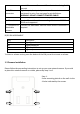
Enable (Window 1 to Window 3) Check this box to enable this motion detection window. You can select window 1 to 3 to enable up to 3 motion detection windows. When a motion detection window is enabled, a rectangular will appear on camera’s view, with its title on the top. - To move / resize a motion detection window: - Move: Use the mouse to drag the title text. - Resize: Use the mouse the drag the four corners (upper-left/right, lower-left/right) to resize it.
Here are the descriptions of every setup item: Item Description Enable RS-485 Check this box to enable RS-485 functionality. Use Pelco-D Select this option and RS-485 interface will output pan-tile control signal in Pelco-D format. This format is widely accepted by most of pan-tilt camera cradles. Use Custom Protocol You have also input pan-tilt camera cradle’s address code in ‘Address’ field (number must be between 0~255). This code must be identical to pan-tilt camera cradle’s address code.
- Stop Bit: Select stop bit: 1 or 2. - Home/Up/Down/Left/Right: Input the command string used to move pan-tilt camera cradle to home or up/down/left/right position. You can click ‘Test’ button to send command string for testing. - Command 1 ~ 5: You can define extra pan-tilt camera cradle control strings here by giving it a name (Command Name) and command string (Hexadecimal Message). You can also click ‘Test’ button to send command string for testing.
3-9-1 Settings This page lists all existing events. You can click ‘Modify’ button to edit an existing event, or ‘Remove’ to delete an existing event. To create a new even, just click “New” button to add an Event setting.
Item Enable Setting Title Motion Detection Digital Input 1~2 Enable Schedule Time Enable FTP Enable EMAIL Enable Samba (Net Storage) Enable SD CARD Trigger digital output for xx second(s). Description Check this box to enable this event. If you just want to disable this event temporarily, you can uncheck this box to keep this event and disabling while not deleting it. Input any description text for this event so you can identify it quickly. You can use alphabets, numbers, and symbols include: !$-.
3-9-2 Media You can define what kind of media file should be saved on designated media. Here are the descriptions of every setup item: Item Description One Snapshot Save a picture file when event is triggered. H.264 Video Save a H.264 video clip. You can also select the recording length before and / or after the time when event is triggered in ‘Pre Event’ and ‘Post’ Event’.
3-9-3 Event Server You can define the details of remote media server: FTP (File), SMTP (Email), and Samba (File). A Samba server can be any computer running windows operating system with network neighbor function enabled. Many stand-alone network file server also support samba server function. Here are the descriptions of every setup item: Item Description FTP Server Check this box to enable FTP server upload. - FTP Server: Input FTP server’s IP address or hostname. - Port: Input FTP server’s port number.
SMTP Server on FTP server, like ‘upload/record’. If you want to save file on this FTP user’s home directory, you can leave this field blank. - Enable Passive Mode: Check this box to force IP camera to communicate with FTP server in passive mode (Some FTP Server may only work when you check this box, while others don’t). - Test FTP: Click this button to test FTP server settings above immediately. Check this box to enable Email send. - SMTP Server: Input SMTP server’s IP address or hostname.
Samba Server input Email server’s username and password in corresponding field. - Requires SSL Encryption: If your Email server required SSL encryption, check this box. Please note that some Email server uses different port number than standard port 25 when SSL encryption is used. - STARTTLS: If your Email server required STARTTLS encryption, check this box. Please note that some Email server uses different port number than standard port 25 when STARTTLS encryption is used.
3-10 Recording to SD Card When a SD card is inserted into IP camera, you can save video files on it. Note: 1. Be sure that the SD Card format should be FAT32. The NTFS format cannot be supported by this camera. 2. Unlink motion detection, this function will record video at specified time period on selected weekday(s). Here are the descriptions of every setup item: Item Description Enable External Check this box to record video on SD card.
3-11 SDHC The IP camera module has an optional SD card slot PCBA board. The standard module does not include this board. The UI shows the capacity is 0 MB when the module without SD card slot and memory card. f you need the function please check the option when you place the order of the IP camera module. Once the module equipped SD card slot and SD card is inserted, the UI will show the capacity of the SD card like the image hereunder. There are two UI pages to show the record on the SD card.
Set the time range then click “Search” then shows the records like below.
3-12 Log You can check the usage log of IP camera here. In this page, you can click: 1. First page / Final page: Jump to first / final page of log. 2. Previous / Next: Jump to previous or next page of log. 3. Remove: Clear log. You’ll be prompted for confirmation.
3-13 Device Info You can check the information and network settings of this IP camera. These information are very useful when you need to repair or fix the problem of this IP camera.
3-14 Maintenance You can do some maintenance job about this IP camera here. Here are the descriptions of every setup item: Item Description Reboot Click this button to reboot the IP camera. This function is useful when you find IP camera is not working properly. Reset Clear all settings of IP camera and reset to factory default setting. Backup Backup IP camera’s setting and save it on your computer. Backup to Backup IP camera’s setting and save it on Micro SD Micro SD card card.
Upgrade Upgrade IP camera’s firmware. Click ‘Browse’ button to select a firmware image file on your computer first, then click ‘Upgrade’ button. 3-15 Language You can change the display language of web interface. Click ‘Language’ button and select one language. More languages may available in latest firmware file.
CHAPTER IV: EDIVIEW 64-CHANNEL VIEWER 4-1 EdiView Installation Please follow the following instructions to setup EdiView on Windows Vista / 7 operating system. Please note: You must login as system administrator when you’re installing EdiView . 1. Locate EdiView setup file, and double-click on it to start EdiView software installation.
2. You’ll see a User Account Control security warning message appear, click ‘Yes’ to continue. 3. Click ‘Next’ to continue. 4. Click ‘Install’ to begin installation.
5. ase wait while installation is being performed. This may take few minutes to done, please be patient.
6. The second part of installation will start automatically. 7. A new setup window will appear, please click ‘Next’ button to continue. 8. You can select a folder on your computer to install EdiView by clicking ‘Change’ button, or simply click ‘Next’ button directly to accept default folder.
9. Click ‘Install’ to continue. 10.Installation will take few minutes, please be patient.
11.Click ‘Finish’ when you see this message. EdiView is ready to use now. 12.MSDE (Microsoft SQL Database Engine) installation procedure will start at the same time. Please wait until it completes.
13.You’ll be prompted that this program has compatibility issues, click ‘Run program’ to continue.
14.MSDE installation requires computer reboot to complete, click ‘Finish’ to reboot the computer. 15.A new icon will appear on your computer’s desktop, you can double click on it to start EdiView.
65
You’ll see a User Account Control security warning message appear, click ‘Yes’ to continue. EdiView login window will appear. Default user ID is ‘admin’ and default password is ‘1234’, click ‘OK’ when ready.
The main window of EdiView will appear: Date/Time, Remaining disk space Exit Snapshot camera selection Camera View Function Keys Split-screen mode selector 67
The descriptions of every item are listed as follow: Item Split-screen mode selector Full-screen Camera Scan Snapshot EMAP Description EdiView supports from 1 to 64 cameras split views. The video from IP camera will display in split-screen display cells, and you can view up to 64 IP cameras at the same time. Click the button to select the number of IP cameras you wish to view on display.
Select the file, and click ‘Open’ button to use the picture as background picture.
‘Motion Detected’ if you want to get a warning message when image lost of motion is detected, then select the direction of camera icon, this will help you to remember the orientation of camera on the EMAP. After you click ‘OK’ button, a camera icon will appear on EMAP with its camera number indicated: Configuration You can add more cameras to EMAP by repeating procedures listed above. Enter EdiView configuration page. See next chapter for detailed instructions. Playback Playback recorded video.
Date / Time, Remaining Disk Space Exit Displays current date, time, and remaining disk storage space.
The description of these items is listed as follow: Item Pan / Tilt control Description Click the direction arrow to control camera’s pan / tilt. Pan / Tilt speed Drag the slide bar to adjust the pan / tilt speed when you click pan / tilt control arrow. Zoom Optical zoom control. Click + or - to control zoom level. Exposure Exposure control. Click + or - to control exposure level. Cruise control Click ‘Go’ button to start camera cruise and click ‘Stop’ button to stop cruise.
The configuration menu will appear. There are 6 sub menus in the configuration menu: Device (Add or remove IP camera / video server) Recording (Configure video recording) System (Configure system-wide settings) Schedule (Configure schedule recording) Event (Configure event recording) Security (Configure EdiView user list) Detailed descriptions of every sub menu will be given in following chapters.
74
IP camera setup window will appear on the right: If your IP camera is located on local area network, click ‘Search’ button. Wait for few seconds or few minutes until the search is complete, and all IP cameras found on your local area network will be listed: In this example, an IP camera has been found at IP address 192.168.2.3. If this is the IP camera you wish to add, click ‘Add to list’ button. You can repeat above procedures to add all IP cameras you wish to connect.
When an IP camera is found, you can also select it in the list and: View Image: View the live image from selected IP camera. Detail: Connect to selected IP camera’s web configuration menu. You can also select the video stream type you wish to use: Check ‘Enable Camera’ to enable this camera is EdiView. If the IP camera you wish to add is not located on local area network, you have to input the details of IP camera manually: 1.
Every IP camera has a check box, indicating if it is enabled. If a camera is not enabled, it will not be displayed in EdiView’s video view. You can also manage IP camera list by the following function: Enable All: Enable all IP cameras in the list. Disable All: Disable all IP cameras in the list. Remove: Remove selected IP camera. When you selected an IP camera in the list, you can also click ‘Update to list’ button to update its information, like IP address and user name / password.
The descriptions of every item are listed as follow: Item Select Camera Record Mode Description All IP camera’s Please select an IP camera from the list to setup its recording behavior. EdiView will attempt to connect to selected IP camera, if it’s not connectable, you’ll receive an error message later. You can decide the recording behavior for this IP camera: Monitor only, not record: EdiView will not record video of this IP camera.
Use the mouse to click blocks on the grid pattern to assign the areas you wishes EdiView to detect / ignore motion. EdiView will detect motion for areas which are NOT covered by blocks only. To add or erase blocks: To add blocks, click + button; to erase blocks, clickbutton. Click ‘Reset’ button to reset motion detection blocks to default setting.
Drag the slide bar to setup sensitivity level from 1 to 10. Larger number indicates more sensitivity. To apply this motion detection settings to all IP cameras, click ‘Apply to All Cameras’ button. When you finish setting, click ‘OK’ button to save changes you made, or click ‘Cancel’ button to discard all settings you made. 4-3-3 System You can configure system-wide configurations in this sub menu.
No: Do not display caption on camera view Camera ID: Display Camera’s ID number Data Storage Setting Camera ID + Camera Name: Display both camera’s ID and camera’s name. Setup hard disk data storage: Enable Recycle: Check this box and the latest recording video will overwrite oldest recorded video file automatically. If you didn’t check this box, EdiView will stop recording when data storage space is full.
Start-up Condition you specified here, you’ll receive an alarm message to notify you should do something to prevent from running out of storage space. Select the behavior of EdiView when computer starts up. You can select multiple options you want to use: Auto run, when Windows start: Check this box and EdiView will run automatically when computer starts. Start program in minimum: Start EdiView as minimized window. Auto record: Start video recording automatically when EdiView starts.
same domain name. Receiver: Input the E-mail receiver’s address here. CC: input additional E-mail receiver’s address here. Subject: Input the subject of sent E-mail. This will also help you to identify the E-mail sent by EdiView . Number of attachments: Input the number of snapshot attachments that will sent with E-mail, so you can see the image of camera by E-mail (1 to 10 attachments only). Email alerts Interval: Input the time interval between two E-mails.
4-3-4 Schedule You can configure recording schedule in this sub-menu.
A new window will appear on the right: You can configure a new schedule recording job here. The descriptions of every setup items are listed as follow: Item Weekly Schedule Description Select the time period in a week of this schedule. There are total 48 x 7 blocks in a week schedule, where every block represents half an hour. You can use mouse to click on the block to add or delete time period. If recording is activated in that time period, the block will appear as light blue .
Events ‘DEL’ first, then click the time period block. Select the event to trigger recording: Round-The-Clock: Recording is time-activated (according to schedule). Motion Detection: Recording is motion-activated. Dedicated Schedule DI Input: Recording is activated by DI (Digital Input) signal located on IP camera. IP camera must have DI port and not every IP camera is equipped with DI.
EdiView can send you an alarm E-Mail message so you can know something happened on the IP camera (motion detected, video lost, or connection lost). A sound can be played to notify the operator at the computer where EdiView is installed, too. To add a new event, click ‘Add’ button, and a new window will appear on the right for you to setup a new event. To remove an existing event, select an event in the list and click ‘Remove’ button.
Trigger Operation(s) you want to specify more than one alarm condition for the same IP camera, Define the action which will be taken when alarm is triggered: Send E-Mail: an E-mail will be sent when alarm is triggered. Play Sound: Play a sound on the computer where EdiView is installed. To add a new sound file, copy the .wav file to the following directory: C:\Program Files\EdiView\media Alarm Remark Alarm Recycle You can click ‘Play’ button to play the sound file you selected.
There are two kinds of user in EdiView: Administrator and user. Administrator can configure EdiView, while user can only view video of camera, and perform limited system configuration (schedule, record, and video playback).
Administrator’s user ID is always be ‘admin’ and cannot be changed. You can only change admin’s password in Administrator’s ‘Password’ and ‘Confirm Password’ field. Please input the same password in both fields for confirmation.
The descriptions of every setup items are listed as follow: Item User ID Description Password / Confirm Password User Privilege Description Input the user ID used to login EdiView Input any descriptive text to help you to memorize the purpose of this user ID. Input this user’s password in both fields. Defines the privilege of this user (Check the boxes that you wish to give privilege): Multi-Camera View Operation: Allows multi-camera view. Camera Map Operation: Allows to show E-MAP.
A new window will appear: To play a recorded video, you can use one of following two functions: Advanced Search Event Search Please refer to following chapters for detailed instructions of every search mode.
4-4-1 Advanced Search You can search for recorded video within specific time period, and get a list of record modes of all IP cameras. When you enter this menu, please specify start time and stop time: Hour in a day DATE (You can input 0 - 23 in ‘Hour in a day’ field by keyboard directly).
When you finish, click ‘SEARCH’ button to search for recorded video, and you’ll get a similar output like this: In this picture, a recorded video of ‘Camera 1’ has been found at 12 o’clock. A blue mark indicates it’s a ‘Round Clock’ (manual) recording. Other record type include: Blue: Manual Recording Green: Recording is triggered by motion Red: Recording is triggered by Digital Input To view the video, check the box of camera ID, then click play button.
And the video will be prepared for playback.
4-4-2 Event Search You can search for video for playback by triggering event: round the clock, motion detection, or digital input.
To search for video, you have to specify: 1) starting and ending time for video searching in ‘Start time’ and ‘Stop time’ field 2) Recording mode: Round Clock, Motion Detection, and I/O Mode (Digital Input). You can check all boxes you wish to search for. 3) Camera: You can check all cameras you wish to search for video. To select camera ID more than 16, click right or left button to select camera ID up to 64, or click ‘Select All’ to select all cameras.
When you finish, click ‘Search’ button to search for recorded video, and a list similar to this will appear: You can select the video clip you wish to play, and click ‘Play’ button.
99
4-4-3 Video Playback When a video is loaded, the video playback screen will look like this: Close Time Window s Search / Capture Speed Control Video Position Video Playback Control Indicator The descriptions of every item are listed as follow: Item Close Window Video Playback Control Description Click X mark to close video playback window.
Pause a playing video, click ‘Play’ to resume video playback Skip to next video frame Skip to the ending position of video clip Speed Control Search / Capture When video is stopped, you can click + or – button to adjust video playback speed: from 1/4 to 4x speed. You cannot adjust video playback speed when video is playing. Click or button to search for video (see chapter 3-2 / 3-3 for detailed instruction). Click button to take a snapshot picture of current video playback position.
You can click ‘Save as’ button to save current image (you’ll be prompted for image saving location), or click ‘Print’ to print current image to printer. Time To back to previous menu, click ‘Cancel’; click ‘Reset’ to reset image parameters back to default value. Current time will be displayed here. You can click ‘ button to display video zoom in, or click button to display video zoom out.
Chapter V Troubleshooting Please don’t panic when you found this IP Camera is not working properly. Before you send this IP Camera back to us, you can do some simple checks to save your time: Problem Possible solution(s) description Can’t 1) Please check the IP address of IP Camera again. connect to 2) Please make sure the network cable is correctly IP Camera connected to your local area network. 3) Please make sure power cable is correctly connected to IP Camera.
Federal Communication Commission Interference Statement This equipment has been tested and found to comply with the limits for a Class B digital device, pursuant to Part 15 of FCC Rules. These limits are designed to provide reasonable protection against harmful interference in a residential installation. This equipment generates, uses, and can radiate radio frequency energy and, if not installed and used in accordance with the instructions, may cause harmful interference to radio communications.
EU Declaration of Conformity English: French: Czechian: Polish: Romanian: Russian: Magyar: Türkçe: Ukrainian: Slovakian: German: Spanish: Italian: Dutch: Portugese: Norwegian: Swedish: Danish: Finnish: This equipment is in compliance with the essential requirements and other relevant provisions of Directive 2004/108/EC, 2006/95/EC. Cet équipement est conforme aux exigences essentielles et autres dispositions de la directive 2004/108/EC, 2006/95/EC.
Declaration of Conformity We, Edimax Technology Co., Ltd., declare under our sole responsibility, that the equipment described below complies with the requirements of the European directive 2004/108/EC and 2006/95/EC. Equipment: 3Mpx PoE Day & Night PT Network Camera Model No.: PT-31E Report No.
Declaration of Conformity We, Edimax Technology Co., Ltd., declare under our sole responsibility, that the equipment described below complies with the requirements of the European R&TTE directive and EMC directive, ETSI. Equipment: 3Mpx Wireless Day & Night PT Network Camera Model No.: PT-31W Report No.: T110919202-RE1 The following European standards for essential requirements have been followed: ETSI EN 301 489-17 V2.1.1 2009-05 ETSI EN 301 489-1 V1.8.
This product includes software that is subject to the GNU General Public License version 2. The program is free software and distributed without any warranty of the author. We offer, valid for at least three years, to give you, for a charge no more than the costs of physically performing source distribution, a complete machine-readable copy of the corresponding source code. Das Produkt beinhaltet Software, die den Bedingungen der GNU/GPL-Version 2 unterliegt. Das Programm ist eine sog.
2. You may modify your copy or copies of the Program or any portion of it, thus forming a work based on the Program, and copy and distribute such modifications or work under the terms of Section 1 above, provided that you also meet all of these conditions: a) You must cause the modified files to carry prominent notices stating that you changed the files and the date of any change.
License, they do not excuse you from the conditions of this License. If you cannot distribute so as to satisfy simultaneously your obligations under this License and any other pertinent obligations, then as a consequence you may not distribute the Program at all.
111