AR-7186WnA / AR-7186WnB User Manual 1-2013 / v1.
COPYRIGHT Copyright Edimax Technology Co., Ltd. all rights reserved. No part of this publication may be reproduced, transmitted, transcribed, stored in a retrieval system, or translated into any language or computer language, in any form or by any means, electronic, mechanical, magnetic, optical, chemical, manual or otherwise, without the prior written permission from Edimax Technology Co., Ltd. Edimax Technology Co., Ltd.
Contents 1. PRODUCT INTRODUCTION ..................................................................................................................... 5 1.1. 1.2. 1.3. 1.4. 1.5. PACKAGE CONTENTS............................................................................................................................ 5 SYSTEM REQUIREMENTS ....................................................................................................................... 5 SAFETY PRECAUTIONS .............................
5.4.3. Wireless................................................................................................................................ 61 5.5. ADVANCED SETUP ............................................................................................................................. 64 5.5.1. Firewall................................................................................................................................. 64 5.5.2. Routing .....................................................
1. Product Introduction 1.1. Package Contents Before you start using this product, please check if there is anything missing in the package and contact your dealer to claim the missing item(s): ADSL2+ router (AR-7186WnA or AR-7186WnB) 12V power adapter 1 meter RJ-45 Ethernet cable 1.8M RJ-11 telephone line x 2 Quick installation guide CD containing setup wizard, user manual & multi-language QIG Splitter 5dBi antenna 1.2. System Requirements Recommended system requirements are as follows.
Do not put this device close to heat sources or high temperatures. Keep the device out of direct sunshine. Do not put this device close to a place where it is damp or wet. Do not spill any fluid on this device. Do not connect this device to any PCs or electronic products, other than those which you are instructed or recommended to do so in the product’s documentation, by our customer engineers or by your broadband provider – connecting to incorrect devices may cause a fire risk.
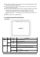
Internet Green On Flashing LAN1–4 Device in bridged mode. Red On Internet not connected in router mode (Please refer to Note ii. below). Green On LAN port connected. Green Green LAN port not connected. On Successful WLAN connection. ii. WLAN activity (transferring/receiving data). Off WLAN connection failed. Off WPS is disabled. Flashing Note i. LAN activity (transferring/receiving data). Off Flashing WPS Internet activity (transferring/receiving data) in router mode.
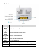
Rear Panel Item Power On/Off Button Power Wireless On/Off Button WPS Button LAN 1–4 Reset Button Line Description Switches the router on or off. Power port for included 12V power adapter. Switch the wireless signal on or off. Activate WPS (Wi-Fi Protected Setup) RJ-45 Ethernet ports 1–4. Hold for less than 5 seconds to restart the device, and hold for more than 10 seconds to reset the device to factory default settings. RJ-11 port for standard telephone line.
1.5.
2. Hardware Installation 1. Connect the ADSL line. Connect the line port of the router of the device to the modem interface of a splitter using a telephone cable. Connect a telephone to the Phone interface of the splitter using a telephone cable. Connect the Line interface of the splitter to your existing, incoming line. The splitter has three interfaces: Line: Connect to a wall phone jack (RJ-11 jack). Modem: Connect to the ADSL jack of the device. Phone: Connect to a telephone set. 2.
3. Connect the power adapter to the router. Plug one end of the power adapter into a wall outlet and connect the other end to the 12V interface of the device. The following diagrams show how to correctly connect the router, PC, splitter and the telephone sets under two different configurations: Configuration 1 0 shows the correct connection of the router, PC, splitter and the telephone sets, with no telephone set placed before the splitter.
Configuration 2 0 shows the correct connection when a telephone set is installed before the splitter. Figure 2 - Connection diagram (Connecting a telephone set before the splitter) Note: When Configuration 2 is used, the filter must be installed close to the telephone cable. Do not use the splitter to replace the filter. Installing a telephone directly before the splitter may lead to failure of connection between the device and the central office, or failure of Internet access, or slow connection speed.
5. Firewall settings. Please turn off all personal firewalls before you continue the setup – firewalls can block communication between your PC and router. Note: You must use the power adapter included in the package with the router, do NOT attempt to use a third-party power adapter. 6. PC LAN IP configuration. Configure your PC’s LAN settings to automatically obtain an IP address from the router by following the steps below: 1. Click “Start” and then select “Control Panel”. 2.
3. Locate the “Network Connections” icon and double-click to open network connection settings. 4. Select the “Local Area Connection” icon and right-click it to open the sub-menu, then select “Properties”.
5. Select “Internet Protocol (TCP/IP)” and then click “Properties” 6. Ensure that “Obtain an IP address automatically” and “Obtain DNS server address automatically” are selected and then press “OK”.
3. IP Address Setting To use the router to access the Internet, the PCs in the network must have an Ethernet adapter installed and be connected to the router either directly or through a hub or switch. The TCP/IP protocol of each PC must be installed and the IP Address of each PC has to be set in the same subnet as the router. The router’s default IP Address is 192.168.2.1 and the subnet mask is 255.255.255.0.
2. Click the Network icon and then select Open Network and Sharing Center to open the Network and Sharing Center window. 3. Click Ethernet to open the Ethernet Status window, and then select Properties. The Local Area Connection window will appear.
4. Check your list of Network Components. Select Internet Protocol Version 4 (TCP/IPv4) and click the Properties button. 5. In the Internet Protocol Version 4 (TCP/IPv4) Properties window, select Obtain an IP address automatically and Obtain DNS server address automatically as shown on the following screen.
6. Click OK (shown above) to confirm the setting. Your PC will now obtain an IP address automatically from your router’s DHCP server. Note: Please make sure that the router’s DHCP server is the only DHCP server available on your LAN. 3.2. Windows 7 1. Click the Start button and select Control Panel. Double click Network and Internet and click Network and Sharing Center, the Network and Sharing Center window will appear. 2.
4. In the Internet Protocol Version 4 (TCP/IPv4) Properties window, select Obtain an IP address automatically and Obtain DNS server address automatically as shown on the following screen. 5. Click OK to confirm the setting. Your PC will now obtain an IP address automatically from your router’s DHCP server. Note: Please make sure that the router’s DHCP server is the only DHCP server available on your LAN. 3.3. Windows Vista 1. Click the Start button and select Settings and then select Control Panel.
3. Check your list of Network Components. You should see Internet Protocol Version 4 (TCP/IPv4) on your list. Select it and click the Properties button. 4. In the Internet Protocol Version 4 (TCP/IPv4) Properties window, select Obtain an IP address automatically and Obtain DNS server address automatically as shown on the following screen. 5. Click OK to confirm the setting. Your PC will now obtain an IP address automatically from your router’s DHCP server.
3. Check your list of Network Components. You should see Internet Protocol [TCP/IP] on your list. Select it and click the Properties button. 4. In the Internet Protocol (TCP/IP) Properties window, select Obtain an IP address automatically and Obtain DNS server address automatically as shown on the following screen. 5. Click OK to confirm the setting. Your PC will now obtain an IP address automatically from your router’s DHCP server.
4. EZmax Setup Wizard You can configure the router by running the setup wizard on the CD-ROM included in the package contents. The wizard enables you to configure your Internet connection, upgrade the firmware and change the router’s password. Please follow the instructions below. Alternatively, if you lose the CD-ROM or prefer a web based setup, you can login to the ADSL router using Internet Explorer, and configure the router from there using the web-based interface.
2. Please select your product.
3. Please ensure all hardware is correctly installed. Check the box and click “Next”.
4. Select your country and ISP. If your ISP is not listed, select “Other” from the list and refer to 4.2. Internet Connection Type.
5. Enter your ISP’s username and password and click “Apply”. On the next screen, click “Apply” again.
6. Please wait while the router connects to the Internet. When the router is connected successfully, you will see the screen below.
4.2. Internet Connection Type If your country or ISP is not listed, please select “Other” from the list. Then select your Internet connection type and click “Next”. If you are not sure, please contact your Internet Service Provider (ISP).
Depending on your selection, please refer to the appropriate chapter: 4.2.1. PPPoE/PPPoA 4.2.2. Bridge Mode 4.2.3. Dynamic IP Address 4.2.4. Static IP Parameter PPPoE/PPPoA Description PPPoE (PPP over Ethernet) and PPPoA (PPP over ATM) are common connection methods used for xDSL. Bridge Mode Bridge Mode is a common connection method used for xDSL modems. Dynamic IP Address Obtain an IP address automatically from your service provider. Static IP Address Uses a static IP address.
4.2.1. PPoE/PPPoA Parameter User Name Description Enter the username exactly as your ISP assigned. Password Enter the password that your ISP has assigned to you. VPI Virtual path identifier (VPI) is the virtual path between two points in an ATM network. Its valid value is in the range of 0 to 255. Enter the correct VPI provided by your ISP. By default, VPI is set to 8. VCI Virtual channel identifier (VCI) is the virtual channel between two points in an ATM network.
Connection type 4.2.2. Bridge Mode Parameter VPI VCI Please check with your ISP the method of multiplexing. In PPPoE/PPPoA mode, please select “PPPoE LLC”, “PPPoE VCMUX”, “PPPoA LLC” or “PPPoA VCMUX”. Description Virtual path identifier (VPI) is the virtual path between two points in an ATM network. Its valid value is in the range of 0 to 255. Enter the correct VPI provided by your ISP. By default, VPI is set to 8.
Connection Type 4.2.3. Dynamic IP Address Parameter VPI VCI Please check with your ISP the method of multiplexing. In Bridge Mode, please select “ADSLTYPE_ROUTER_LLC” or “ADSLTYPE_ROUTER_VCMUX”. Description Virtual path identifier (VPI) is the virtual path between two points in an ATM network. Its valid value is in the range of 0 to 255. Enter the correct VPI provided by your ISP. By default, VPI is set to 8.
Connection Type 4.2.4. Static IP Parameter VPI VCI Please check with your ISP the method of multiplexing. In Bridge Mode, please select “ADSLTYPE_ROUTER_LLC” or “ADSLTYPE_ROUTER_VCMUX”. Description Virtual path identifier (VPI) is the virtual path between two points in an ATM network. Its valid value is in the range of 0 to 255. Enter the correct VPI provided by your ISP. By default, VPI is set to 8. Virtual channel identifier (VCI) is the virtual channel between two points in an ATM network.
VCI provided by your ISP. By default, VCI is set to 35. Static IP Address Enter the IP Address assigned by your ISP. IP Subnet Mask Enter the Subnet Mask assigned by your ISP. Gateway Enter the Gateway assigned by your ISP. Connection Type Please check with your ISP the method of multiplexing. In Bridge Mode, please select “ADSLTYPE_ROUTER_LLC” or “ADSLTYPE_ROUTER_VCMUX”. 4.3. Firmware Upgrade The wizard includes a tool to upgrade the router’s firmware.
5. Web Configuration The router can also be configured using the web-based configuration interface. Follow the instructions below. 5.1. Accessing the Router To access the web-based configuration interface: 1. Open the Internet Explorer (IE) browser and enter http://192.168.2.1. 2. In the Login page that is displayed, enter the username and password. The username and password of the super user are admin and 1234. The username and password of a common user are user and user.
5.2.2. System Log Choose Status > System Log, the page shown in the following figure appears. In this page, you can view, clear or save the system log.
5.2.3. Statistics Choose Status > Statistics. The Statistics page that is displayed contains Ethernet Statistics, ADSL Statistics and WLAN Statistics. 5.2.3.1. Ethernet Statistics In the Traffic Statistics page, click Ethernet and the page shown in the following figure appears. In this page, you can view the statistics such as total Bytes, Collision, Error Frames and CRC Errors.
5.2.3.2. ADSL Statistics In the Traffic Statistic page, click ADSL and the page shown in the following figure appears. In this page, you can view the ADSL line statistics such as total PDUs, total Error Counts. 5.2.3.1. WLAN Statistics In the Traffic Statistic page, click WLAN and the page shown in the following figure appears. In this page, you can view the WLAN statistics such as transmit/receive frames count, errors count and drops count. 5.3.
Internet connection is provided by your Internet service provider (ISP). For example, your ISP provides you with the IP address (a static or dynamic IP address) for connecting to the Internet, and the protocol for communication on the Internet. In the navigation bar, click Quick Start. The page as shown in the following figure appears. 1. Click RUN WIZARD, there will pop up a new page as shown in the following figure appears. 2. Click EXIT, this page will be closed.
In this page, enter a new password for the admin account. After finishing all quick start settings, it will be saved and effect immediately. 3. Click NEXT, the page as shown in the following figure appears. In this page, you can select a local time zone. 4. Click NEXT, the page as shown in the following figure appears.
You may select Auto setup by ISP list, Dynamic IP Address, Static IP Address, PPPoE/PPPoA or Bridge Mode. 5.3.1. Auto setup by ISP list Select Auto setup by ISP list, click NEXT, and the page as shown in the following figure appears. The following table describes the parameters in this page: Field Description Country Select the country you are in. ISP Select your Internet Service Provider (ISP). Virtual path identifier (VPI) is the virtual path between two VPI points in an ATM network.
The following table describes the parameters in this page: Field Description Virtual path identifier (VPI) is the virtual path between two points in an ATM network. Its valid value is between 0 and VPI 255. Enter the correct VPI provided by your ISP. By default, VPI is set to 8. Virtual channel identifier (VCI) is the virtual channel between two points in an ATM network. Its valid value is between 1 VCI and 65535. Enter the correct VCI provided by your ISP. By default, VCI is set to 35.
The following table describes the parameters in this page: Field Description Country Select the country you are in. ISP Select your Internet Service Provider (ISP). Virtual path identifier (VPI) is the virtual path between two VPI points in an ATM network. Its valid value is between 0 and 255. Enter the correct VPI provided by your ISP. Virtual channel identifier (VCI) is the virtual channel between VCI two points in an ATM network. Its valid value is between 1 and 65535.
Field VCI Description VPI is set to 8. Virtual channel identifier (VCI) is the virtual channel between two points in an ATM network. Its valid value is between 1 and 65535. Enter the correct VCI provided by your ISP. By default, VCI is set to 35. Enter the IP address provided by your ISP. Enter the subnet mask provided by your ISP. IP Address Subnet Mask ISP Enter the default gateway provided by your ISP. Gateway Connection You can select LLC or VC-Mux.
Field Description 255. Enter the correct VPI provided by your ISP. By default, VPI is set to 8. Virtual channel identifier (VCI) is the virtual channel between two points in an ATM network. Its valid value is between 1 VCI and 65535. Enter the correct VCI provided by your ISP. By default, VCI is set to 35. Connection You can select LLC or VC-Mux. In this example, the Type encapsulation mode is set to PPPoE LLC. After setting, click NEXT, the page as shown in the following figure appears.
The following table describes the parameters of this page: Field Description Virtual Circuit Select a virtual circuit from the drop-list. Click PVCs Summary to view eight PVCs (from PVC0 to PVC7), and only PVC0 status is activated by default. Status You can select Activated or Deactivated for currently selected virtual circuit. VPI The virtual path between two points in an ATM network, ranging from 0 to 255. VCI The virtual channel between two points in an ATM network, ranging from 1 to 65535.
Field Description CBR, UBR, rtVBR, or nrtVBR. PCR Peak cell rate (PCR) is the maximum rate at which cells can be transmitted along a connection in the ATM network. SCR Sustain cell rate (SCR) is the maximum rate that traffic can pass over PVC without the risk of cell loss. MBS Maximum burst size (MBS) is the maximum number of cells that can be transmitted at the PCR. IP Version Supports IPv4/v6 Dual Stack Internet Protocol. You can select IPv4, IPv4/IPv6 or IPv6.
The following table describes the parameters of this page: Field Description IP Common Options Encapsulation You can choose 1483 Bridged IP LLC, 1483 Bridged IP VC-Mux, 1483 Routed IP LLC(IPoA) or 1483 Routed IP VC-Mux. IP Unnumbered You can choose Activated or Deactivated. Default Route You can enable or disable the default route. If enabled, the current PVC will be the default gateway to the Internet from this device. TCP MTU Option You can set a TCP MTU value. The range is from 100 to 1500.
Field Description Dynamic Route Select this option to specify the Routing Information protocol (RIP) version. You can select RIP1, RIP2-B or RIP2-M. Direction You can select None, Both, IN Only or OUT Only to specify the RIP direction. None is for disabling the RIP function. Both means the ADSL Router will periodically send routing information and accept routing information then incorporate into routing table. IN only means the ADLS router will only accept but will not send RIP packets.
correct IP format, which is four IP octets separated by a dot (x.x.x.x). The router will not accept an IP address if it is not in this format. The following table describes the parameters of this page: Field Description IP Common Options Encapsulation You can choose 1483 Bridged IP LLC, 1483 Bridged IP VC-Mux, 1483 Routed IP LLC(IPoA) or 1483 Routed IP VC-Mux. Default Route You can enable or disable default route. TCP MTU Option You can set a TCP MTU value. The range is from 100 to 1500.
Field Description IP Subnet Mask You can enter the IP subnet mask for dial-up, which is provided by your ISP. Gateway You can enter the gate way IP for dial-up, which is provided by your ISP. NAT Select whether to enable Network Address Translation (NAT) function. If you do not enable NAT, you must add a route on the uplink equipment, otherwise Internet access will fail. Normally NAT is enabled. Dynamic Route You can select RIP1, RIP2-B or RIP2-M.
Select PPPoA/PPPoE in the ISP encapsulation if your ISP requires you to use a PPPoE connection. This option is typically used for DSL services. Select Dynamic PPPoE to obtain an IP address automatically for your PPPoE connection. Select Static PPPoE to use a static IP address for your PPPoE connection. Please enter the information accordingly. The following table describes the parameters of this page: Field Description Servicename You can set the service name.
Field Description Encapsulation You can choose PPPoE LLC, PPPoE VC-Mux, PPPoA LLC or PPPoA VC-Mux. IP Unnumbered Select Activated or Deactivated. Connection Setting Connection You can choose Always On (Recommended), Connect On-Demand or Connect Manually. TCP MSS Option You can set a TCP MSS value. The range is from 100 to 1452. The default is 1400. IP Common Options Default Route You can enable or disable default route. IPv4 Address Get IP Address You can choose Static or Dynamic.
Field Description v2). Select Disabled to disable it. IPv6 Address DHCP IPv6 Enable Provide address assignment to hosts to include DHCP in local pools. Choose DHCP or SLAAC. DHCP PD Enable IPv6 Prefix Delegation Options for DHCPv6. You may enable or disable DHCP PD. MLD Proxy You may enable or disable MLD Proxy. MLD proxy is enabled only for route mode. It works in an IPv6 environment. Dual Stack Lite You may Enable or Disable the Dual Stack Lite.
Field Encapsulation Description You can choose 1483 Bridged IP LLC or 1483 Bridged IP VC-Mux. After finishing, click SAVE to apply the settings of this PVC. 5.4.2. LAN Choose Interface Setup > LAN. The LAN page that is displayed contains Router Local IP, DHCP Server, DNS, Radvd and DHCPv6. In this page, you can change the IP address of the router. The default IP address is 192.168.2.1, which is the private IP address of the router.
Field Description Address recommended to use an address from a block reserved for private use. This address block is 192.168.1.1192.168.255.254. Main Subnet Mask Enter the subnet mask of LAN interface. The range of subnet mask is from 255.255.0.0 to 255.255.255.254. Alias IP Address You may enter the second IP Address. Alias Subnet Mask You may enter a second subnet mask. Dynamic Route You can select RIP1, RIP2-B or RIP2-M. Direction You can select None, Both, IN Only or OUT Only.
Field Description Physical Ports When no port is selected, the LAN PC can’t get an IP from the router. DNS Relay You can choose Use Auto Discovered DNS Server Only or Use User Discovered DNS Server Only. If you select Auto Discovered, the router accepts the firstly-received DNS assignment from one of the PPPoA, PPPoE or MER enabled PVC(s) during the connection establishment. If select User Discovered, enter the IP addresses of the primary and secondary DNS servers.
In the DHCP field, choose Disabled, the page shown in the following figure appears. In the DHCP field, choose DHCP Relay, the page shown in the following figure appears. Enter a server IP address running on WAN side.
5.4.3. Wireless Choose Interface Setup > Wireless. The page as shown in the following figure appears. The Wireless page contains Access Point Settings, 11n Settings, Multiple SSIDs Settings, WPS Settings and Wireless MAC Address Filter. The following table describes the parameters of this page: Field Description Access Point Settings Access Point You may choose Activated or Deactivated.
Field Description Current Channel Countries apply their own regulations to both the allowable channels, allowed users and maximum power levels within these frequency ranges. The default is 2. Beacon Interval Beacon Interval range is from 20 to 1000. RTS/CTS Threshold RTS/CTS Threshold range is from 1500 to 2347. Fragmentation Threshold Enter a Fragmentation Threshold between 256 and 2346 (even numbers only). DTIM DTIM range is from 1 to 255.
Field Use WPS Description router through broadcasting SSID. Select No to hide SSID. SSID is not visible to wireless client searches. WPS technology allows new customers without a previously-established account to securely connect to your network at the Wi-Fi hotspot, create and pay for an account, and access the Internet. WPS Settings WPS state WPS state is displayed here. WPS mode Select PIN code or PBC. Start WPS Click to start WPS.. WPS progress Indicates current WPS progress status.
5.5. Advanced Setup In the navigation bar, click Advanced Setup. In the Advanced Setup page that is displayed contains Firewall, Routing, NAT, QoS, VLAN and ADSL. 5.5.1. Firewall Choose Advanced Setup > Firewall. The page shown in the following figure appears. You can select this option to automatically detect and block Denial of Service (DoS) attacks such as Ping of Death, SYN Flood, Port Scan and Land Attack. 5.5.2. Routing Click Advanced Setup > Routing, the page shown in the following figure appears.
The following table describes the parameters and buttons of this page: Field Description Destination Enter the IP address of the destination device. IP Address IP Subnet Enter the subnet mask of the destination device. Mask Gateway IP You can enter the IP address of the next hop in the IP route to Address the destination device, or bind with a PVC interface. Metric The metric cost for the destination.
The following table describes the parameters and buttons of this page: Field Description Virtual Choose a Virtual Circuit Index to set up for the NAT function. Circuit This field shows the current NAT status for the current VC. The NAT Status status is enabled or disabled, depending on whether NAT is enabled for the WAN connection. This field is to specify how many IPs are provided by your ISP for the current VC. You can select Single or Multiple.
The following table describes the parameters of this page: Field Description DMZ Select Enabled or Disabled to enable this function. DMZ Enter the specified IP Address for the DMZ host on the LAN Host IP side. Address In the NAT page, choose Virtual Server, and the page shown in the following figure appears.
Field Description You can enter an application name, or select a name from the Application right drop-list menu like FTP or TELNET. Choose the transport layer protocol that the service type. You Protocol can choose ALL, TCP or UDP. Enter the specific start and end port number you want to Start/End forward. If it is only one port, enter the end port number the Port same as start port number. For example, if you want to set the Number FTP Virtual server, you can set the start and end port number to 21.
The following table describes the parameters of this page: Field Description The Virtual server rule index for this VC. You can specify Rule Index 10 rules in maximum. All the VCs with single IP will use the same Virtual Server rules. Choose the One-to-One, Many-to-One, Many-to-Many Rule Type Overload, Many-to-Many No Overload, or Server. Enter the local IP Address you plan to map to. Local Start Local Start/End IP is the starting local IP address and Local End IP is the IP ending local IP address.
The following table describes the parameters of this page: Field Description Quality of Service IP Version In this example, the IP version is set to IPv4. You may select Activated or Deactivated. After activating QoS QoS, you may set the upload bandwidth of the WAN interface. Click the QoS Settings Summary button to view the table Summary of Qos rules and actions. Rule Rule Index You may establish at most 16 QoS rules. You may select Activated or Deactivated.
Field Description MGCP, SNMP, DNS, DHCP, RIP, RSTP, RTCP and RTP. Physical Ports Choose an Ethernet interface or WLAN Interface. The Destination MAC address of the rule. If data packets Destination include the MAC address, the data packets are placed into MAC the group. The destination IP address of the rule. If data packets IP include the IP address, the data packets are placed into the group. Port Range Port Range is from 0 to 65535. The Source MAC address of the rule.
Field Description video and voice. Data classes four through one range from controlled-load applications such as streaming multimedia and business-critical traffic - carrying SAP data, for instance - down to "loss eligible" traffic. Zero is used as a best-effort default priority, invoked automatically when no other value has been set. IP Precedence For a message matching the QoS rule, its IP precedence Remarking value will be modified.
The following table describes the parameters of this page: Field Description Quality of Service Select IP version. In this example, the IP version is set to IP Version IPv6. Select Activated or Deactivated. After activating QoS, you QoS may set the upload bandwidth of the WAN interface. Click the QoS Settings Summary button to view the table Summary of Qos rules and actions. Rule Rule Index You may establish up to 16 QoS rules. You may select Activated or Deactivated.
Click Save at the bottom of the page to save the discipline. To view the rules and actions, click QoS Settings Summary to enter the page shown in the following figure appears. 5.5.5. VLAN Choose Advanced Setup > VLAN, the page shown in the following figure appears. Virtual LAN (VLAN) is a group of devices on one or more LANs that are configured so that they can communicate as if they were attached to the same wire, when in fact they are located on a number of different LAN segments.
Each physical port has a default VID called PVID (Port VID). PVID is assigned to untagged frames or priority tagged frames (frames with null (0) VID) received on this port. You can set a PVID for an ATM VC, Ethernet port or Wireless LAN. In the VLAN page, choose Activated and then Define VLAN Group, and the page shown in the following figure appears.
The following table describes the parameters of this page: Field Description VLAN Index Choose a VLAN index from 1 to 8. Select Yes or No to specify whether VLAN settings Active are active or not. VLAN ID VLAN ID is from 1 to 4094. ATM VCs Supports eights ATM VCs, which can be tagged. Ethernet The Ethernet port can be tagged. Wireless LAN You can add a wireless port to the VLAN group. 5.5.6. ADSL Click Advanced Setup > ADSL, the page shown in the following figure appears.
The router supports these modulations: G.Lite, T1.413, G.DMT, ADSL2, ADSL2+ and Auto-Syno Up. The router negotiates the modulation modes with the DSLAM. The following table describes the parameters and buttons of this page: Field Description Choose Auto Sync-Up, ADSL2+, ADSL2, G.DMT, T1.413 or ADSl Mode G.lite. The default is Auto Sync-Up. Choose ANNEX A, ANNEX I, ANNEX A/L, ANNEX M or ADSL Type ANNEX A/I/J/L/M. 5.6. Access Management In the navigation bar, click Access Management.
The following table describes the parameters and buttons of this page: Field Description ACL Rule Index You can establish sixteen ACL rules at most. Active Click to enable or disable the rule. Secure IP The rule is valid if the IP is in this range. Address Application Support Web, FTP, Telnet, SNMP, Ping or ALL. Interface Support WAN, LAN or Both. Access control Only the devices whose MAC addresses are listed in the Listing Access Control Listing can access the router. 5.6.2.
The following table describes the parameters and buttons of this page: Field Description Filter Type Support IP / MAC Filter, Application Filter and URL Selection Filter. IP/MAC Filter Set You can choose an IP / MAC Filter Set Index from 1 to 12. Index You can select an interface from the eight PVCs or the Interface LAN interface. Direction Choose Both, Incoming or Outgoing. Rule Type Select IP or MAC. Source IP Enter the Source IP Address. Address Port Number Enter the Port Number. 0 means don't care.
5.6.2.2. Application Filter Choose Access Management > Filter, select Application Filter from the dropdown list Filter Type Selection, and the page shown in the following figure appears. Select Application Filter type. The user can set Application rules to filter the ICQ, MSN, YMSG, Real Audio/Video packets. The following table describes the parameters and buttons of this page: Field Description Active Choose to activate or deactivate the Application Filter rule. ICQ Set Allow or Deny ICQ packets.
The following table describes the parameters and buttons of this page: Field Description Active Make URL Filter rule activated or deactivated. URL Index Can set an URL Filter Index from 1 to 16. URL Enter the URL that needs to be filtered. 5.6.3. SNMP Choose Access Management > SNMP, and the page shown in the following figure appears. The SNMP (Simple Network Management Protocol) is used for exchanging information between network devices.
The following table describes the parameters of this page: Field Description Get Community Select to set the password for the incoming Get- and GetNext requests from the management station. Set Community Select to set the password for incoming Set requests from the management station. 5.6.4. UPnP Choose Access Management > UPnP, the page shown in the following figure appears. This page is used to configure the UPnP parameters.
5.6.5. DDNS Choose Access Management > DDNS, the page shown in the following figure appears. The Dynamic Domain Name System (DDNS) lets you use a static host name with a dynamic IP address. User should type the host name, user name and password assigned to your ADSL Router by your Dynamic DNS provider. The user also can decide to turn on DYNDNS Wildcard or not. The following table describes the parameters of this page: Field Description Dynamic DNS Choose to activate or deactivate DDNS function.
5.6.6. CWMP Choose Access Management > CWMP, and the page shown in the following figure appears. The following table describes the parameters of this page: Field Description URL URL for the CPE to connect to the ACS using the CPE WAN Management Protocol. This parameter must be in the form of a valid http or https URL. User Username used to authenticate the CPE when making a Name connection to the ACS using the CPE WAN Management Protocol.
5.7. Maintenance In the navigation bar, click Maintenance. The Maintenance page that is displayed contains Administration, Time Zone, Firmware, SysRestart and Diagnostics. 5.7.1. Administration Choose Maintenance > Administration, the page shown in the following figure appears. There is only one account that can access the WebManagement interface. The default account is "admin" and the password is "admin" – the “admin” account has read/write access privilege.
The following table describes the parameters of this page: Field Description Synchronize You can choose NTP Server automatically, PC’s Clock or time with Manually. Choose the time zone in which area you are from the dropTime Zone down list. Daylight You can enable the daylight saving time. Saving NTP Server Set the NTP server manually. Address 5.7.3. Firmware Choose Maintenance > Firmware, the page shown in the following figure appears. You can upgrade the firmware of the Router in this page.
The following table describes the parameters of this page: Field Description New Firmware Click Browse to select the firmware file. Location Click Browse and select a path to save the configuration Romfile Backup file of the router. After selecting the file, click UPGRADE to starting UPGRADE upgrading the file. 5.7.4. SysRestart Choose Maintenance > SysRestart, the page shown in the following figure appears. You can restart the device with current settings or back to factory default settings.
The following table describes the parameters of this page: Field Description Current Settings Restart the router with current settings. Factory Default Restart the router with settings reset back to factory Settings defaults. 5.7.5. Diagnostics Choose Maintenance > Diagnositics, the page shown in the following figure appears. The page shows the test results for the connectivity of the physical layer and protocol layer for both LAN and WAN sides.
6. Trouble Shooting Question Answer Check the connection between the power Why are all the indicators adapter and the power socket. off? Check whether the power switch is turned on. Check the connection between the device and Why is the LAN indicator your PC, hub or switch. off? Check the running status of the computer, hub, or switch. Why is the ADSL Check the connection between the Line port of the indicator off? device and the wall jack.
EU Declaration of Conformity English: French: Czechian: Polish: Romanian: Russian: Magyar: Türkçe: Ukrainian: Slovakian: German: Spanish: Italian: Dutch: Portugese: Norwegian: Swedish: Danish: Finnish: This equipment is in compliance with the essential requirements and other relevant provisions of Directive 1999/5/EC, 2009/125/EC.
Declaration of Conformity We, Edimax Technology Co., LTD., declare under our sole responsibility, that the equipment described below complies with the requirements of the European Council directive (1995/5/EC, 2006/95/EC). Equipment : Model No. : N150 Wireless ADSL Modem Router AR-7186WnA & AR-7186WnB The following European standards for essential requirements have been followed: Spectrum : ETSI EN 300 328 : V1.7.1(2006-10) EMC : EN 301 489-1 V1.9.2(2011-09) EN 301 489-17 V2.1.