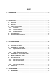
Index 1. INTRODUCTION ........................................................................................................................................ 4 2. SPECIFICATIONS ..................................................................................................................................... 5 3. SYSTEM REQUIREMENTS ..................................................................................................................... 6 4. INSTALLATION................................
7.1.2. Channel name ...................................................................................................................... 19 7.1.3. Computer & KVM status .................................................................................................... 20 7.1.4. Current active channel number ....................................................................................... 20 7.1.5. Cascade parent channel number .................................................................
1. Introduction Thank you for purchasing Edimax EK-08RC & EK-16RC PS/2 & USB Combo KVM Switch! EK-08RC/EK-16RC built-in 2 PS/2 ports and 2 USB ports for keyboard / mouse. You now have a high quality, durable system to control 8 or 16 computers through PS/2 and/or USB connection from one console (PS/2 & USB Mouse, PS/2 & USB Keyboard, and Monitor). z Features 1. Control your computers by a single set of keyboard / mouse / monitor. You can use PS/2 or USB keyboard / mouse to control your computers, 2.
z Package Contents The product you purchased should contain the following equipment and accessories: 1 x EK-08RC or EK-16RC Combo KVM Switch . 1 x User’s Manual. 1 x Power adaptor 1 x Rack Mount Kit 1 x 1.8 meters 4-in-1 combo cable Cable Order information : EK-C18C ( 1.8 meters ) ; EK-C30C ( 3 msters ) 2.
3. System Requirements z Console A VGA, SVGA, Multisync monitor capable of the highest resolution. PS/2 and/or USB Keyboard/Mouse z Computer or Server The following equipment must be equipped with each computer or server. A VGA, SVGA or Multisync card Type A USB port or PS/2 6 pin mini-DIN for Keyboard and Mouse. z Cables The Combo Free KVM Switch must be used specific custom 4-in-1 cables. To purchase the specific cable sets, please contact your dealer. Cable Order information : EK-C18C ( 1.
z Reset Switch : Press Reset switch when you want to reset the system. This switch must be pushed with a thin object like the end of a paper clip, or a ball point pen. 4.2. Rear View z EK-08RC Figure 3: 8-port KVM read view z EK-16RC Figure 4: 16-port KVM read view 4.3. Single stage installation 4.3.1. Precaution: ¾ Please turn off computers and devices when you start to install KVM Switch. ¾ For computers with Keyboard Power On function, please unplug the power cords in advance.
Fig. 1 Figure 5: Console connection 4.3.3. System connection: Please use Custom combo cable to connect your computers. Please refer to the figures and instruction shown below for System connection. Note: Please contact your dealer to purchase the 4-in-1 combo cables if you need. Order information : EK-C18C ( 1.
You can connect KVM switch to computers via three methods shown below: A. Connect USB, PS/2 (keyboard/mouse) and VGA connectors to computers. We recommand users to connect computers in this way. (Figure 7) Figure 7: USB & PS/2 (Keyboard & Mouse) and VGA connected B. Connect only PS/2 (keyboard/mouse) and VGA connectors to computers (Figure 8).
C. Connect only USB and VGA connectors to computers. (Figure 9). Figure 9: USB and VGA video connected 4.4. Cascade Chaining EK-08RC & EK-16RC KVM switch support 3 level cascades; control up to 64/256/4096 PCs, from a single console; cascaded units don’t need special configuration. Cascade configuration expands system ability and allows you to select computers connected to the Master or Slave. After connected, KVM Switches automatically configure Master and Slave.
E. Next, plug in power adapter for each level Slave KVM Switch and connect Slave KVM switch to computers . F. The power on sequence should be: 1. 2. Master KVM Switch Second level Slave KVM Switch (connecting to Master KVM Switch) if any. 3. Third level Slave KVM Switch (connecting to second level Slave KVM Switch) if any. 4. All computers connecting to Master/Slave KVM Switch. G. After all KVM Switches are powerd by power adaptor, trun on the computers.
Figure 10: Cascade chaining 4.5. Firmware download connector The min-USB female connector on the rear of KVM switch is for firmware upgrade function. To update your KVM firmware, please contact with your dealer.
4.6. Rack Mounting Figure 11: Rack mounting Figure 11 shows you how to attach mounting brackets to the KVM Switch unit for standard 19-inch rack cabinet. 1. Screw the mounting brackets into the sides of the KVM Switch unit. ( See Figure 11) 2. Install the KVM Switch unit into the rack cabinet. 5. Operation You can control computers via EK-08RC or EK-16RC Combo KVM Switch by push button, hot key and OSD. 1. Push button operation Press the front panel push button to select the PC and operate it. 2.
6. Hot Key Operation 6.1. Call OSD Menu Press < Scroll Lock> twice and , then the OSD “Main Menu” will be displayed on the monitor screen. All of the KVM parameters can be setup in OSD mode. You can also execute some KVM functions in OSD. → → 6.2. Leading Hot Key Select The two-steps hot key sequence is used for quick function execution. The leading key is by default. However, you can change the leading hot key if you want.
Figure 12: Specific channel selection hot key or or … … → → <1> → → → <2> → → → <16> → Note: You can also select computers in OSD menu. Move the indicator bar to the chanel to switch by using , or , then press to select the connected computer. Please refer section 7.2 Channel Selection in OSD. 6.3.2.
automatically shift to left or right one channel (channel decrease / increase to next) when < ALT > channel shift function is enabled. ¾ Enable/Disable channel shift function → → < ALT > → ¾ Switch to left one channel → < Left ALT > ¾ Switch to right one channel → < Right ALT > 6.4. Channel Select - Cascade Chain Layer You can select the active channel directly under cascade chain connection.
or , and then press to switch to the target port. Please refer section 7.2.2 Channel select to cascade port. 6.5. Buzzer sound Disable / Enable Press twice, then and . The buzzer sound will be disabled / enabled alternately. The buzzer sound default setting is ON. → → → Note: You can also enable/disable buzzer sound by pressing in OSD main menu. Please refer section 7.3.6 Setup in OSD - Sound. .
Figure 14: Auto-scan hot key ─┬── │ │ ┬ ──┬────── │ └─ └────────── └─────────────── Channel Name Channel Number Indicate now is Scan Mode Figure 15: Auto-scan Banner 6.6.2. Stop auto-scan function Press any key on keyboard to STOP the auto-scan function. Press the push button on KVM front panel to select active port can stop the auto-scan function too. 6.6.3. Auto-scan mode There are two auto-scan modes, please refer section 7.3.1 Setup in OSD – Scan Mode to setup the auto-scan mode.
you can lock console by pressing twice, and then and . The KVM will be locked until an authorized user login. → → → To unlock console, please press any key according to screen message, then key in User Name and Password. The KVM switch and console devices will be unlocked and back to normal status. Note: You can also execute console lock function by pressing in OSD main menu. Please refer section 7.5 Console Lock in OSD. 7.
¾ A plus mark (+) showing in the left of channel name indicates that the port has cascades. 7.1.3. Computer & KVM status ¾ KVM buzzer stauts Buzzer sound on Buzzer sound off ¾ Logined user name The system has one administrator and 3 users for security management. The name of current logined is displayed here. ¾ Channel LOCK indicator ( Status STA ) L: Indicating this channel is locked. BLANK: Indicating this channel is normal without locked.
first page, and information of port 9 ~ 16 are display in the second page. Since the port information is divide to two pages, the page down / up indicator can remind you to switch to alternative page by using and key. 7.1.7. Function Control Menu The detail of control functions will be described in later sections. The list of control functions: F1: Set up: basic set up menu F2: Scan: autoscan function F3: Lock: setup lock/unlock, only available when F5 Security is enabled.
┬ ┬ ┬ │ │ │ │ │ └─────── │ ────┬────── └ └────────── Channel Name Channel Number nd 2 Layer Channel Number └────────────── 1st Layer Channel Fig. 18: Channel Banner (Cascade Layer) Number 7.2.3. Return from cascade port After entering cascade port, press will return to upper layer OSD s menu. s 7.3. Setup in OSD: Please use or arrow key to select the item you want to change, and use or arrow key to change the settings.
7.3.2. Scan Time The default scan time is 5 seconds. It can be changed up to 90 seconds by stepping 5 seconds. 7.3.3. Banner Time The default banner time is 5 seconds. It can be changed to 10 seconds, 15 seconds, or always on (∞). 7.3.4. Position ¾ Menu: Use four arrow keys to move the OSD main menu to the desired position. Press to save the changed menu position. Figure 20: Menu Position Setup ¾ Banner: Use four arrow keys to move the channel banner to the desired position.
Note: You can also change leading hot key via hot key by using < CTRL > → < CTRL > → < New Hotkey > → < Enter > outside the OSD mode. Please refer section 6.2 Leading Hot Key Select. 7.3.6. Sound ¾ ON: Buzzer sound enabled. ¾ OFF: Buzzer sound disabled. Note: You can also enable/disable buzzer sound via hot key by using → → → outside the OSD mode. Please refer section 6.5 Buzzer sound Disable / Enable. 7.3.7.
7.4.3. Auto-scan mode There are two auto-scan modes, please refer section 7.3.1 Setup in OSD – Scan Mode to set up the auto-scan mode. ¾ Scan all computers which are power on. ¾ Scan all computers which are marked for auto-scan. 7.4.4. Auto-scan time interval The auto-scan time interval of each port displayed can be adjustable by pressing in OSD main menu. Please refer section 7.3.2 Setup in OSD – Scan Time. 7.5.
7.6. Channel rename: Select the channel to rename by using up/down arrow key and press in OSD main menu. The channel rename window will be shown for setting up the channel name. Press to save the renamed channel name or to cancel. Figure 25: Channel Rename window 7.7. Security Setup: 7.7.1. Security mode login Press in OSD main menu to enter security setup mode, the administrator login is required before entering into the security mode.
Figure 27: Security setup main window 7.7.2. Security Mode To change the security mode setting, please move the highlight bar to Security Mode, and press or key to change it. The Console Lock, Port Lock and user authority functions can not be executed until the security mode is enabled. 7.7.3. Change administrator password To change the administrator password, move the highlight bar to Admin/password, and press or key.
7.7.4. Authorized user setup 3 authorized users are admitted to manage the KVM switch. To change the user name and password, please move the highlight bar to the user for editing. Press or key, the user name and password setup window will be shown on the screen. Please Input the new user’s name and password twice, then press to confirm or to cancel. Figure 29: User name password setup window 7.7.5. User Authority setup You can setup the authority for each user.
7.8. Lock Port: 7.8.1. Lock Port Only administrator can lock port. Please move the highlight bar to the channel to lock, and press to lock the selected channel. A red L mark will be shown in STA column of locked port. Figure 31: Lock port in OSD main window 7.8.2. Channel selection of the locked port If anyone selects the channel of the locked port either by panel push-button or hot key, the system will enter OSD mode waiting for administrator to unlock the port. 7.8.3.
8. Sun Microsystems Function Key Emulation: There are 16 special functions on the Sun Microsystems keyboard, Combo Free KVM Switch can emulate these function keys via PS/2 and/or USB keyboard. Please refer to the table shown below for Sun Microsystems keyboard special functions operation. To active these emulation on the PS/2 and/or USB keyboard, you have to press the key first (this key usually is located between the and ).
9. Troubleshooting : Symptom Keyboard and/or Mouse not working. Possible Cause Keyboard and/or Mouse need to be reset Failed connection to the computer. KVM Switch needs to be reset Master/ Slave daisy chained doesn’t work Incorrect configuration or improper installation procedures Double OSD images at cascade configuration Improper slave connection procedure.
Disclaimer Information in this document is subject to change without notice. The manufacturer does not make any representations or warranties (implied or otherwise) regarding the accuracy and completeness of this document and shall in no event be liable for any loss of profit or any other commercial damage, including but not limited to special, incidental, consequential, or other damages.