Multi-Homing Broadband Router User Manual 1
Introduction....................................................................................................................... 4 Features.............................................................................................................................. 4 Minimum Requirements .................................................................................................. 4 Package Content .......................................................................................................
2.5 Firewall ...................................................................................................................... 62 2.5.1 Access Control........................................................................................................ 63 2.5.2 URL Blocking......................................................................................................... 67 2.5.3 DoS (Denial of Service)..........................................................................................
Introduction Congratulations on purchasing this Multi-homing Broadband router. This is a cost-effective IP Sharing Router that enables multiple users to share the Internet through up to two ADSL or cable modems. Simply configure your Internet connection settings in the router and plug your PC to the router’s LAN port and you're ready to share files and access the Internet.
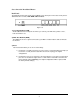
Get to know the Broadband Router Back Panel The diagram (fig1.0) below shows the broadband router’s back panel. The router’s back panel is divided into three sections, LAN, WAN, USB and Reset: Figure 1.0 1) Local Area Network (LAN) The Broadband router’s LAN ports are where you connect your LAN’s PCs, printer servers, hubs and switches etc. 2) Wide Area Network (WAN) The WAN ports are the segment connected to your xDSL or Cable modems and are linked to the Internet.
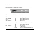
Front Panel On the router’s front panel there are LED lights that inform you of the router’s current status. Below is an explanation of each LED and its description.
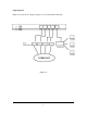
Setup Diagram Figure 1.2 below shows a typical setup for a Local Area Network (LAN). Figure 1.
Getting started This is a step-by-step instruction on how to start using the router and get connected to the Internet. 1) Setup your network as shown in the setup diagram above (fig 1.2). 2) You then need to set your LAN PC clients so that it can obtain an IP address automatically. All LAN clients require an IP address. Just like an address, it allows LAN clients to find one another.
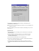
8: Reboot the PC. Your PC will now obtain an IP address automatically from your Broadband Router’s DHCP server. Note: Please make sure that the Broadband router’s DHCP server is the only DHCP server available on your LAN. Once you’ve configured your PC to obtain an IP address automatically, please proceed to Step 3 (Page 11). 2b) Windows 2000 1: Click the Start button and select Settings, then click Control Panel. The Control Panel window will appear. 2: Double-click Network and Dial-up Connections icon.
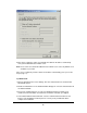
6: Click OK to confirm the setting. Your PC will now obtain an IP address automatically from your Broadband Router’s DHCP server. Note: Please make sure that the Broadband router’s DHCP server is the only DHCP server available on your LAN. Once you’ve configured your PC to obtain an IP address automatically, please proceed to Step 3 (Page 11). 2c) Windows NT 1: Click the Start button and select Settings, then click Control Panel. The Control Panel window will appear. 2: Double-click Network icon.
5: After you install TCP/IP, go back to the Network window. Select TCP/IP from the list of Network Protocols and then click the Properties button. 6: Check each of the tabs and verify the following settings: • IP Address: Select Obtain an IP address from a DHCP server. • DNS: Let all fields are blank. • WINS: Let all fields are blank. • Routing: Let all fields are blank. 7: Click OK to confirm the setting. Your PC will now obtain an IP address automatically from your Broadband Router’s DHCP server.
Broadband Router’s DHCP server is enabled so that you can obtain an IP address automatically. To see if you have obtained an IP address, see Appendix A. Note: Please make sure that the Broadband router’s DHCP server is the only DHCP server available on your LAN. If there is another DHCP on your network, then you’ll need to switch one of the DHCP servers off.
The Status Information section is for you to monitor the router’s current status information only. Tools (Chapter 4) If you want to Reset the router (because of problems) or save your configurations or upgrade the firmware then the Tools section is the place to do this. Menu Description Quick Setup Wizard (Chapter 1) Select your Internet connection type and then input the configurations needed to connect to your Internet Service Provider (ISP).
Device Status, Security Log and DHCP client Log information. Tools (Chapter 4) This section contains the broadband router’s Tools - Tools include Configuration tools, Firmware upgrade and Reset. Configuration tools allow you to Backup (save), Restore, or Restore to Factory Default configuration for your Broadband router. The Firmware upgrade tool allows you to upgrade your Broadband router's firmware. The RESET tool allows you to reset your Broadband router.
Chapter 1 Quick Setup The Quick Setup section is designed to get you using the broadband router as quickly as possible. In the Quick Setup you are required to fill in only the information necessary to access the Internet. Once you click on the Quick Setup Wizard in the HOME page, you should see the screen below. Step 1) Time Zone The Time Zone allows your router to base its time on the settings configured here, this will affect functions such as Log entries and Firewall settings.
Start Daylight Savings Time Select the period in which you wish to start daylight Savings Time End Daylight Savings Time Select the period in which you wish to end daylight Savings Time Click on NEXT to proceed to the next page (step 2) Broadband Type. Step 2) Broadband Type In this section you have to select one of four types of connections that you will be using to connect your broadband router’s WAN port to your ISP (see screen below).
1.3 PPPoE Your ISP requires you to use a Point-to-Point Protocol over Ethernet (PPPoE) connection. 1.4 PPTP Your ISP requires you to use a Point-to-Point Tunneling Protocol (PPTP) connection. 1.5 L2TP Your ISP requires you to use a Layer Two Tunneling Protocol (PPTP) connection. 1.4 Telstra Big Pond This Protocol only used for Australia’s ISP connection. Click on one of the WAN type and then proceed to the manual’s relevant sub-section (1.1, 1.2, 1.3, 1.4, 1.5 or 1.6).
Parameters Host Name Description MAC Address Your ISP may require a particular MAC address in order for you to connect to the Internet. This MAC address is the PC’s MAC address that your ISP had originally connected your Internet connection to. Type in this MAC address in this section or use the “Clone MAC Address” button to replace the WAN MAC address with the MAC address of that PC (you have to be using that PC for the Clone MAC Address button to work). To find out the PC’s MAC address see Appendix A.
Parameters Description IP This is the IP address that your ISP has given you. Gateway IP This is the ISP’s IP address gateway DNS This is the ISP’s DNS server IP address Subnet Mask Enter the Subnet Mask provided by your ISP (e.g. 255.255.255.0) Click when you have finished the configuration above. Congratulations! You have completed the configuration for the Fixed-IP x DSL connection.
Parameter Description User Name Enter the User Name provided by your ISP for the PPPoE connection Password Enter the Password provided by your ISP for the PPPoE connection Service Name This is optional. Enter the Service name should your ISP requires it, otherwise leave it blank. MTU This is optional. You can specify the maximum size of your transmission packet to the Internet. Leave it as it is if you to not wish to set a maximum packet size.
1.4 PPTP Select PPTP if your ISP requires the PPTP protocol to connect you to the Internet. Your ISP should provide all the information required in this section. Parameter Description Obtain an IP address automatically The ISP requires you to obtain an IP address by DHCP before connecting to the PPTP server. Use the following IP address The ISP gives you a static IP to be used to connect to the PPTP server. IP Address This is the IP address that your ISP has given you to establish a PPTP connection.
Password Enter the Password provided by your ISP for the PPTP connection PPTP Gateway If your LAN has a PPTP gateway, then enter that PPTP gateway IP address here. If you do not have a PPTP gateway then enter the ISP’s Gateway IP address above Connection ID This is the ID given by ISP. This is optional. MTU This is optional. You can specify the maximum size of your transmission packet to the Internet. Leave it as it is if you to not wish to set a maximum packet size.
Click when you have finished the configuration above. Congratulations! You have completed the configuration for the PPTP connection. You can start using the router now, if you wish to use some of the advance features supported by this router see chapter 2, 3, 4. 1.5 L2TP Select L2TP if your ISP requires the L2TP protocol to connect you to the Internet. Your ISP should provide all the information required in this section.
Use the following IP address The ISP gives you a static IP to be used to connect to the L2TP server. IP Address This is the IP address that your ISP has given you to establish a L2TP connection. Subnet Mask Enter the Subnet Mask provided by your ISP (e.g. 255.255.255.0) Gateway Enter the IP address of the ISP Gateway User ID Enter the User Name provided by your ISP for the PPTP connection.
to prevent from extra fee charged by ISP, please TURN OFF THE ROUTER WHEN YOU FINISHED USING THE INTERNET. Click when you have finished the configuration above. Congratulations! You have completed the configuration for the L2TPP connection. You can start using the router now, if you wish to use some of the advance features supported by this router see chapter 2, 3, 4. 1.6 Telstra Big Pond Select Telstra Big Pond if your ISP requires the Telstra Big Pond protocol to connect you to the Internet.
manually server manually. Login Server The IP of the Login Server. Click when you have finished the configuration above. Congratulations! You have completed the configuration for the Telstra Big Pond connection. You can start using the router now, if you wish to use some of the advance features supported by this router see chapter 2, 3, 4.
Chapter 2 General Settings Once you click on the General Setup button at the Home Page, you should see the screen below. If you have already configured the Quick Setup Wizard you do NOT need to configure anything thing in the General Setup screen for you to start using the Internet.
2.2 WAN 2.3 LAN This section allows you to select the connection method in order to establish a connection with your ISP (same as the Quick Setup Wizard section) You can specify the LAN segment’s IP address, subnet Mask, enable/disable DHCP and select an IP range for your LAN 2.4 NAT You can configure the Address Mapping, Virtual Server and Special Applications functions in this section. This allows you to specify what user/packet can pass your router’s NAT. 2.
Parameters System Settings Description 2.1.1 Time Zone Select the time zone of the country you are currently in. The router will set its time based on your selection. 2.1.2 Password Settings Allows you to select a password in order to access the web-based management website. 2.1.3 Remote Management You can specify a Host IP address that can perform remote management functions. Select one of the above three system settings selections and proceed to the manual’s relevant sub-section 2.1.
Time Server Address You can manually assign time server address if the default time server did not work. Enable Daylight Savings The router can also take Daylight savings into account. If you wish to use this function, you must check/tick the enable box to enable your daylight saving configuration (below).
Parameters Current Password Description New Password Enter your new password Confirmed Password Enter your new password again for verification purposes Enter your current password for the remote management administrator to login to your Broadband router.
Host Address This is the IP address of the host in the Internet that will have management/configuration access to the Broadband router from a remote site. This means if you are at home and your home IP address has been designated the Remote Management host IP address for this router (located in your company office), then you are able to configure this router from your home. If the Host Address is left 0.0.0.
2.2 WAN Use the WAN Settings screen if you have already configured the Quick Setup Wizard section and you would like to change your Internet connection type. The WAN Settings screen allows you to specify the type of WAN port connect you want to establish with your ISP. The WAN settings offer the following selections for the router’s WAN port, Dynamic IP, Static IP, PPPoE, PPTP, L2TP, Telstra Big Pond, Qos, Policy, DNS and DDNS.
2.2.8 QoS You can specify rules for bandwidth control. 2.2.9 DNS You can specify a DNS server that you wish to use 2.2.10 DDNS You can specify a DDNS server that you wish to use and configure the user name and password provided by you DDNS service provider. Once you have made a selection, click at the bottom of the screen and proceed to the manual’s relevant sub-section 2.2.1 Dynamic IP Choose the Dynamic IP selection if your ISP will automatically give you an IP address.
Parameter Description Obtain an IP address automatically The ISP requires you to obtain an IP address by DHCP before connecting to the L2TP server. MAC Address Your ISP may require a particular MAC address in order for you to connect to the Internet. This MAC address is the PC's MAC address that your ISP had originally connected your Internet connection to.
(e.g. 255.255.255.0) Gateway Enter the IP address of the ISP Gateway User ID Enter the User Name provided by your ISP for the PPTP connection. Sometimes called a Connection ID Password Enter the Password provided by your ISP for the PPTP connection L2TP Gateway If your LAN has a L2TP gateway, then enter that L2TP gateway IP address here. If you do not have a L2TP gateway then enter the ISP’s Gateway IP address above MTU This is optional.
2.2.6 Telstra Big Pond Select Telstra Big Pond if your ISP requires the Telstra Big Pond protocol to connect you to the Internet. Your ISP should provide all the information required in this section. Telstra Big Pond protocol is used by the ISP in Australia.
2.2.7 WAN Policy The WAN policy for multi-homing can be setup here. You can setup policy for each WAN separately. The router will balance the load between all active WAN ports according to the Send/Receive rate of the WAN ports. You can setup an IP for the router to detect if the WAN line is connected. If the router fails to ping the IP, it would recognize the WAN line as not connected, and will stop directing the Internet traffic to this WAN port.
“Backup”, the WAN port is disabled on start up. But when other enabled WAN ports fail, the backup WAN port will be activated and take over all the traffic. Click when you have finished the configuration above. Congratulations! You have completed the configuration for the Telstra Big Pond connection. You can start using the router now. 2.2.8 QoS The QoS can let you classify Internet application traffic by source/destination IP, MAC address and port number.
Parameters Description Enable/Disable QoS You can check “Enable QoS” to enable QoS function for the WAN port. You also can uncheck “Enable QoS” to disable QoS function for the WAN port. Add a QoS rule into the table Click “Add” then you will enter a form of the QoS rule. Click “Apply” after filling out the form and the rule will be added into the table.
rule and click “Move Down” to make its priority lower. QoS Rule: You can assign packet classification criteria by its source IP range, source MAC address, destination IP range, traffic type, protocol, source port range and destination port range parameters. The parameters that you leave as blank will be ignored. The priority of this rule will be applied to packets that match classification criteria of this rule.
Bandwidth You can assign the bandwidth by the unit of Kbps (1024 bit per second). You can limit the maximum bandwidth consumed by this rule by selecting “Maximum”. You also can reserve enough bandwidth for this rule by selecting “Guarentee”. Source Address You can select IP or MAC address as the source address criteria. Source MAC Address Enter the MAC address of the packet that this rule will apply to. Source IP Address Enter the source IP address range of the packets that this rule will apply to.
to port number 150 – the range of 50 port numbers. Apply Apply and exit the form. Reset Clear the content of this form. Click at the bottom of the screen to save the above configurations. You can now configure other advance sections or start using the router (with the advance settings in place) 2.2.9 DNS A Domain Name System (DNS) server is like an index of IP addresses and Web addresses. If you type a Web address into your browser, such as www.router.
Domain Name Server (DNS) address This is the ISP’s DNS server IP address that they gave you; or you can specify your own preferred DNS server IP address Secondary DNS Address (optional) It is optional. You can enter another DNS server’s IP address as a backup. The secondary DNS will be used should the above DNS fail. Click at the bottom of the screen to save the above configurations. You can now configure other advance sections or start using the router (with the advance settings in place) 2.2.
Enable/Disable Disable Enable/Disable the DDNS function of this router Provider DynDNS Select a DDNS service provider Domain name Your static domain name that use DDNS Account/E-mail The account that your DDNS service provider assigned to you Password/Key The password you set for the DDNS service account above Click at the bottom of the screen to save the above configurations.
2.3 LAN The LAN Port screen below allows you to specify a private IP address for your router’s LAN ports as well as a subnet mask for your LAN segment. Parameters Default Description LAN IP IP address 192.168.2.1 This is the router’s LAN port IP address (Your LAN clients default gateway IP address) IP Subnet Mask 255.255.255.0 Specify a Subnet Mask for your LAN segment 802.1d Spanning Tree Disabled If 802.
same subnet as this broadband router if you want the router to be your LAN client’s default gateway Lease Time The DHCP when enabled will temporarily give your LAN clients an IP address. In the Lease Time setting you can specify the time period that the DHCP lends an IP address to your LAN clients.
2.4 NAT Network Address Translation (NAT) allows multiple users at your local site to access the Internet through a single Public IP Address or multiple Public IP Addresses. NAT provides Firewall protection from hacker attacks and has the flexibility to allow you to map Private IP Addresses to Public IP Addresses for key services such as Websites and FTP. You also can disable NAT function and use the static route.
2.4.1 Port Forwarding The Port Forwarding allows you to re-direct a particular range of service port numbers (from the Internet/WAN Ports) to a particular LAN IP address. It helps you to host some servers behind the router NAT firewall. Parameter Description Enable Port Forwarding Enable Port Forwarding Private IP This is the private IP of the server behind the NAT firewall. Note: You need to give your LAN PC clients a fixed/static IP address for Port Forwarding to work properly.
Comment The description of this setting. Add Port Forwarding into the table Fill in the "Private IP", “Type”, “Port Range”, “WAN Port” and "Comment" of the setting to be added and then click "Add". Then this Port Forwarding setting will be added into the "Current Port Forwarding Table" below. If you find any typo before adding it and want to retype again, just click "Clear" and the fields will be cleared.
2.4.2 Virtual Server Use the Virtual Server function when you want different servers/clients in your LAN to handle different service/Internet application type (e.g. Email, FTP, Web server etc.) from the Internet. Computers use numbers called port numbers to recognize a particular service/Internet application type. The Virtual Server allows you to re-direct a particular service port number (from the Internet/WAN Port) to a particular LAN private IP address and its service port number.
Public Port Enter the service (service/Internet application) port number from the Internet that will be re-directed to the above Private IP address host in your LAN Note: Virtual Server function will have priority over the DMZ function if there is a conflict between the Virtual Server and the DMZ settings. WAN Port Assign the WAN port that you want to bind to the virtual server.
Example: Virtual Server The diagram below demonstrates one of the ways you can use the Virtual Server function. Use the Virtual Server when you want the web server located in your private LAN to be accessible to Internet users. The configuration below means that any request coming form the Internet to access your web server will be translated to your LAN’s web server (192.168.2.2). Note: For the virtual server to work properly Internet/remote users must know your global IP address.
2.4.3 Special Applications Some applications require multiple connections, such as Internet games, video conferencing, Internet telephony and others. In this section you can configure the router to support multiple connections for these types of applications. Parameters Description Enable Trigger Port Enable the Special Application function.
Comment The description of this setting. Popular applications This section lists the more popular applications that require multiple connections. Select an application from the Popular Applications selection. Once you have selected an application, select a location (1-10) in the Copy to selection box and then click the Copy to button. This will automatically list the Public Ports required for this popular application in the location (1-10) you’d specified.
2.4.4 UPnP With UPnP, all PCs in you Intranet will discover this router automatically. So you do not have to do any configuration for your PC and can access the Internet through this router easily. Parameters Default Description UPnP Feature Disable You can Enable or Disable UPnP feature here. After you enable the UPnP feature, all client systems that support UPnP, like Windows XP, can discover this router automatically and access the Internet through this router without any configuration.
2.4.5 Protocol and Port Binding Protocol and Port Binding let you manually bind an application to a WAN port. Only packets that match all the entered criteria will be bound to the assigned WAN port. You can have to fill all the items. The items that you leave blank will be ignored. Parameters Description Enable Protocol & Port Binding The “Protocol and Port Binding” function is default disabled. You can select to enable the “Protocol and Port Binding” function.
Protocol Only packets with this assigned protocol will statically bind to the assigned WAN port. WAN Port The WAN port that the packets matching this rule are statically bound to. Add a Rule Fill in the "Source IP Range", "Destination IP Range”, “Source Port Range”, "Destination Port Range", "Protocol" or "WAN Port" of the setting to be added and then click "Add". Then this rule of Protocol and Port Binding will be added into the "Protocol and Port Binding Table" below.
2.4.6 ALG Settings You can select applications that need “Application Layer Gateway” to support. Parameters Enable Default Description You can select to enable “Application Layer Gateway”, then the router will let that application correctly pass though the NAT gateway. Click at the bottom of the screen to save the above configurations. You can now configure other advance sections or start using the router (with the advance settings in place) 2.4.
Parameter Description Enable Static Routing Static Routing function is default disabled. You have to enable the Static Routing function before your routing rules take effect. Destination LAN IP The network address of destination LAN. Subnet Mask The subnet mask of destination LAN. Default Gateway The next stop gateway of the path toward the destination LAN. This is the IP of the neighbor router that this router should communicate with on the path to the destination LAN.
rule of Static Routing will be added into the "Static Routing Table" below. If you find any typo before adding it and want to retype again, just click "Clear" and the fields will be cleared. Remove a Rule If you want to remove some routing rules from the "Static Routing Table", select the rules you want to remove in the table and then click "Delete Selected". If you want remove all rules from the table, just click "Delete All" button. Click "Reset" will clear your current selections.
2.5 Firewall The Broadband router provides extensive firewall protection by restricting connection parameters, thus limiting the risk of hacker attack, and defending against a wide array of common Internet attacks. However, for applications that require unrestricted access to the Internet, you can configure a specific client/server as a Demilitarized Zone (DMZ). Note: To enable the Firewall settings select Enable and click Apply Parameters Description 2.5.
2.5.1 Access Control If you want to restrict users from accessing certain Internet applications/services(e.g. Internet websites, email, FTP etc.), then this is the place to set that configuration. Access Control allows users to define the traffic type permitted in your LAN. You can control which PC client can have access to these services. Parameters Description Filter client PCs by IP Fill “IP Filtering Table” to filter PC clients by IP.
Add PC Fill in “Client PC MAC Address” and “Comment” of the PC that is allowed to access the Internet, and then click “Add”. If you find any typo before adding it and want to retype again, just click "Reset" and the fields will be cleared. Remove PC If you want to remove some PC from the "MAC Filtering Table", select the PC you want to remove in the table and then click "Delete Selected". If you want remove all PCs from the table, just click "Delete All" button.
Client PC IP Address Enter the IP address that you wish to apply this Access Control rule. This is the user’s IP address that you wish to setup an Access Control rule. Note: You need to give your LAN PC clients a fixed/static IP address for the Access Control rule to work properly. Client PC Service You can block the clients from accessing some Internet services by checking the services you want to block. Protocol This allows you to select UDP, TCP or both protocol type you want to block.
Example: Access Control In the example below, LAN client A can only access websites that use Port 80. However, LAN client B is able to access websites and any other service that uses ports between 80 and 999.
2.5.2 URL Blocking You can block access to some Web sites from particular PCs by entering a full URL address or just keyword of the Web site. Parameters Description Enable URL Blocking Enable/disable URL Blocking Add URL Keyword Fill in “URL/Keyword” and then click “Add”. You can enter the full URL address or the keyword of the web site you want to block. If you find any typo before adding it and want to retype again, just click "Reset" and the field will be cleared.
You can now configure other advance sections or start using the router (with the advance settings in place) 2.5.3 DoS (Denial of Service) The Broadband router's firewall can block common hacker attacks, including Ping of Death, Discard Ping from WAN, Port Scan, and Sync Flood. If Internet attacks occur the router can log the events.
Parameters Description Intrusion Detection Feature Ping of Death Protections from any Ping of Death attacks. If you go to the advanced setting page, you can configure the threshold of the frequency of packets occurred. Discard Ping From WAN The router’s WAN port will not respond to any Ping requests Port Scan Protection from any Port Scan attacks. If you go to the advanced setting page, you can configure the pattern of Port Scan you want to prevent.
2.5.4 DMZ If you have a local client PC that cannot run an Internet application (e.g. Games) properly from behind the NAT firewall, then you can open the client up to unrestricted two-way Internet access by defining a DMZ Host. The DMZ function allows you to re-direct all packets going to your WAN port IP address to a particular IP address in your LAN. The difference between the virtual server and the DMZ function is that the virtual server re-directs a particular service/Internet application (e.g.
Client PC IP Address Input the IP address of a particular host in your LAN that will receive all the packets originally going to the WAN port/Public IP address above Note: You need to give your LAN PC clients a fixed/static IP address for DMZ to work properly. Add DMZ Fill in the "WAN Port", "Public IP Address” and “Client IP Address” of the DMZ to be added and then click "Add". Then this DMZ entry will be added into the "DMZ Table" below.
Chapter 3 Status The Status section allows you to monitor the current status of your router. You can use the Status page to monitor: the connection status of the Broadband Router's WAN/LAN interfaces, the current firmware and hardware version numbers, any illegal attempts to access your network, and information on all DHCP client PCs currently connected to your network. Parameters Description 3.1 Status and Information Shows the router’s system information 3.
3.
3.2 Internet Connection View the Broadband router’s current Internet connection status and other related information Parameters Description Internet Connection This page displays whether the WAN ports are connected to Cable/DSL connections. It also displays the router’s WAN port: WAN IP address, Subnet Mask, and ISP Gateway as well as the Primary DNS and Secondary DNS being used.
3.3 Device Status View the Broadband router’s current configuration settings. The Device Status displays the configuration settings you’ve configured in the Quick Setup Wizard/General Setup section. Parameters Description Device Status This page shows the Broadband router’s current device settings. This page displays the Broadband router LAN port’s current LAN IP Address and Subnet Mask. It also shows whether the DHCP Server.
3.4 System Log View the operation log of the system. Parameters Description System Log This page shows the current system log of the Broadband router. It displays any event occurred after system start up. At the bottom of the page, the system log can be saved to a local file for further processing or the system log can be cleared or it can be refreshed to get the most updated situation. When the system is powered down, the system log will disappear if not saved to a local file.
3.5 Security Log View any attempts that have been made to illegally gain access to your network. Parameters Description Security Log This page shows the current security log of the Broadband router. It displays any illegal attempts to access your network. At the bottom of the page, the security log can be saved to a local file for further processing or the security log can be cleared or it can be refreshed to get the most updated situation.
3.6 Active DHCP Client View your LAN client's information that is currently linked to the Broadband router's DHCP server Parameters Description DHCP Client Log This page shows all DHCP clients (LAN PCs) currently connected to your network. The “Active DHCP Client Table” displays the IP address and the MAC address and Time Expired of each LAN Client.
3.7 Statistics View the statistics of packets sent and received on each WAN and LAN interface. Parameters Statistics Description Shows the counters of packets sent and received on WAN and LAN.
Chapter 4 Tool This page includes the basic configuration tools, such as Configuration Tools (save or restore configuration settings), Firmware Upgrade (upgrade system firmware) and Reset. Parameters Description 4.1 Configuration Tools You can save the router’s current configuration, restore the router’s saved configuration files and restore the router’s factory default settings 4.2 Firmware Upgrade This page allows you to upgrade the router’s firmware 4.
4.1 Configuration Tools The Configuration Tools screen allows you to save (Backup) the router’s current configuration setting. Saving the configuration settings provides an added protection and convenience should problems occur with the router and you have to reset to factory default. When you save the configuration setting (Backup) you can re-load the saved configuration into the router through the Restore selection.
4.2 Firmware Upgrade This page allows you to upgrade the router’s firmware Parameters Description Firmware Upgrade This tool allows you to upgrade the Broadband router’s system firmware. To upgrade the firmware of your Broadband router, you need to download the firmware file to your local hard disk, and enter that file name and path in the appropriate field on this page. You can also use the Browse button to find the firmware file on your PC.
Parameters Description Reset In the event that the system stops responding correctly or in some way stops functioning, you can perform a reset. Your settings will not be changed. To perform the reset, click on the button. You will be asked to confirm your decision. The reset will be complete when the power light stops blinking. Once the reset process is complete you may start using the router again.
Appendix A How to Manually find your PC’s IP and MAC address 1) In Window’s open the Command Prompt program 2) Type Ipconfig /all and • • • Your PC’s IP address is the one entitled IP address (192.168.1.77) The router’s IP address is the one entitled Default Gateway (192.168.1.
Glossary Default Gateway (Router): Every non-router IP device needs to configure a default gateway’s IP address. When the device sends out an IP packet, if the destination is not on the same network, the device has to send the packet to its default gateway, which will then send it out towards the destination. DHCP: Dynamic Host Configuration Protocol. This protocol automatically gives every computer on your home network an IP address.
ISP: Internet Service Provider. An ISP is a business that provides connectivity to the Internet for individuals and other businesses or organizations. LAN: Local Area Network. A LAN is a group of computers and devices connected together in a relatively small area (such as a house or an office). Your home network is considered a LAN. MAC Address: MAC stands for Media Access Control. A MAC address is the hardware address of a device connected to a network.
create IP address numbers used only within a particular network (as opposed to valid IP address numbers recognized by the Internet, which must be assigned by InterNIC). TCP/IP, UDP: Transmission Control Protocol/Internet Protocol (TCP/IP) and Unreliable Datagram Protocol (UDP). TCP/IP is the standard protocol for data transmission over the Internet. Both TCP and UDP are transport layer protocol. TCP performs proper error detection and error recovery, and thus is reliable.