AR-7211A V2 / AR-7211B V2 User Manual 10-2012 / v1.
COPYRIGHT Copyright Edimax Technology Co., Ltd. all rights reserved. No part of this publication may be reproduced, transmitted, transcribed, stored in a retrieval system, or translated into any language or computer language, in any form or by any means, electronic, mechanical, magnetic, optical, chemical, manual or otherwise, without the prior written permission from Edimax Technology Co., Ltd. Edimax Technology Co., Ltd.
Contents 1. PRODUCT INTRODUCTION ..................................................................................................................... 5 1.1. 1.2. 1.3. 1.4. 1.5. PACKAGE CONTENTS............................................................................................................................ 5 SYSTEM REQUIREMENTS ....................................................................................................................... 5 SAFETY PRECAUTIONS .............................
5.6. ADVANCED ...................................................................................................................................... 67 5.6.1. Routing ................................................................................................................................. 67 5.6.2. NAT ...................................................................................................................................... 69 5.6.3. IP QoS .................................................
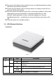
1. Product Introduction 1.1. Package Contents Before you start using this product, please check if there is anything missing in the package and contact your dealer to claim the missing item(s): ADSL2+ router (AR-7211A V2 or AR-7211B V2) Power adapter 1 meter RJ-45 Ethernet cable 1.8M RJ-11 telephone line x 2 Quick installation guide CD containing setup wizard, user manual & multi-language QIG 1.2. System Requirements Recommended system requirements are as follows.
Do not put this device close to heat sources or high temperatures. Keep the device out of direct sunshine. Do not put this device close to a place where it is damp or wet. Do not spill any fluid on this device. Do not connect this device to any PCs or electronic products, other than those which you are instructed or recommended to do so in the product’s documentation, by our customer engineers or by your broadband provider – connecting to incorrect devices may cause a fire risk.
Internet Green Red LAN Green ON BLINK OFF ON ON BLINK OFF Internet connected in router mode Internet activity (transferring/receiving data) in router mode Device in bridged mode Internet not connected in router mode (Please refer to Note 2) LAN port connected LAN activity (transferring/receiving data) LAN port not connected Note: 1) If the ADSL LED is off, please check your Internet connection. Refer to A . Hardware Installation for more information about how to connect the router correctly.
1.5. Features The device supports the following features: Various line modes External PPPoE dial-up access Internal PPPoE/PPPoA dial-up access 1483Briged/1483Routed/MER/IPoA access Multiple PVCs (up to eight) which can be isolated from each other A single PVC with multiple sessions Multiple PVCs with multiple sessions 802.1Q and 802.
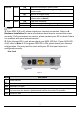
2. Hardware Installation Step 1. Connect the ADSL line Connect the Line interface of the device to the Modem interface of a splitter using a telephone cable. Connect a telephone to the Phone interface of the splitter using a telephone cable. Connect the Line interface of the splitter to your existing, incoming line. The splitter has three interfaces: Line: Connect to a wall phone jack (RJ-11 jack). Modem: Connect to the ADSL jack of the device. Phone: Connect to a telephone set. Step 2.
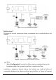
Figure 1 – No telephone before the splitter Configuration 2 0 shows the correct connection when a telephone set is installed before the splitter. Figure 2 - Telephone set connected before the splitter Note: When Configuration 2 is used, the filter must be installed close to the telephone cable. Do not use the splitter to replace the filter.
access, or slow connection speed. If you really need to add a telephone set before the splitter, you must add a micro filter before a telephone set. Do not connect several telephones before the splitter or connect several telephones with the micro filter. Step 4. Check the ADSL LED status Please check the ADSL LED on the front panel. This light indicates the status of your ADSL broadband through your telephone line. If the light is on, you can continue setup.
2. Click “Switch to Classic View” in the top left to show additional setting icons. 3. Locate the “Network Connections” icon and double-click to open network connection settings.
4. Select the “Local Area Connection” icon and right-click it to open the submenu, then select “Properties”. 5.
6. Ensure that “Obtain an IP address automatically” and “Obtain DNS server address automatically” are selected and then press “OK”.
3. IP Address Setting To use the router to access the Internet, the PCs in the network must have an Ethernet adapter installed and be connected to the router either directly or through a hub or switch. The TCP/IP protocol of each PC has to been installed and the IP Address of each PC has to be set in the same subnet as the router. The router’s default IP Address is 192.168.2.1 and the subnet mask is 255.255.255.0.
4. In the Internet Protocol Version 4 (TCP/IPv4) Properties window, select Obtain an IP address automatically and Obtain DNS server address automatically as shown on the following screen. 5. Click OK to confirm the setting. Your PC will now obtain an IP address automatically from your router’s DHCP server. Note: Please make sure that the router’s DHCP server is the only DHCP server available on your LAN. 3.2. Windows Vista 1. Click the Start button and select Settings and then select Control Panel.
3. Check your list of Network Components. You should see Internet Protocol Version 4 (TCP/IPv4) on your list. Select it and click the Properties button. 4. In the Internet Protocol Version 4 (TCP/IPv4) Properties window, select Obtain an IP address automatically and Obtain DNS server address automatically as shown on the following screen. 5. Click OK to confirm the setting. Your PC will now obtain an IP address automatically from your router’s DHCP server.
3. Check your list of Network Components. You should see Internet Protocol [TCP/IP] on your list. Select it and click the Properties button. 4. In the Internet Protocol (TCP/IP) Properties window, select Obtain an IP address automatically and Obtain DNS server address automatically as shown on the following screen. 5. Click OK to confirm the setting. Your PC will now obtain an IP address automatically from your router’s DHCP server.
4. EZmax Setup Wizard You can configure the router by running the setup wizard on the CD-ROM included in the package contents. The wizard enables you to configure your Internet connection, upgrade the firmware and change the router’s password. Please follow the instructions below. Alternatively, if you lose the CD-ROM or prefer a web based setup, you can login to the ADSL router using Internet Explorer, and configure the router from there using the web-based interface.
2. Please select your product.
3. Please ensure all hardware is correctly installed.
4. Select your country and ISP. If your ISP is not listed, select “Other” from the list and refer to 4.2. Internet Connection Type.
5. Enter your ISP’s username and password and click “Apply”. On the next screen, click “Apply” again.
6. Please wait while the router connects to the Internet. When the router is connected successfully, you will see the screen below.
4.2.Internet Connection Type If your country or ISP is not listed, please select “Other” from the list. Then select your Internet connection type and click “Next”. If you are not sure, please contact your Internet Service Provider (ISP). Depending on your selection, please refer to the appropriate chapter 4.1.1.1. PPPoE/PPPoA, 4.1.1.2. Bridge Mode, 4.1.1.3. Dynamic IP Address or 4.1.1.4. Static IP.
Parameter PPPoE/PPPoA Description PPPoE (PPP over Ethernet) and PPPoA (PPP over ATM) are common connection methods used for xDSL. Bridge Mode Bridge Mode is a common connection method used for xDSL modems. Dynamic IP Address Obtain an IP address automatically from your service provider. Static IP Address Uses a static IP address. Your service provider gives a static IP address to access Internet services. 4.2.1.1.
Parameter User Name Description Enter the username exactly as your ISP assigned. Password Enter the password that your ISP has assigned to you. VPI Virtual path identifier (VPI) is the virtual path between two points in an ATM network. Its valid value is in the range of 0 to 255. Enter the correct VPI provided by your ISP. By default, VPI is set to 8. VCI Virtual channel identifier (VCI) is the virtual channel between two points in an ATM network.
4.2.1.2. Bridge Mode Parameter VPI VCI Connection Type Description Virtual path identifier (VPI) is the virtual path between two points in an ATM network. Its valid value is in the range of 0 to 255. Enter the correct VPI provided by your ISP. By default, VPI is set to 8. Virtual channel identifier (VCI) is the virtual channel between two points in an ATM network. Its valid value is in the range of 32 to 65535 (0 to 31 is reserved for local management of ATM traffic).
4.1.1.3. Dynamic IP Address Parameter VPI VCI Connection Type Description Virtual path identifier (VPI) is the virtual path between two points in an ATM network. Its valid value is in the range of 0 to 255. Enter the correct VPI provided by your ISP. By default, VPI is set to 8. Virtual channel identifier (VCI) is the virtual channel between two points in an ATM network. Its valid value is in the range of 32 to 65535.
4.2.1.3. Static IP Parameter VPI Description Virtual path identifier (VPI) is the virtual path between two points in an ATM network. Its valid value is in the range of 0 to 255. Enter the correct VPI provided by your ISP. By default, VPI is set to 8. VCI Virtual channel identifier (VCI) is the virtual channel between two points in an ATM network. Its valid value is in the range of 32 to 65535. (0 to 31 is reserved for local management of ATM traffic) Enter the correct VCI provided by your ISP.
multiplexing. In Bridge Mode, please select “ADSLTYPE_ROUTER_LLC” or “ADSLTYPE_ROUTER_VCMUX”. 4.3.Firmware Upgrade The wizard includes a tool to upgrade the router’s firmware. Firmware can be downloaded from the Edimax website, if you wish to upload new firmware, select “Firmware Upgrade” from the menu across the top of the screen.
5. Web Configuration The router can also be configured using the web-based configuration interface. Follow the instructions below. 5.1. Accessing the Router To access the web-based configuration interface: 1. Open the Internet Explorer (IE) browser and enter http://192.168.2.1. 2. In the Login page that is displayed, enter the username and password. The username and password of the super user are admin and 1234. The username and password of a common user are user and user.
If you log in as a common user, you can check the status of the router, but not configure most of the settings. 5.2.Internet Connection The Wizard page of the web-based interface allows easy configuration of the Internet connection and other parameters. The following sections describe the various parameters you can configure – if you wish, you can leave most of the parameters set to their default values. 1. To begin using the wizard, click “Wizard” in the navigation bar across the top of the screen.
Note: When subscribing to a broadband service, you should be aware of the method by which you are connected to the Internet. Your physical WAN device can be either PPP, ADSL, or both. The technical information about the properties of your Internet connection is provided by your Internet service provider (ISP). For example, your ISP should inform you whether you are connected to the Internet using a static or dynamic IP address, and the protocol that you use to communicate on the Internet.
Field Obtain an IP automatically Description address When this is selected, DHCP assigns IP address for the PPPoE connection. When this is selected, you need to enter an IP Use the following IP address address for the PPPoE connection, which is provided by your ISP. Check this box to enable network address translation (NAT). If you do not select it and wish Enable NAT to access the Internet normally, you must add a route on the uplink equipment. Usually, it is required to enable NAT.
Field Description connection. Manual: Dial up and disconnect the connection mannually. 5.2.2. 1483 MER/1483 Routed Note: The settings for 1483 Routed and 1483 MER connection types are the same. Set the encapsulation mode to LLC/SNAP and click Next to continue: Field Description Obtain an IP address When this is selected, DHCP assigns IP address automatically for the PPPoE connection.
Field Description address, subnet mask and default gateway for the WAN connection, which is provided by your ISP. Obtain DNS server addresses When selected, DHCP automatically assigns DNS automatically server address. When selected, you need to manually enter the Use the following DNS server primary DNS server address and secondary DNS addresses server address. Check this box to enable network address translation (NAT).
Field Description LAN Interface Setup LAN IP Enter the IP address of the LAN interface. Its valid value is in the range of 192.168.2.1 to 192.168.255.254. The default IP address is 192.168.2.1. LAN Netmask Enter the subnet mask of the LAN interface. Its valid value is in the range of 255.255.0.0 to 255.255.255.254. Enable Secondary IP Check this box to enable the secondary LAN IP. The two LAN IP addresses must be in the different networks.
Click BACK to modify the settings. Click FINISH to save the settings. Click RESET to cancel the settings. Note: After saving the settings in the Wizard page, the PVC in the Wizard page replaces that in the Channel Configuration page. The preset PVCs in the Channel Configuration page do not take effect any more. 5.3.Status In the navigation bar across the top of the screen, click Status. The page that is displayed contains Device Info, LAN, WAN, Statistics and ARP. 5.3.1.
5.3.2. LAN Choose Status > LAN. The page that is displayed shows some basic LAN settings of the router. In the LAN Status page, you can view the LAN IP address, DHCP server status, MAC address and DHCP client table. To configure the LAN network, refer to chapter 5.4.1LAN. 5.3.3. WAN Choose Status > WAN. The page that is displayed shows basic WAN settings of the router. In the WAN Status page, you can view basic status of WAN, default gateway, DNS server.
5.3.4. Statistics Choose Status > Statistics. The Statistics page that is displayed contains Statistics and ADSL Statistics. 5.3.4.1. Statistics In this page, you can view the statistics of each network interface. 5.3.4.2. ADSL Statistic Select ADSL Statistic in the left pane to view the ADSL line statistics, downstream rate, upstream rate and other information.
5.3.5. ARP Choose Status > ARP. In the Arp Table page, you can view the table that shows a list of learned MAC addresses. 5.4.Network In the navigation bar, click Network. The Network page that is displayed contains LAN and WAN. 5.4.1. LAN Choose Network > LAN. The LAN page that is displayed contains LAN IP, DHCP and DHCP Static IP. 5.4.1.1. LAN IP Click LAN IP in the left pane to see the following page. Here, you can change IP address of the router. The default IP address is 192.168.2.
Field Description IP Address Enter the IP address of LAN interface. It is recommended to use an address from a block that is reserved for private use. This address block is 192.168.2.1- 192.168.255.254. Subnet Mask Enter the subnet mask of LAN interface. The range of subnet mask is from 255.255.0.0-255.255.255.254. Secondary IP Select this to enable the secondary LAN IP address. The two LAN IP addresses must be in the different networks.
Field Description Duplex,Auto Negotiation. MAC Address Control Select this to enable access control based on MAC address. Only a host whose MAC address is listed in the Current Allowed MAC Address Table can access the modem. Add Enter a MAC address, and click “Add” to add it to the Current Allowed MAC Address Table. 5.4.1.2. DHCP Dynamic Host Configuration Protocol (DHCP) allows an individual PC to obtain TCP/IP configuration from a centralized DHCP server.
Field Description If set to DHCP Server, the router can assign IP addresses, IP default gateway and DNS Servers to the DHCP Mode host in Windows95, Windows NT and other operation systems that support the DHCP client. This specifies the first and the last IP address in the IP IP Pool Range address pool. The router assigns an IP address that is in the IP pool range to the host. Click here to display the Active DHCP Client Table Show Client which shows IP addresses assigned to clients.
Field IP Address MAC Address Expiry(s) Refresh Close Description The IP address assigned to the DHCP client from the router is displayed here. The MAC address of the DHCP client is displayed here. Each Ethernet device has a unique MAC address. The MAC address is assigned at the factory and consists of six pairs of hexadecimal character, for example, 00-A0-C5-00-0212. The lease time is displayed here.
In the DHCP Mode field, if you select None you will see the following page: In the DHCP Mode field, if you select DHCP Relay you will see the following page: Field DHCP Mode Relay Server Apply Changes Reset Description If set to DHCP Relay, the router acts a surrogate DHCP Server and relays the DHCP requests and responses between the remote server and the client. Enter the DHCP server address provided by your ISP. Click it to save the settings of this page. Click it to refresh this page.
5.4.1.3. DHCP Static IP If you select DHCP Static IP in the left pane, you will see the following page. Here you can assign the IP addresses on the LAN to the specific individual PCs based on their MAC address. Field IP Address Mac Address Add Delete Selected Reset DHCP Static IP Table 5.4.2. Description Enter the specified IP address in the IP pool range, which is assigned to the host. Enter the MAC address of a host on the LAN.
Field Description Default Route Selection You can select Auto or Specified. VPI The virtual path between two points in an ATM network, ranging from 0 to 255. VCI The virtual channel between two points in an ATM network, ranging from 32 to 65535 (1 to 31 are reserved for known protocols). Encapsulation You can choose LLC and VC-Mux. Channel Mode You can choose 1483 Bridged, 1483 MER, PPPoE, PPPoA, 1483 Routed or IPoA.
Field Description Address Port Translation (NAPT) function. If you do not select it and you want to access the Internet normally, you must add a route on the uplink equipment. Usually, it is enabled. Enable or disable Internet Group Management Protocol (IGMP) function. Enable IGMP PPP Settings User Name Enter the correct user name for PPP dial-up, which is provided by your ISP. Password Enter the correct password for PPP dial-up, which is provided by your ISP.
Field Description Remote IP Address Enter the gateway IP address provided by your ISP. Netmask Enter the subnet mask of the local IP address. Unnumbered Check this box to unnumbered function. Add After configuring the parameters of this page, select “Add” to add a new PVC into the Current ATM VC Table. Modify Select a PVC in the Current ATM VC Table, then modify the parameters of this PVC. When finished, click “Modify” to apply the settings of this PVC.
Field Description Protocol The protocol type used for this WAN connection is displayed here. ATM VCC The ATM virtual circuit connection assigned for this PPP interface (VPI/VCI). Login Name The user name provided by your ISP. Password The password provided by your ISP. Authentication Method You can choose AUTO, CHAP, or PAP. Connection Type You can choose Continuous, Connect on Demand, or Manual. Idle Time (s) If you choose Connect on Demand, you need to enter the idle timeout time.
Field Description Bridge You can select Bridged Ethernet, Bridged PPPoE or Disable Bridge. AC-Name The accessed equipment type. Service-Name The service name is displayed here. 802.1q You can select Disable or Enable. If enabled, you need to enter the VLAN ID. The value ranges from 0 to 4095. Apply Changes Click to save the settings of this page temporarily. Return Click to return to the Channel Configuration page. Undo Click to refresh this page.
Field Description Probe After connecting the router to an ADSL outlet using a telephone cable, click “Probe” and the router will perform auto detection of the PVCs the official end supports. VPI The virtual path identifier of the ATM PVC. Enter a value between 0 and 255. VCI The virtual channel identifier of the ATM PVC. Enter a value between 32 and 65535. 5.4.2.3. ATM Settings Click ATM Settings in the left pane, and you will see the following page.
Field Description ATM network. Its value ranges from 1 to 65535. CDVT Cell delay variation tolerance (CDVT) is the amount of delay permitted between ATM cells (in microseconds). Its value ranges from 0 to 4294967295. SCR Sustain cell rate (SCR) is the maximum rate that traffic can pass over a PVC without the risk of cell loss. Its value ranges from 0 to 65535. MBS Maximum burst size (MBS) is the maximum number of cells that can be transmitted at the PCR. Its value ranges from 0 to 65535. 5.4.2.4.
5.5.Service In the navigation bar across the top of the screen, click Service. The Service page which is displayed contains DNS, Firewall, UPNP, IGMP Proxy, TR-069 and ACL. 5.5.1. DNS Domain Name System (DNS) is an Internet service that translates the domain name into IP address. Because the domain name is alphabetic, it is easier to remember. The Internet, however, is based on IP addresses. Every time you use a domain name, DNS translates the name into the corresponding IP address.
Field Apply Changes Reset Selected Description Click to save the settings of this page. Click to restart configuring the parameters in this page. 5.5.1.2. DDNS Click DDNS in the left pane, and you will see the following screen. This page is used to configure the dynamic DNS address from DynDNS.org or TZO. You can add or remove DNS configurations. Field DDNS provider Hostname Interface Enable Username Password Email Key Description Choose the DDNS provider name. You can choose DynDNS.org or TZO.
5.5.2. Firewall Choose Service > Firewall. The Firewall page that is displayed contains IP/Port Filter, MAC Filter, URL Filter, Anti-DoS and Software Forbidden. 5.5.2.1. IP/Port Filter Click IP/Port Filter in the left pane, and you will see the following screen. Entries in this table are used to restrict certain types of data packets through the gateway. These filters are helpful in securing or restricting your local network. 5.5.2.2.
5.5.2.3. URL Filter Click URL Filter in the left pane, and you will see the following page. URL Filter is a function to block a domain name (such as tw.yahoo.com) or filtered keyword. You can add or delete FQDN and filtered keyword. The following table describes the parameters and buttons of this page: Field Description URL Blocking Capability You can choose Disable or Enable. Select Disable to disable URL blocking function and keyword filtering function.
Field Keyword AddKeyword Delete URL Blocking Table Description Enter the keyword to block. Click to add a keyword to the URL Blocking Table. Select a row in the URL Blocking Table and click to delete the row. A list of the URL (s) to which access is blocked. 5.5.2.4. Anti-DoS A Denial-of-Service attack (DoS attack) is a type of attack on a network that is designed to disrupt a network by flooding it with useless traffic. Click Anti-DoS in the left pane and the following page will appear.
application from the drop-down list to prohibit the application from accessing network resources. The following table describes the parameters and buttons of this page: Field Description Current Forbidden Software List A list of applications which are currently forbidden from accessing the network. Add Forbidden Software Select an application to be forbidden from accessing the network. 5.5.3. UPNP Choose Service > UPnP, the page shown in the following figure appears.
5.5.4. IGMP Proxy Choose Service > IGMP Proxy, and you will see the following page. An IGMP proxy enables the system to issue IGMP host messages on behalf of hosts that the system discovered through standard IGMP interfaces. The system acts as a proxy for its hosts after you enable it. 5.5.5. TR-069 Choose Service > TR-069, and you will arrive at the following page. Here, you can configure the TR-069 CPE.
Field ACS URL User Name Password Periodic Inform Enable Periodic Inform Interval Connection Request User Name Description The URL of the auto-configuration server to connect to. The user name for logging in to the ACS. The password for logging in to the ACS. Select Enable to periodically connect to the ACS to check whether the configuration updates. Specify the amount of time between connections to ACS. The connection username provided by TR-069 service.
Field Password Debug Show Message CPE sends GetRPC Skip MReboot Delay Auto-Execution Description The connection password provided by TR-069 service. Select Enable to display ACS SOAP messages on the serial console. When enabled, the router contacts the ACS to obtain configuration updates. Specify whether to send an MReboot event code in the inform message. Specify whether to start the TR-069 program after a short delay. Specify whether to automatically start the TR-069 after the router is powered on. 5.5.
Field Direction Select LAN ACL Switch IP Address Services Allowed Add Reset Description Select the router interface. You can select LAN or WAN. In this example, LAN is selected. Choose to enable or disable ACL function. Enter the IP address of the specified interface. Only the IP address that is in the same network segment with the IP address of the specified interface can access the router. You can choose the following services from LAN: web, telnet, ssh, ftp, tftp, snmp or ping.
Field Direction Select WAN Setting WAN Interface IP Address Services Allowed Add Reset Description Select the router interface. You can select LAN or WAN. In this example, WAN is selected. You can choose Interface or IP Address. Choose the interface that permits data packets from WAN to access the router. Enter the IP address on the WAN. Only the IP address that is in the same network segment with the IP address on the WAN can access the router.
5.6. Advanced In the navigation bar across the top of the screen, click Advanced. The Advanced page which is displayed contains Routing, NAT, IP QoS, SNMP and Others. 5.6.1. Routing Choose Advanced > Routing, and the page which is displayed contains Static Route and RIP. 5.6.1.1. Static Route Click Static Route in the left pane, and you will see the following screen. This page is used to configure routing information. You can add or delete IP routes.
Field Show Routes Static Route Table Description delete the row. Clicking “Show Routes” will display the IP Route Table. You can view a list of destination routes commonly accessed by your network. A list of the previously configured static IP routes. Clicking Show Routes will display the following page - the table shows a list of destination routes commonly accessed by your network. 5.6.1.2. RIP Click RIP in the left pane and the page shown in the following figure will appear.
Field RIP Apply Interface Receive Version Send Version Add Delete Description Select On, the router communicates with other RIPenabled devices. Click to save the settings of this page. Choose the router interface that uses RIP. Choose the interface version that receives RIP messages. You can choose RIP1, RIP2 or Both. Choosing RIP1 indicates that the router receives RIP v1 messages. Choosing RIP2 indicates that the router receives RIP v2 messages.
To configure DMZ: Step 1 Select Enable DMZ to enable this function. Step 2 Enter an IP address of the DMZ host. Step 3 Click Apply Changes to save the settings of this page temporarily. 5.6.2.2. Virtual Server Click Virtual Server in the left pane to see the following screen: Field Description You can select a common service type, for example, AUTH, DNS or FTP. You can also define a service name. Service Type If Usual Service Name is selected, the corresponding parameter has the default settings.
Field Description Protocol Choose the transport layer protocol that the service type uses. You can choose TCP or UDP. WAN Setting You can choose Interface or IP Address. WAN Interface Choose the WAN interface that will apply to the virtual server. WAN Port Choose the access port on the WAN. LAN Open Port Enter the port number of the specified service type. LAN IP Address Enter the IP address of the virtual server. It is in the same network segment with LAN IP address of the router. 5.6.2.3.
Field Description Local IP Address Input a local IP address. Remote IP Address Input a remote IP address Enable Enable the current configured rule. Apply Changes Submit the configurations. Reset Cancel the modification and reconfigure the settings. Current NAT Forwarding Table Port Current configuration rule list. 5.6.2.4. ALG Click ALG in the left pane and the following page will be displayed.
5.6.2.5. NAT Exclude IP Click NAT Exclude IP in the left pane, the following screen will be displayed. Here, you can configure some source IP addresses which use the purge route mode when accessing internet through the specified interface. 5.6.2.6. Port Trigger Click Port Trigger in the left pane, the page shown in the following figure will appear: Click the Usual Application Name drop-down menu to choose the application you want to set up for port triggering.
If the application you want to set up is not listed, click the User-defined Application Name radio button and type in a name for the trigger in the Custom application field. Configure the Start Match Port, End Match Port, Trigger Protocol, Start Relate Port, End Relate Port, Open Protocol and Nat type settings for the port trigger you want to configure. Click the Apply changes button to finish the setting. 5.6.2.7. FTP ALG Port Click FTP ALG Port in the left pane to display the following screen.
Entries in this table allow you to configure one IP pool for a specified source IP address from LAN, so one packet whose source IP is in the range of the specified address will select one IP address from the pool for NAT. 5.6.3. IP QoS Choose Advanced > IP QoS, and the page shown in the following figure appears. 1. Enable IP QoS and click Apply to enable IP QoS function. 2. Click add rule to add a new IP QoS rule. The page shown in the following figure appears.
Field IP QoS QoS Policy Schedule Mode Source IP Source Mask Destination IP Destination Mask Source Port Destination Port Protocol Phy Port Set priority Description Select to enable or disable IP QoS function. You need to enable IP QoS if you want to configure the parameters of this page. You can choose stream based, 802.1p based or DSCP based. You can choose strict prior or WFQ (4:3:2:1). The IP address of the source data packet. The subnet mask of the source IP address.
Field IP Precedence IP ToS 802.1p delete delete all Description priority and P3 is the lowest. You can choose from 0 to 7 define the priority in the ToS of the IP data packet. The type of IP ToS for classifying the data package You can choose Normal Service, Minimize Cost, Maximize Reliability, Maximize Throughput, or Minimize Delay. You can choose from 0 to 7. Select a row in the QoS rule list and click it to delete the row. Select all the rows in the QoS rule list and click it to delete the rows. 5.6.
Community name (readonly) Community name (readwrite) The network administrators must use this password to read the information of this router. The network administrators must use this password to configure the information of the router. 5.6.5. Others Select Advanced > Others. The submenu contains Bridge Setting, Client Limit and Others. 5.6.5.1. Bridge Setting Click Bridge Setting in the left pane and you will arrive at the following page. This page is used to configure the bridge parameters.
5.6.5.2. Client Limit Click Client Limit in the left pane, the page shown in the following figure will appear. This page is used to configure the capability of force how many devices can access to Internet. 5.6.5.3. Others Click Others in the left pane, and you will see the following page. You can enable half bridge so that the PPPoE or PPPoA connection will set to Continuous.
5.7. Admin In the navigation bar, click Admin. The Admin page that is displayed contains Commit/Reboot, Update, Log, Password and Time. 5.7.1. Commit/Reboot Choose Admin > Commit/Reboot. From here you can set the router reset to the default settings or set the router to commit the current settings to system memory. Field Reboot from Reboot Description You can choose Save the current configuration or Restore to the factory default configuration.
5.7.2.1. Upgrade Firmware Click Upgrade Firmware in the left pane, and you will see the following page. Here, you can upgrade the firmware of the router. Field Select File Upload Reset Description Click Browse to select the firmware file. After selecting the firmware file, click Upload to starting upgrading the firmware file. Click to starting selecting the firmware file. 5.7.2.2. Backup/Restore Click Backup/Restore in the left pane, and you will see the following page.
5.7.3. Log Choose Admin > Log, from here you can enable or disable system log function and view the system log. 5.7.4. Password Choose Admin > Password, and you will see the following page. By default, the super user name and password are admin and 1234 respectively. The common user name and password are user and user respectively.
Field Description router. You can choose admin or user. Privilege Choose the privilege for the account. Old Password Enter the old password New Password Enter the password to which you want to change the old password. Confirm Password Enter the new password again. 5.7.5. Time Choose Admin > Time, the page shown in the following figure appears. You can configure the system time manually or update the system time from a time server. Field System Time Description Set the system time manually.
Field Description enable NTP if you want to configure the parameters of NTP. Server Set the primary NTP server manually. Server2 Set the secondary NTP server manually. Time Zone Choose the time zone in which area you are from the drop down list. 5.8. Diagnostic In the navigation bar, click Diagnostic. The Diagnostic page that is displayed contains Ping, Traceroute, OAM Loopback, ADSL Statistics and Diag-Test. 5.8.1. Ping Choose Diagnostic > Ping. The page shown in the following figure will appear.
Field Description Host The address of a destination host to be diagnosed. NumberOfTries Repeat times. Timeout Timeout duration. Datasize Data packet size. DSCP A differentiated services code point in the TOS identification byte for service categories in the IP header of every data packet. A DSCP prioritizes by coding values using the used 6-bit bytes and unused 2-bit bytes. MaxHopCount Maximum number of routes. Interface Select an interface. Traceroute Click to start tracing the route.
5.8.4. ADSL Statistics Choose Diagnostic > ADSL Statistics. The page shown in the following figure will appear. This page is used for ADSL tone diagnostics. Click Start to start ADSL tone diagnostics. 5.8.5. Diag-Test Choose Diagnostic > Diag-Test, and you will arrive at the following page. Here, you can test the DSL connection. You can also view the LAN status connection and ADSL connection. Click Run Diagnostic Test to start testing.
5.9.Trouble Shooting Question Answer Check the connection between the power adapter and the power socket. Check whether the power switch is turned on. Check the following: Why are all the indicators off? Why is the LAN indicator off? Why is the ADSL indicator off? The connection between the device and your PC, hub or switch. The running status of the computer, hub, or switch. Check the connection between the Line port of the device and the wall jack.
Declaration of Conformity We, Edimax Technology Co., LTD., declare under our sole responsibility, that the equipment described below complies with the requirements of the European Council directive (2004/108/EC, 92/31/EEC, 2006/95/EC). Equipment Model No.