EW-7416APn v2 & EW-7415PDn User Manual 12-2012 / v1.
COPYRIGHT Copyright Edimax Technology Co., Ltd. all rights reserved. No part of this publication may be reproduced, transmitted, transcribed, stored in a retrieval system, or translated into any language or computer language, in any form or by any means, electronic, mechanical, magnetic, optical, chemical, manual or otherwise, without the prior written permission from Edimax Technology Co., Ltd. Edimax Technology Co., Ltd.
Contents I. Product Information ........................................................................................................................ 5 I-1. Package Contents ...........................................................................................................5 I-2. Description .....................................................................................................................5 I-3. Safety Information ..................................................................
IV-2. IV-3. IV-4. IV-5. IV-1-3. Windows 7 ..................................................................................................................63 IV-1-4. Windows 8 ............................................................................................................67 IV-1-5. Mac OS ................................................................................................................. 71 How to Find your Network Security Key ....................................................
I. Product Information Thank you for purchasing an Edimax EW-7416APn V2/EW-7415PDn wireless access point. This product provides wireless access to an existing wired Ethernet network, at speeds of up to 300Mbps for 802.11n compatible wireless devices. I-1.
(Wireless LAN) Flashing Off On LAN Green Flashing Off Data is being transmitted wirelessly. Data is not being transmitted wirelessly. Ethernet port is connected to a valid device. Data is being transmitted through the Ethernet cable. No valid connection. Back panel (a) Antenna (1 of 2) (b) WPS/Reset Button (a) Antenna (2 of 2) (c) LAN Port (d) Power Port a. Antenna Connector This is where you connect the antennas. It is a round connector (standard reverse SMA). b.
Note: If you are using the EW-7415PDn with a PoE switch, you do not need to connect the power adapter. Product Label The product label on the underside of the device displays the default IP address, username and password of the access point.
I-3. Safety Information In order to ensure the safe operation of the access point and its users, please read and act in accordance with the following safety instructions. 1. The access point is designed for indoor use only; do not place the access point outdoors. 2. Do not place the access point in or near hot/humid places, such as a kitchen or bathroom. 3. Do not pull any connected cable with force; carefully disconnect it from the access point. 4.
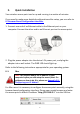
II. Quick Installation Your wireless access point can be up and running in a matter of minutes. If you need to make more detailed configurations after setup, you can refer to III. Browser Based Configuration Interface. 1. Connect one end of an Ethernet cable to the Ethernet port on your computer. Connect the other end to an Ethernet port on the access point. 2. Plug the power adapter into the device’s 5V power port, and plug the adapter into a wall socket. The PWR LED should light up.
You will then be prompted to enter the device’s username and password. The default username is admin and the default password is 1234. From here, you will see the browser based configuration interface home screen.
Select “Basic Settings” from the menu on the left side of the screen. “Basic Settings” allows you to set the mode of the access point and configure the settings accordingly.
that will help you to extend your Wi-Fi network. The device acts as a client and AP at the same time. It its client function to connect to a root AP, and uses its AP function to service wireless clients within its coverage. Please refer to the appropriate chapter of the user manual for your desired operating mode: - III-2-1. III-2-2. III-2-3. III-2-4. III-2-5. III-2-6.
II-2. Windows 1. Windows users can run the setup wizard on the included CD. Insert the Edimax CD into your computer’s CD drive. When the AutoPlay screen appears, select “Run Autorun.exe.” Note: If a popup window appears asking “Do you want to allow the following program to make changes to this computer”, please click “Yes” to continue. 3. Click on “Setup Utility” in the main menu, then select “English” to continue. 4. The setup wizard will search for the access point.
6. The setup wizard will then show the access point’s IP information. The default IP is 192.168.2.1. Click “Next” to continue. Note: Please do not select “Automatically assign an IP address from your network” unless you are performing more advanced setup. For first-time installation, please use the default IP address. 7. You now have the option of selecting which mode you want to use.
II-2-1. Access Point Mode 1. Select Access Point Mode and click “Next”. 2. You will be prompted to set the SSID of this access point. The SSID will be the name of the access point when you connect to it wirelessly. The default SSID is Edimax AP. This page also offers the option to change the password used to access the device’s configuration settings. For first time setup, please simply click “Next” without changing anything. 3. You will now be prompted to set up a wireless encryption password.
5. The device will save your settings, then reboot. Please do not disconnect or turn off the device during this process. 6. After the device reboots, you will see a final congratulation screen. Click “Finish” to complete the setup.
II-2-2. AP Client Mode 1. Select AP Client Mode and click “Next”. 2. You will have the option to change the password used to access the device’s configuration settings. For first time setup, please simply click “Next” without changing anything. 3. The device will search for nearby wireless networks to connect to. If you cannot find the access point you wish to connect to, click “Scan” to refresh the list of wireless networks.
6. The device will save your settings, then reboot. Please do not disconnect or turn off the device during this process. 7. After the device reboots, you will see a final congratulation screen. Click “Finish” to complete the setup.
II-2-3. Repeater Mode (Wi-Fi Extender) 1. Select Repeater Mode and click “Next”. 2. You will be prompted to set the SSID of this device. The SSID will be the name of the device when you connect to it wirelessly. The default SSID is Edimax AP, you are option to change it to the same SSID as your current wireless network. This page also offers the option to change the password used to access the device’s configuration settings. 3. The device will search for nearby wireless networks to connect to.
6. The device will save your settings, then reboot. Please do not disconnect or turn off the device during this process. 7. After the device reboots, you will see a final congratulation screen. Click “Finish” to complete the setup.
II-6. Hardware Installation After configuring your device, you can install it in its final location. Access Point Mode Connect one port of the device to your router or xDSL modem. You can now connect to the device through a wired connection by connecting your computer to it with an Ethernet cable, or connect to the device wirelessly by searching and connecting to the device name you set up.
III. Browser Based Configuration Interface Once you have setup the access point in its desired operating mode as detailed in II. Quick Installation, you can further configure the settings of the access point anytime using the browser based configuration interface. Note: You may need to modify the IP address of your PC or Macintosh before you can access the browser based configuration interface. This is because the access point’s default IP address 192.168.2.
You will then be prompted to enter the device’s username and password. The default username is admin and the default password is 1234.
From here, you will see the browser based configuration interface home screen.
III-1. Home The Home page displays 11 categories in the left panel which you can select: - III-1. III-2. III-3. III-4. III-5. III-6. III-7. III-8. III-9. III-10. III-11. Home Basic Settings WPS Setting Advanced Settings Security Radius Server MAC Filtering System Utility Configuration Tool Upgrade Reset At the top of the screen on the right side there is a drop down menu to change the language of the browser based configuration interface.
System Uptime Hardware Version Runtime Code Version Displays the total time the access point has been operational since it was last switched on. Displays hardware version. This information is helpful if you experience problems with your access point and need technical support. Displays current firmware version. This information is useful when performing a firmware upgrade. Wireless Configuration Mode Displays the current operating mode of the access point.
LAN Configuration IP Address Subnet Mask Default Gateway MAC Address III-2. Displays the IP address of the access point. Displays the subnet mask of the IP address. Displays the IP address of the default gateway. Displays the MAC address of the Access Point. Basic Settings “Basic Settings” allows you to set the access point to any of several different modes and configure the settings accordingly.
points can be connected in this mode. This mode is similar to “AP Bridge to Multi-Point”, but the device is not in bridge-dedicated mode, and will be able to accept wireless clients while the device is working as a wireless bridge. The device will act as a wireless range extender. Acting as both a client and access point at the same time, client function will connect to a root AP, while access point function will service wireless clients within range.
MAIN ESSID Channel Number Associated Clients combinations of each. Only wireless clients of the same band or bands as you select will be able to connect. Specify an ESSID (the name used to identify the access point) of up to up to 32 alphanumerical characters. Please note that the ESSID is case sensitive. Select a channel number for the access point. Where possible, select a channel number which is not already in use by another access point/router.
MAIN ESSID Site Survey Specify an ESSID (the name used to identify the access point) of up to up to 32 alphanumerical characters. Please note that the ESSID is case sensitive. Click the “Select Site Survey” button to display the “Wireless Site Survey Table” which shows all available Wi-Fi networks. Select which network the access point will connect to (see below). Click “APPLY” to save changes.
button. III-2-3. AP Bridge-Point to Point Mode In AP bridge-point to point mode, the access point connects to another wireless access point in the same mode, and all connected Ethernet clients of both devices are connected together. This allows two physically isolated networks to communicate with each other. Note: The access point will not accept regular wireless clients in this mode. Band Channel Number MAC address 1 Set Security Select the wireless band you wish to use for the access point: 802.
or click “APPLY” to restart the system and make the changes take effect. III-2-4. AP Bridge-Point to Multi-Point Mode In AP bridge-point to multi-point mode the access point can connect to up to four other wireless access points also using the same mode, and all connected Ethernet clients of all access points will be connected together. This allows several physically isolated networks to communicate with each other. Note: The access point will not accept regular wireless clients in this mode.
Click “CONTINUE” to save the changes and continue configuring other settings, or click “APPLY” to restart the system and make the changes take effect. III-2-5. AP Bridge-WDS In this mode, the access point can connect to up to four other wireless access points also using the same mode, and all connected Ethernet clients of all access points will be connected together. This allows several physically isolated networks to communicate with each other.
Associated Clients MAC address 1-4 Set Security channel number must be the same as the other access points you wish to connect to. Click the “Show Active Clients” button and a new window will appear which displays information about wireless clients connected to this access point. Click the “Refresh” button in the new window to refresh the list. Enter the MAC addresses of the wireless access points you wish to connect to. Click “Set Security” to select an encryption mode for this wireless link.
Band MAIN SSID Channel Number Associated Clients Root AP SSID Select Site Survey Select the wireless band you wish to use for the access point: 802.11b, 802.11g, 802.11n or selected combinations of each. Only wireless devices of the same band or bands as you select will be able to connect. Specify an ESSID (the name used to identify the access point) of up to up to 32 alphanumerical characters. Please note that the ESSID is case sensitive. Select a channel number for the access point.
III-3. WPS Setting WPS (Wi-Fi Protected Setup) is a simple way to establish connections between WPS compatible devices. WPS devices feature a WPS function which can be activated by pushing a WPS button on the device or from within the device’s firmware/configuration interface. When WPS is activated in the correct manner and at the correct time for two compatible devices, they will automatically connect.
WPS Status Self PIN Code Displays “Configured” or “unConfigured” depending on whether WPS Settings for the access point have been configured or not, either manually or using the WPS button. This is the WPS PIN code of the wireless access point for use with other WPS-enabled wireless devices. SSID Displays the SSID (ESSID) of this access point. Authentication Mode The wireless security authentication mode of this access point will be shown here.
III-4. Advanced Settings In “Advanced Setting” you can configure the advanced features of the access point. Please do not modify these settings unless you know what effect the changes will have on your access point; advanced settings are for experienced users only. Note: Changing these settings can adversely affect the performance of your access point. Fragment Threshold Set the Fragment threshold of the wireless radio.
RTS Threshold Beacon Interval DTIM Period Data Rate N Data Rate Channel Width Preamble Type Broadcast ESSID WMM CTS Protect TX Power you are familiar with this setting. Set the RTS threshold of the wireless radio. The default value is 2347 - please do not modify unless you are familiar with this setting. Set the beacon interval of the wireless radio. The default value is 100 - please do not modify unless you are familiar with this setting. Set the DTIM period of wireless radio.
may not require 100% output power. Setting a lower power output can enhance security since potentially malicious/unknown users in distant areas will not be able to access your signal. Click “APPLY” to save changes. The following message will appear: Click “CONTINUE” to save the changes and continue configuring other settings, or click “APPLY” to restart the system and make the changes take effect.
III-5. Security The access point provides a variety of wireless security options (wireless data encryption). When data is encrypted, information transmitted wirelessly cannot be read by anyone who does not know the encryption key. Note: It is important to configure security to prevent intruders from accessing your local network and causing damage to computers and servers. Use complicated, hard-to-guess security keys which include combinations of letters and numbers – and change your security key regularly.
III-5-1. Disable When you select “Disable”, wireless encryption for the network is disabled. This means anyone who knows the device’s SSID can connect to it, and is not recommended. Enable 802.1x Authentication Check this box to enable 802.1x user authentication. See III-5-2. 802.1x Authentication. Click “APPLY” to save changes.
RADIUS Server Port RADIUS Server Password Enter the port number of the RADIUS authentication server here. Default value is 1812. Enter the password of the RADIUS authentication server here. Click “APPLY” to save changes. The following message will appear: Click “CONTINUE” to save the changes and continue configuring other settings, or click “APPLY” to restart the system and make the changes take effect. III-5-3. WEP WEP (Wired Equivalent Privacy) is a basic encryption type.
Key Format Default Tx Key Encryption Key 1 to 4 Enable 802.1x Authentication 128-bit. Using “128-bit” is safer than “64-bit”, but will reduce some data transfer performance. Select a key format: ASCII or Hex. The key length will also be displayed here - ASCII and Hex keys vary in length according to “Key Length” (above)”. You can set up to four sets of WEP keys, and you can decide which key is used the default. If you are unsure, leave the value as the default “Key 1”.
Suite AES is safer than TKIP, but not supported by all wireless clients. Please make sure your wireless client supports your selection. WPA2(AES) is recommended, or WPA2 Mixed if your client does not support AES. Select the pre-shared key format from “Passphrase” (8 to 63 alphanumerical characters) or “Hex (64 characters 0 to 9 and a to f.) Please enter the key according to the key format you selected above. For security reasons, it’s best to use a complex, hard-to-guess key.
Use internal MD5/PEAP RADIUS Server RADIUS Server IP address RADIUS Server Port RADIUS Server Password clients. Please make sure your wireless client supports your selection. WPA2(AES) is recommended, or WPA2 Mixed if your client does not support AES. Check the box to use an internal MD5/PEAP RADIUS Server. Enter the IP address of the RADIUS authentication server here. Enter the port number of the RADIUS authentication server here. Default value is 1812.
III-6. Radius Server Radius server settings can be configured on this page. A Radius server provides user-based authentication to improve security and offer wireless client control – users can be authenticated before gaining access to a network. The access point’s internal radius server only supports 96 users and 16 IP addresses – for more users and/or IP addresses please use an external radius server.
Enable Radius Server Username Password Re-Type Password Configure Check the box to enable the Radius server. Enter a username for a Radius user profile. Enter a password for a Radius user profile. Confirm the password. Select “Add” to add the user profile – all user profiles will be displayed underneath once they have been added. Select “Reset” to clear all fields. Select Check this box to select Radius user(s). Delete Selected Click this button to delete selected Radius user(s).
III-7. MAC Filtering The MAC filtering feature allows you to define a list of wireless devices permitted to connect to this access point, identified by their unique MAC address. When devices not on the list of MAC addresses attempt to connect to this access point, they will be denied. Select SSID SSID choice Select which SSID to configure MAC address filtering. MAC Address Filtering Table Select Displays MAC addresses which have been added to the list of permitted devices.
Delete Selected Delete All Reset Click this button to delete selected MAC address(es). Delete all MAC addresses in the table. Uncheck all selected MAC address entries. Enable Wireless Access Control MAC address Check this box to enable MAC address filtering. Comment Add Clear Enter a MAC address permitted to connect to the access point. Only enter characters 0 to 9 or a to f.
III-8. System Utility In “System Utility” you can configure basic system and administrative parameters. III-8-1. Password Settings You can change the password used to login to the browser-based configuration interface here. It is advised to do so for security purposes. Password Settings Current Password New Password Re-Enter Password Enter your current password. The default password is 1234. Enter your desired new password here.
Click “APPLY” to save changes. The following message will appear: Click “CONTINUE” to save the changes and continue configuring other settings, or click “APPLY” to restart the system and make the changes take effect. III-8-2. Management IP You can modify the IP address of the access point, enabling it to become a part of your local area network. To do so, input the IP address, subnet mask and gateway address into the corresponding fields.
not be able to connect to the browser-based configuration interface in the future. Note: To reset the IP address back to its default value of 192.168.2.1, press and hold the WPS/Reset button on the access point for 10 seconds. Be aware that doing so restores all settings and passwords back to factory defaults. Click “APPLY” to save changes.
Domain Name Server IP Start IP End IP Domain Name Lease Time Input the IP address of the domain name server (DNS). Input the start address of the IP range. Input the end address of the IP range. Input the domain name for your network (optional). Choose a lease time (the duration that every computer can keep a specific IP address) of every IP address assigned by the access point. Click “APPLY” to save changes.
III-9. Configuration Tool The access point’s configuration tool enables you to back up the current settings, restore the settings to a previously backed up version or reset the access point back to its original factory settings. Backup Settings Restore Settings Restore to Factory Defaults Click “Save” to save the current settings on your computer as a .bin file. The default filename is config.bin.
button is located on the front panel of the device. III-10. Upgrade The access point’s upgrade feature allows you to update the system firmware to a more recent version. You can download the latest firmware from the Edimax website. Selecting “Upgrade” from the menu on the left side will bring you to the following screen. Note: Do not turn off or disconnect the access point during a firmware upgrade, as this could damage the device.
Refresh your browser to return to the “Status and Information” homepage of the browser based configuration device. III-11. Reset If the access point malfunctions or is not responding, then it is recommended that you reset the device. This feature is useful if the location of the access point is not convenient. Note: If the access point is still not responding after a reset, then switch off the device by disconnecting the power supply and wait for 10 seconds before reconnecting the power.
Windows: Mac: Click “OK” to continue, or “Cancel” to abort. You will see a warning that it may take a while for the access point to reset. Note: Do not turn off the Access point during the reset process.
Windows: Mac: Please click “OK” to start the reset process. You will see the following screen while the system resets, the timer will count down from 30 seconds. When the timer reaches zero and the reset is complete, please click “OK”. You will return to the “Reset” page of the browser based configuration interface.
IV. IV-1. APPENDIX Configuring your IP address Before you use this access point, you may need to modify the IP address of your PC or Macintosh. The procedure for doing so varies across different operating systems; please follow the appropriate guide: - IV-1-1. IV-1-2. IV-1-3. IV-1-4. IV-1-5. Windows XP Windows Vista Windows 7 Windows 8 Mac OS This is since the access point’s default IP address 192.168.2.
The “Local Area Connection Status” window will appear, click “Properties”. 2. Select “Use the following IP address”, and input the following values: Note: Please note your existing setting before changing it. After you have finished using the browser based configuration interface, change this setting back to its original value. IP address: 192.168.2.10 Subnet Mask: 255.255.255.0 Click ‘OK’ when finished.
IV-1-2. Windows Vista 1. Click the “Start” button, located in the lower-left corner of your computer, and then click “Control Panel”. Click “View Network Status and Tasks” and then click “Manage Network Connections”. Right-click “Local Area Network”, and select “Properties”. The “Local Area Connection Properties” window will appear, select “Internet Protocol Version 4 (TCP / IPv4)”, and click “Properties”.
2. Select “Use the following IP address”, and input the following values: IP address: 192.168.2.10 Subnet Mask: 255.255.255.0 Note: Please note your existing setting before changing it. After you have finished using the browser based configuration interface, you can change this setting back to its original value. Click ‘OK’ when finished. IV-1-3. Windows 7 1. Click the “Start” button, located in the lower-left corner of your computer, and then click “Control Panel”.
1. Under “Network and Internet” click “View network status and tasks”. 2. Click “Local Area Connection”.
3. Click “Properties”. 4. Select “Internet Protocol Version 4 (TCP/IPv6) and then click “Properties”.
5. Select “Use the following IP address”, and input the following values: Note: Please note your existing setting before changing it. After you have finished using the browser based configuration interface, you can change this setting back to its original value. IP address: 192.168.2.10 Subnet Mask: 255.255.255.0 Click ‘OK’ when finished.
IV-1-4. Windows 8 1. From the Windows 8 Start screen, you need to switch to desktop mode. Move your curser to the bottom left of the screen and click. 2. In desktop mode, click the File Explorer icon in the bottom left of the screen, as shown below.
3. Right click “Network” and then select “Properties”. 4. In the window that opens, select “Change adapter settings” from the left side.
5. Choose your connection and right click, then select “Properties”. 6. Select “Internet Protocol Version 4 (TCP/IPv4) and then click “Properties”.
7. Select “Use the following IP address”, then input the following values: Note: Please note your existing setting before changing it. After you have finished using the browser based configuration interface, you can change this setting back to its original value. IP address: 192.168.2.10 Subnet Mask: 255.255.255.0 Click ‘OK’ when finished.
IV-1-5. Mac OS 1. Have your Macintosh computer operate as usual, and click on “System Preferences”. 2. In System Preferences, click on “Network”. 3. Here you will see all of your network connections. Network Preferences will now display an Ethernet adapter, as shown below. The status of “Ethernet” should be “Connected”.
4. Click on “Ethernet” in the left panel and then click the drop down arrow for the menu labeled “Configure IPv4” in the right panel. From the drop down menu, select “Manually”. 5. In the panel on the right side, enter IP address 192.168.2.10 and subnet mask 255.255.255.0. Click on “Apply”.
6. In the left sidebar, “Ethernet” should now display “Connected” as shown below. In the right panel, you should see the IP address 192.168.2.10 and subnet mask 255.255.255.0.
IV-2. How to Find your Network Security Key To find your network security key, please follow the instructions appropriate for your operating system. Note: If you are using Windows XP or earlier, please contact your ISP or router manufacturer to find your network security key. IV-2-1. Windows 7 & Windows Vista 1. Open “Control Panel” and click on “Network and Internet” in the top menu. 2. Click on “View network status and tasks” which is under the heading “Network and Sharing Center”. 3.
4. You should see the profile of your Wi-Fi network in the list. Right click on your Wi-Fi network and then click on “Properties”. 5. Click on the “Security” tab, and then check the box labeled “Show characters”. This will show your network security key. Click the “Cancel” button to close the window.
IV-2-2. Windows 8 1. From the Windows 8 Start screen, you need to switch to desktop mode. Move your curser to the bottom left of the screen and click. 2. In desktop mode, click the network icon in the bottom right corner. 3. Select your Wi-Fi connection from the list and right click.
connection properties”. 4. In the window that opens, click the “Security” tab and check the box labeled “Show characters”. Your network security key will be displayed in the field “Network security key”.
IV-2-3. Mac 1. Open a new Finder window, and select “Applications” from the menu on the left side. Open the folder labeled “Utilities” and then open the application “Keychain Access”. 2. Select “Passwords” from the sub-menu labeled “Category” on the left side, as shown below. Then search the list in the main panel for the SSID of your network. In this example, the SSID is “EdimaxWireless” – though your SSID will be unique to your network.
3. Double click the SSID of your network and you will see the following window. 4. Check the box labeled “Show password” and you will be asked to enter your administrative password, which you use to log into your Mac. Enter your password and click “Allow”.
Your network security password will now be displayed in the field next to the box labeled “Show password”. In the example below, the network security password is “edimax1234”. Please make a note of your network security password.
IV-3. Troubleshooting If you are experiencing problems with your access point, please refer to this troubleshooting guide before contacting your dealer of purchase for help. Scenario My access point can’t locate a wireless access point/wireless device when using the “Site Survey” function. Solution a. Click “Rescan” several more times and see if the wireless access point/device appears. b. Adjust the position of the access point, or move closer to a known wireless access point. c.
client. configuration interface) is “Enabled” or “Disabled”. If “Disabled” you need to input the ESSID into your wireless client manually. b. Try moving closer to the access point File transfers are slow or a. Try to move closer to where the wireless access frequently interrupted. point is located. b. Try again later. Your local network may be experiencing technical difficulties or very high usage. c. Change channel number. I can’t log onto the a. Password is case-sensitive.
computers on your home network is the location of the DNS server your ISP has assigned to you. DSL Modem: DSL stands for Digital Subscriber Line. A DSL modem uses your existing phone lines to transmit data at high speeds. Ethernet: A standard for computer networks. Ethernet networks are connected by special cables and hubs, and move data around at up to 10/100 million bits per second (Mbps).
LAN: Local Area Network. A LAN is a group of computers and devices connected together in a relatively small area (such as a house or an office). Your home network is considered a LAN. MAC Address: MAC stands for Media Access Control. A MAC address is the hardware address of a device connected to a network. The MAC address is a unique identifier for a device with an Ethernet interface.
so that when they interface with each other based on such a protocol, the interpretation of their behavior is well defined and can be made objectively, without confusion or misunderstanding. Access point: A access point is an intelligent network device that forwards packets between different networks based on network layer address information such as IP addresses. Subnet Mask: A subnet mask, which may be a part of the TCP/IP information provided by your ISP, is a set of four numbers (e.g. 255.255.255.
French Office Tel: +33-160535680 Fax: +33-160535689 Support: support@edimax.fr German Office Tel: +49-215488-77334 Fax: +49-215488-77339 Support: support@edimax-de.eu Poland Office Tel: +48-22-6079480 Fax: +48-22-6079481 Support: support@edimax.pl Romania Office Tel: +40-31-4250126 Fax: +40-31-4250125 Support: support@edimax.ro Russia Office Tel: +7-499-7266678 Email: sales@edimax.ru Support: support@edimax.
Australia Office Tel: +61-3-95431888 Fax: +61-3-98992746 Tech Support: 1300 540 833 Email: sales@edimax-au.com Support: support@edimax-au.com China Office Tel: +8610-82665815 Fax: +8610-82665795 Support: service@edimax.com.cn Hong Kong Office Tel: +852-2169 6311 Fax: +852-2169 6300 Support: service@edimax.com.
Malaysia - Kuala Lumpur Authorized Service Centre Technical Hotline: 03 2052 4288; 03 9130 7728 (11am ~ 8pm, Monday ~ Friday except national holidays) Email: sales@edimax.com.sg Support: support@edimax.com.sg Indonesia - Jakarta Authorized Service Centre Sales & Technical Hotline: 021 70777 629 (9am ~ 6pm, Monday ~ Sunday except national holidays) Support: idsupport@edimax.com.