M-JPEG Internet Camera IC-1500Wg / IC-1500 User Manual Version 1.
Contents 1. 2. 3. 4. 5. 6. 7. 8. Introduction ................................................................................................................................. 1 Package Content ........................................................................................................................ 1 System Requirement ................................................................................................................ 1 Hardware Installation ...................................
1. Introduction Thank you for choosing the Internet Camera. This Internet Camera sends live video through 10/100Mbps wired network to a web browser or camera viewer across Internet anywhere in the world! This compact, self-contained unit lets you keep an eye on your home, your kids, and your workplace—whatever’s important to you. How does the Camera do all of this? Unlike standard “web cams” that require an attached PC, the Internet Camera can connect directly to a network.
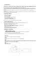
Camera Ports The Camera features three ports and a Reset button. y Power The Power port is where you can connect the power adapter. y LAN The LAN port is where you can connect the Ethernet network cable. y WLAN (for IC-1500Wg only) (Antenna Connector) This round connection is standard Reverse SMA connector where any antennas with Reverse SMA connector can connect to the Internet Camera.. y Reset 1.
. Software Installation Follow the simple steps below to run the Install Wizard to guide you quickly through the Installation process. The following installation is implemented in Windows XP. The installation procedures in Windows 98SE/Me/2000/Server 2003 are similar. 1. Insert the CD shipped along with the Internet Camera into your CD-ROM drive. The “Autorun.exe” program should be executed automatically. If not, run “Autorun.exe” manually from “Autorun” folder in the CD. 2.
5. Click “Install” to start installing the program. 6. The system will install the program automatically.
. Click “Finish” to complete the software installation. 8. When the installation is completed. The system will auto run ”Administrator Utility“. On the Internet Camera first page, the cameras found in the network are listed in the left window. Choose the one you want to configure and click “Setting Wizard” to proceed. N IC-1500 “N” means the camera is new and not configured. 9. Please enter the default password “1234” and click “OK” to login to the IP setup page. 10.
11. This wizard will pop up a window to ask you if you want to run the “Camera Viewer” and see the video of the Camera immediately. Select “OK” to run “Camera Viewer”. 12. The “Camera Viewer” will show the video automatically. Congratulations, you can use the camera through the network to view the video from now on.
6. Using the Administrator Utility The Administrator Utility allows users to search and setup the cameras located within the Intranet or on the Internet. From the utility, users can view all the information of the selected camera; furthermore, it provides a setting wizard, which can guide users to add the camera to the network easily and promptly. There are two ways to run the Administrator Utility as follows. 1. Click “Start”, select “Programs\IP Camera\Admin Utility” to run the utility. 2.
LAN Auto Discover Click the button will search the camera within the network automatically. The list shows the camera name and the setup status of the camera. Camera List It means the camera is in the default setting. It means the camera is configured before. Internet Add Click “Add” will appear a window for you to enter the IP Address of the camera on the Internet. Delete Click “Delete” to delete the camera from the list. The list shows the camera name and the connect status of the camera.
6.1.3. Network Setting Network Setting Internet The default camera name is “IC1500WG”. It is recommended to name a meaningful name for Camera Name the camera. IP Address Enter an unused IP Address within the IP address range used on your LAN. If the IP Address of your LAN is from the 192.168.2.1 to 192.168.2.254, you can set an unused IP Address from the range for the camera, for example: 192.168.2.250. Subnet Mask The Subnet Mask field must match the subnet setting on your LAN. For example: 255.255.
6.1.4. E-Mail Setting E-Mail Setting Recipient E-Mail This camera supports “Snap Shot” and “Motion Detection” functions. You can snapshot a Address picture and send the picture by E-Mail. Enter the E-Mail Account for receiving the picture. SMTP Server Enter the SMTP Server for the E-Mail sending. Sender E-Mail Address Specified the e-mail address of the e-mail sender. Authentication Enable or Disable the SMTP Authentication function Username When Authentication is enabled, input the SMTP Username.
6.1.5. FTP Settings FTP Settings FTP Server FTP Port This camera supports “Motion Detection” functions. When Motion Detection event occurred, you can record the live video to FTP server. Enter the FTP address for receiving the video. Enter the port of the FTP server. User Name Specify the user account of ftp server. Password Specify the Password of your ftp account. Remote Folder Specify the folder of the ftp site that you want to store the video. Password Passive Mode 6.1.6.
Date / Time Settings Set Date/Time manually 6.1.7. Set the current Date and Time. NTP Server Synchronize the Date and Time with NTP server. Time Zone Select the time zone that your camera put on. NTP Server Specify the IP Address of the NTP Server. Resolution Resolution Resolution 6.1.8. Select the desired video resolution format. Larger resolution requires more bandwidth. 640 x 480 is “VGA” format. 320 x 240 is “CIF” format.
Advanced Setting UPnP When the UPnP function is enabled, the camera can be detected by UPnP compliant system such as Windows XP. The camera will be displayed in the Neighborhood of Windows XP, so you can directly click the camera to view the video through web browser. DDNS Many internet connections use a "Dynamic IP address", where the Internet IP address is allocated dynamically whenever the Internet connection is established.
6.1.10. Tools Tools Firmware Version Display current firmware version. Firmware Update You can upgrade camera’s firmware via this function. Press this button and select the correct firmware to upgrade. Reset to Default If you want to reset the camera, click this button. The default settings of the camera are as follows. Camera Name: “IPCamera” IP Address: “192.168.2.3” Subnet Mask: 255.255.255.
6.1.11. About About Administrator Utility Version Display current Administrator Utility Version. 6.1.12. Setting Wizard When you click the “Setting Wizard”, a screen will pop up for you to enter the “Administrator Name” and “Password”. The default value is as follows. Name: “Admin” Password: “1234” If the name and password you enter are correct, you can start to setup the camera.
Setting Wizard Internet Camera Name IP Address The default camera name is “IC1500Wg”. It is recommended to enter a meaningful name for the camera. The wizard will auto setup an available IP Address to the camera. For example: if the IP address of the network is 192.168.2.x, the wizard will search an unused IP Address from 192.168.2.250 to 192.168.2.0 and assign the camera an available IP Address. You are allowed to enter another IP Address to change the setting.
7. Using the Camera Viewer The Camera Viewer Utility allows users to view video from up to four cameras. It also allows users to manual/schedule record video and playback the recording file. The status of camera viewing such as frame rate, video received, and etc. are also recorded in time. There are three ways to run the Camera Viewer Utility as follows. 1. Click “Start”, select “Programs\IP Camera\Camera Viewer” to run the utility. 2. 3. Click the “IP Camera Viewer” icon to run the utility.
7.1.3. Camera Status There is a status bar shown different color to indicate the status of each Internet Camera. Camera Status It means that there is no camera set to connect. Yellow 7.1.4. Blue It means that the camera is connected and playing the live video. Pink It means that the camera is not connected now. Red It means that the camera is recording.
7.1.5. Video Recording This utility allows you record the video in AVI format files. There are two ways of video recording – Manual Recording and Schedule Recording. Manual Recording You can manually record the video stream into an assigned video file. Click “Record”, then the viewer utility will start to record the video stream. You can assign the path in the setting dialog. If you want to stop recording, click “Stop”.
7.1.7. View Four Cameras Simultaneously Click the four division button 7.1.8. can view the 4 cameras simultaneously in a four-division window. When Viewer Utility Setting Click the “Setting” , then the setting window of the Internet Camera will pop up. Note: When you want to change the settings such as IP Address, Video Port, etc. in the “Setting” option, you must disconnect the Internet Camera first by clicking the “Stop”.
7.1.9. Setting Setting Name It is not required to fill the camera name for connecting camera. It is for users to identify the camera. IP Address IP address/Domain name of the Internet Camera. Video Port The number of service port used by the Internet Camera. Model Select “Internet Camera” (This camera only supports MJPEG). Username The user name for login into the Internet Camera. By default, the user name is “Admin”. Password The password for login into the Internet Camera.
7.1.10. Recording You can setup schedule for the recording here. This utility will record the video stream in the assigned file folder according to the schedule automatically. The recorded video files are AVI format. Note: 1. The utility will only start to record the video stream when this utility is running and is successfully connecting to the Internet camera in the beginning of the schedule. 2. The schedule setting of one-time or weekly schedule should not overlap, or the recording will fail.
Weekly Schedule Schedule Cycle Recording Select this item to enable cycle recording. When the Cycle Recording is enabled and the storage usage has already reached the maximum reserved storage space, the utility will automatically delete the oldest recorded video file and use the space to store the newly recorded video stream. One-Time Schedule You can assign a range of time and the utility will automatically record the video stream only during the period of time.
Status Connected Stream Started At Time Elapsed It displays “Yes” when the utility is connecting to the Internet Camera and displays “No” when the utility is not connecting to the Internet Camera. The beginning time of the current connection session between the utility and the Internet Camera. The elapsed time of the current connection session between the utility and the Internet Camera.
7.1.13. About About Camera Viewer Utility Version Display current Camera Viewer Utility Version. 7.1.14. Playback Click the “Open File” and a “Load File” window will be popped up. Select the file that you want to play. The viewer will start to play the selected video file.
Playing Control Play Pause Stop Forward 7.1.15. When the video playback is in Stop state, just click “Play” and the viewer will play the video file from the beginning point. When the video playback is in Pause state, just click “Play” and the viewer will play the video file from the current pause point. When the viewer is playing with fast speed, just click “Play” to let the viewer play with the normal speed. When the recorded video is playing, you can click “Pause” to freeze the playback.
8. Web Connection and Setup You can use the Web browser to connect the camera for viewing or setting. Open the web browser and enter the IP Address of the camera to establish a connection. The default IP Address of the camera is “192.168.2.3”. When the welcome screen appears, enter the “Admin Name” and “Password”. The default values are: Admin Name: “admin” & Password: “1234” When the camera is connected, the browser will take you to the live video page.
The menu options for the web control screen are as follows. z Camera – View live video and adjust the video format from the menu. z LAN – Setup the camera LAN port functions in the menu. z WLAN ( for IC-1500Wg only) – Setup the camera WLAN port functions in the menu. z E-Mail & FTP – Setup the E-Mail client and FTP client in the menu. z Motion Detection – Configure the Motion Detection Actions here. z System – Setup System utilities and settings in this menu.
8.1.2. LAN Setting LAN Network Type IP Address Subnet Mask Gateway DNS Server This camera can obtain IP via DHCP protocol or specified static IP Address to it.. Enter an unused IP Address within the IP address range used on your LAN. If the IP Address of your LAN is from the 192.168.2.0 to 192.168.2.250, you can set an unused IP Address from the range for the camera, for example: 192.168.2.250. The Subnet Mask field must match the subnet setting on your LAN. For example: 255.255.255.0.
8.1.3. WLAN ( for IC-1500Wg only) Wireless Setting Wireless connection Enable or disable the wireless function of the Internet Camera. By default, the function is disabled. Network Type Infrastructure – This operation mode requires the presence of a Wireless LAN Access Point or Router. All communication is done via the Access Point or Router. Ad-Hoc – Select this mode if you want to connect to another wireless stations in the Wireless LAN network without through an Access Point or Router.
Key1 ~ Key4 The WEP keys are used to encrypt data transmitted in the wireless network. Fill the text box by following rules below. 64-bit – Input 10-digit Hex values (in the “A-F”, “a-f” and “0-9” range) or 5-digit ASCII characters (including “a-z” and “0-9”) as the encryption keys. For example: “0123456aef“ or “test1”. 128-bit – Input 26-digit Hex values (in the “A-F”, “a-f” and “0-9” range) or 13-digit ASCII characters (including “a-z” and “0-9”) as the encryption keys.
8.1.5. Motion Detection The “Motion Detection” allows users to setup the behavior of motion detection feature. Motion Detection Motion Detection Enable Next Event Detected Interval Enable or Disable the Motion Detection Function. Setup the interval between two events. For example, if you setup the interval to 5 seconds, the next event will start after this event finished + 5 seconds. Recording Time Setup how long of video will be record when motion detection event occurred.
8.1.6. System The “System” allows users to setup the camera’s parameters, like camera name, data/time setting. And also provide firmware upgrade and reset tools at this page. System Camera Name The default camera name is “IC1500 or IC1500Wg”. It is recommended to name a meaningful name for the camera. Login Name Setup your administrator account’s login name. Default name is “admin” Password Enter up to 4 digits password for the new user account.
8.1.7. Status The “Status” shows the current firmware version, uptime, system time and IP information of this camera. 8.1.8. Users The “Users” allows users to add four user accounts which are able to view video from Camera Viewer and Web Management. These users, unlike Administrator, are not allowed to configure the camera. User 1 / 2 / 3 / 4 User # Enable or Disable the user number #. Login Enter the the login name to the camera.
9. Frequently Asked Questions Q1: What is an Internet Camera? A: The Internet Camera is a standalone system connecting directly to an Ethernet or Fast Ethernet network. It is different from the conventional PC Camera; the Internet Camera is an all-in-one system with built-in CPU and web-based solutions providing a low cost solution that can transmit high quality video images for monitoring.
TCP/UDP connections from remote PC to the Internet Camera. The Router/Gateway should set port forwarding or virtual server for the connections. Please see the illustration as below. Router/Gateway Port Forwarding/Virtual Server Setup Name Setup 1 Setup 2 Setup 3 Setup 4 Protocol TCP TCP UDP UDP Port 80 4321 13364 4322 LAN IP 192.168.2.3 192.168.2.3 192.168.2.3 192.168.2.3 Port Definition Setup 1 It is the port of Web port. You have to configure the protocol to “TCP”.
12. Appendix B Viewing via UPnP in Windows XP When the UPnP function is enabled, the camera can be detected by UPnP compliant system such as Windows XP. The camera will be displayed in the Neighborhood of Windows XP, so you can directly double click the camera or right click the camera and select “Invoke” to view the video through web browser.
4. The “Windows Firewall” screen will be popped up, select “Exceptions” option menu.
5. Enable “UPnP Framework” from the “Programs and Services list” and click “Ok”.