IC-1510 / IC-1510Wg Fast Ethernet / Wireless 802.11b/g Internet Camera User Manual Version: 1.
Contents 1. 2. 3. 4. Introduction .........................................................................................................1 Package Content.................................................................................................1 System Requirement ..........................................................................................1 Hardware Installation..........................................................................................2 4.1. LED and Focusing ..........
7.8.5. About ............................................................................................46 7.9. Playback ..............................................................................................47 7.10. Rotate Video........................................................................................49 8. Web Connection and Setup .............................................................................50 8.1. Camera Setting ........................................................
1. Introduction Thank you for choosing the Internet Camera. This Internet Camera sends live video through 10/100Mbps wired network to a web browser or camera viewer across Internet anywhere in the world! This compact, self-contained unit lets you keep an eye on your home, your kids, and your workplace—whatever’s important to you. How does the Camera do all of this? Unlike standard “web cams” that require an attached PC, the Internet Camera can connect directly to a network.
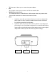
4. Hardware Installation 4.1. LED and Focusing The Camera head and its focus ring allow you to modify the aim and focus of the Camera. To adjust the Camera’s focus, rotate the dark focus ring. There are four LEDs indicating the camera status and networking status. y Power When the camera is power on, the LED will light. y LAN When the Internet Camera is linking to wired network, the LED is lighting. The LED is flashing when video is transmitted or received through wired network.
The Power port is where you can connect the power adapter. y LAN The LAN port is where you can connect the Ethernet network cable. y WLAN (Antenna Connector) This round connection is standard Reverse SMA connector where any antennas with Reverse SMA connector can connect to the Internet Camera. y Reset 1. If problems occur with your Internet Camera, press the reset button with a pencil tip (for less than 2 seconds) and the Internet Camera will re-boot itself, keeping your original configurations. 2.
4.3. Hardware Installation Procedure 1. Unpack the Internet Camera package and verify that all the items listed in the Chapter 2 are provided. 2. Connect the Internet Camera to your network by attached the network cable from the switch/router to the UTP port of the Internet Camera. 3. Connect the power adapter to the Internet Camera and plug the power adapter to power outlet. The Internet Camera will be powered on. When the Internet Camera is ready, the Ready LED will light. 4.
5. Software Installation Follow the simple steps below to run the Install Wizard to guide you quickly through the Installation process. The following installation is implemented in Windows XP. The installation procedures in Windows 2000/Server 2003 are similar. 1. Insert the CD shipped along with the Internet Camera into your CD-ROM drive. The “Autorun.exe” program should be executed automatically. If not, run “Autorun.exe” manually from “Autorun” folder in the CD. 2.
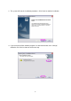
3. The system will start the installation procedures. Click “Next” to continue installation. 4. If you wish to install the software program in an alternate location, click “Change”; otherwise click “Next” to move on to the next step.
5. Click “Install” to start installing the program. 6. The system will install the program automatically.
7. Click “Finish” to complete the software installation. 8. ”Administrator Utility“will be run automatically after installation. On the Internet Camera first page, the cameras found in the network are listed in the left window. Choose the one you want to configure and click “Setting Wizard” to precede. If the camera is new and is not configured with your network, please go to next section “8 Network configurations” to set up the configuration “N” means the camera is new and not configured.
9. Please enter the default password “1234” and click “OK” to login to the IP setup page. 10. Internet Camera is working through the network (TCP/IP Protocol). The IP address and subnet mask setting must be correct, or you cannot access to the camera. The wizard program will detect the IP address status of your network automatically and suggest a free IP address for the Camera. You can accept the suggested value or enter the value manually.
12. The “Camera Viewer” will show the video automatically. Congratulations, you can use the camera through the network to view the video from now on.
6. Using the Administrator Utility The Administrator Utility allows users to search and setup the cameras located within the Intranet or on the Internet. From the utility, users can view all the information of the selected camera; furthermore, it provides a setting wizard, which can guide users to add the camera to the network easily and promptly. There are two ways to run the Administrator Utility as follows. 1. Click “Start”, select “Programs\IP Camera\Admin Utility” to run the utility.
6.1. General Setting LAN Auto Discover Click the button will search the camera within the network. Camera List The list shows the camera name and the setup status of the camera. It means the camera is in the default setting. It means the camera is configured before. Internet Add Click “Add” will appear a window for you to enter the IP Address of the camera on the Internet. Delete Click “Delete” to delete the camera from the list.
the Internet. It means the camera is connected. Information of Camera Camera Information It displays all information of the selected camera. The information includes Firmware Version, Network Information, IP Address, UPnP Setting, DDNS Setting, Resolution and E-mail setting, etc. Camera Setting Detail Setting Click “Detail Setting” to do more setting of the camera such as IP address, Resolution, password and firmware upgrade, etc.
6.2. Detail Setting When you click the “Detail Setting”, a screen will pop up for you to enter the “Administrator Name” and “Password”. The default value is as follows. Name: “Admin” Password: “1234” If the name and password you enter are correct, you can start to setup the camera.
6.2.1. Network Setting Network Setting Internet Camera Name The default camera name is “IC1500WG”. It is recommended to name a meaningful name for the camera. IP Address Enter an unused IP Address within the IP address range used on your LAN. If the IP Address of your LAN is from the 192.168.2.1 to 192.168.2.254, you can set an unused IP Address from the range for the camera, for example: 192.168.2.250. Subnet Mask The Subnet Mask field must match the subnet setting on your LAN. For example: 255.255.
same with the gateway used by the PCs on your LAN. DNS Server DNS Server (Domain Name Server) that translates names to IP addresses. Set the same DNS Server as the PCs on your LAN. Network Setting Video Port The Video Port is used to transmit or receive the video streaming in the network. The default port setting is “4321”. If you want to view the video from the camera, the port setting should be correct. Web Port This camera support web connection, the default web port is 80.
Utility will site survey automatically or you can press “Refresh” button to survey the AP router manually. After site survey procedure, there will show existing AP SSID. Then press “Connect” to connect AP router or press “Add to Profile” to configure the Wireless WEP or WPA encryption.
There are WEP (Open System/Shared Key) ,WPA-PSK,WPA2-PSK and WPANone encryption settings. You can choose one to match AP router wireless settings. After set the profile, Please remove the LAN cable then IP Camera will connect to AP router automatically. LED Status Diagram Wired Setting Environment Wireless Setting Environment You must configure the wireless settings from wired environment. Then you can remove the wired cable and start wireless connection.
6.2.3. E-Mail Setting E-Mail Setting Recipient E-Mail Address This camera supports “SnapShot” and “Motion Detection” functions. You can snapshot a picture and send the picture by E-Mail. Enter the E-Mail Account for receiving the picture. SMTP Server Enter the SMTP Server for the E-Mail sending. Sender E-Mail Address Specified the e-mail address of the e-mail sender. Authentication Enable or Disable the SMTP Authentication function Username When Authentication is enabled, input the SMTP Username.
Send a Test Email Press this button to send a test e-mail to your mailbox. You can use this function to test if your setting is correct. 6.2.4. PPPoE Settings PPPoE Settings Enable/Disable If enable the PPPoE function, IP Camera will use PPPoE for network connection first. The default value is “Disable”. Username Enter the Username of PPPoE connection.
6.2.5. FTP Settings FTP Settings FTP Server This camera supports “Motion Detection” functions. When Motion Detection event occurred, you can record the pictures to FTP server. Enter the FTP address for receiving the pictures. FTP Port Enter the port of the FTP server. User Name Specify the user account of ftp server. Password Specify the Password of your ftp account. Remote Folder Specify the folder of the ftp site that you want to store the video.
6.2.6. Date / Time Settings Date / Time Settings Set Date/Time manually Set the current Date and Time. NTP Server Synchronize the Date and Time with NTP server. Time Zone Select the time zone that your camera put on. NTP Server Specify the IP Address of the NTP Server.
6.2.7. Resolution Resolution Resolution Select the desired video resolution format. Larger resolution requires more bandwidth. 640 x 480 is “VGA” format. 320 x 240 is “CIF” format. 176 x 144 is “QCIF” format.
6.2.8. Advanced Setting Advanced Setting UPnP When the UPnP function is enabled, the camera can be detected by UPnP compliant system such as Windows XP. The camera will be displayed in the Neighborhood of Windows XP, so you can directly click the camera to view the video through web browser. DDNS Many internet connections use a "Dynamic IP address", where the Internet IP address is allocated dynamically whenever the Internet connection is established.
Enable/Disable Enable or disable DDNS function of the camera. Provider Several companies provide DDNS service. This camera supports the service from DynDNS who is one of the DDNS providers. Domain Name The domain name given by DynDNS is “registername.dyndns.com”. Enter the domain name that you register for the camera from DynDNS web site. Account Enter the login name for the DDNS service. Password Enter the password for the DDNS service.
6.2.9. Users Users Administrator Setting the password of Administrator account Current Password Enter the current password of the camera. New Password Enter the new password you want to use for the camera. Confirm New Password Retype the new password to confirm the setting. User Setting the user account and password. Your camera can support 4 user account.
6.2.10. Tools Tools Firmware Version Display current firmware version. Firmware Update You can upgrade camera’s firmware via this function. Press this button and select the correct firmware to upgrade. Reset to Default If you want to reset the camera, click this button. The default settings of the camera are as follows. Camera Name: “IC-XXXXXX” IP Address: “192.168.2.3” Subnet Mask: 255.255.255.
Video Port: “4321” Web Port: “80” 6.2.11. About About Administrator Utility Display current Administrator Utility Version.
6.3. Setting Wizard When you click the “Setting Wizard”, a screen will pop up for you to enter the “Administrator Name” and “Password”. The default value is as follows. Name: “Admin” Password: “1234” If the name and password you enter are correct, you can start to setup the camera. Setting Wizard Internet Camera Name The default camera name is “IC1500Wg”. It is recommended to enter a meaningful name for the camera. IP Address The wizard will auto setup an available IP Address to the camera.
192.168.2.250 and assign the camera an available IP Address. You are allowed to enter another IP Address to change the setting. Subnet Mask The wizard will auto search the Subnet Mask setting of the network and set the camera in the same Subnet Mask. You can enter another Subnet Mask to change the setting. Gateway The wizard will auto search the Gateway setting of the network and set the camera to use the same Gateway. You can enter another Gateway to change the setting.
7. Using the Camera Viewer The Camera Viewer Utility allows users to view video up to four cameras. It also allows users to manual/schedule recording video and playback the video file. The status of camera viewing such as frame rate, video received, and etc. are also recorded in time. There are three ways to run the Camera Viewer Utility as follows. 1. Click “Start”, select “Programs\IP Camera\Camera Viewer” to run the utility. to run the utility. 2. Double click the “IP Camera Viewer” icon 3.
7.2.
Camera Buttons Camera Click one of these four cameras will connect to the selected camera that you want to view and configure. If you want to remove the camera from the viewer, please right click the icon and select “Reset Camera x”. If you want to configure the camera, please right click the icon and select “Configure Camera x”. 7.3. Camera Status There is a status bar shown different color to indicate the status of each Internet Camera.
normal display mode and the Internet Camera is disconnected, clicking on the “Play” can make the viewer connect to the Internet Camera. In the playback mode, clicking on the “Play” can play the video in the normal speed. Stop The “Stop” button is an intelligent play user-interface. In the normal display mode and the Internet Camera is connected, clicking on the “Stop” can make the viewer disconnect the camera. In the playback mode, clicking on the “Stop” can stop playing the video.
Manual Recording You can manually record the video stream into an assigned video file. Click “Record”, then the viewer utility will start to record the video stream. You can assign the path in the setting dialog.(at section 7.8.4) Clicking “Stop” will stop recording. Note: Before manual recording, you have to click the camera button to select the Internet Camera that you want to record first and make sure that the viewer is successfully connecting to the Internet Camera.
Resolution VGA Change the resolution to 640x480 (VGA) mode. QVGA Change the resolution to 320x240 (QVGA) mode. 7.7. View Four Cameras Simultaneously Click the four division button can view the 4 cameras simultaneously in a four-division window.
7.8. Viewer Utility Setting Click the “Setting” button , and then the setting window of the Internet Camera will pop up. Note: When you want to change the settings such as IP Address, Video Port, etc. in the “Setting” option, you must disconnect the Internet Camera first by clicking the “Stop”.
38
7.8.1. Setting Setting Name It is not required to fill the camera name for connecting camera. It is for users to identify the camera. IP Address IP address/Domain name of the Internet Camera. Video Port The number of service port used by the Internet Camera. Model Select “Internet Camera” (This camera only supports MJPEG). Username The user name for login into the Internet Camera. By default, the user name is “Admin”. Password The password for login into the Internet Camera.
7.8.2. Recording You can setup schedule for the recording here. This utility will record the video stream in the assigned file folder according to the schedule automatically. The recorded video files are AVI format. Note: 1. The utility will only start to record the video stream when this utility is running and is successfully connecting to the Internet camera in the beginning of the schedule. 2. The schedule setting of one-time or weekly schedule should not overlap, or the recording will fail.
One-Time Schedule Weekly Schedule Schedule Cycle Recording Check this check box to enable cycle recording. When the Cycle Recording is checked and the storage usage has already reached the maximum reserved storage space, the utility will automatically delete the oldest recorded video file and use the space to store the newly recorded video stream. One-Time Schedule You can assign a range of time and the utility will automatically record the video stream only during the period of time.
Schedule New Click “New” to add a new recording schedule. Edit Select an existing schedule in the schedule list and click “Edit” to edit the schedule. Delete Select an existing schedule in the schedule list and click “Delete” to delete the schedule.
7.8.3. Status You can see the current status information of the connection session between the utility and the Internet Camera. Status Connected It displays “Yes” when the utility is connecting to the Internet Camera and displays “No” when the utility is not connecting to the Internet Camera. Status Stream Started At The beginning time of the current connection session between the utility and the Internet Camera.
Audio Received The total size (Unit is KByte) of audio stream received during the current connection session between the utility and the Internet Camera. (Reserved) Frame Rate The frame rate (frame per second) of the current video download speed from the Internet Camera to the utility. Data Rate The data rate (KByte per second) of the current video download speed from the Internet Camera to the utility.
General Snap Shot Directory This lets you assign the directory where bitmap files will be stored when you click “Snapshot” to take pictures. The default folder is where the software program is installed, for example: “C:\Program Files\Internet Camera”. Record Directory This lets you assign the directory where the recorded video files will be stored. The default folder is where the software program is installed, for example: “C:\Program Files\Internet Camera”.
7.8.5. About About Camera Viewer Utility Display current Camera Viewer Utility Version.
7.9. Playback Click the “Open File” and a “Load File” window will be popped up. Select the file that you want to play. The viewer will start to play the selected video file.
Playing Control Play When the video playback is in Stop state, just click “Play” and the viewer will play the video file from the beginning point. When the video playback is in Pause state, just click “Play” and the viewer will play the video file from the current pause point. When the viewer is playing with fast speed, just click “Play” to let the viewer play with the normal speed. Pause When the recorded video is playing, you can click “Pause” to freeze the playback.
Forward If you want the viewer to play the video file in a faster speed when the viewer is playing the video file, just click “Forward” and the viewer will double the playing speed. If you want the viewer play with the normal speed when the viewer is playing with fast speed, just click “Play”. 7.10. Rotate Video Rotate function lets you rotate the video frame 180 of degree angle each time you click the “Rotate” .
8. Web Connection and Setup You can use the Web browser to connect the camera for viewing or setting. Open the web browser and enter the IP Address of the camera to establish a connection. The default IP Address of the camera is “192.168.2.3”. When the welcome screen appears, enter the “Admin Name” and “Password”. The default values are: Admin Name: “admin” Password: “1234” When the camera is connected, the browser will take you to the live video page.
After installed the ActiveX plug-in, the video image will be shown up in the web screen directly. The menu options for the web control screen are as follows. Camera – View live video and adjust the video format from the menu. LAN – Setup the camera LAN port functions in the menu. WLAN – Setup the camera WLAN port functions in the menu. E-Mail & FTP – Setup the E-Mail client and FTP client in the menu. Motion Detection – Configure the Motion Detection Actions here.
8.1. Camera Setting Camera Setting Resolution Select the desired video resolution format. Larger resolution requires more bandwidth. 640 x 480 is “VGA” format. 320 x 240 is “CIF” format. The default resolution is CIF format. Image Quality Adjust this property to control the video quality Max Frame Rate Set the video max frame rate. This camera can support at most 30 frames per second. Set the frame rate higher can get video more smooth. But will use more bandwidth.
Hue You can adjust the hue by change the value. This value can be from 1 to 100. Whiteness You can adjust the white balance by change this value. This value can be from 10 to 30. Enable Auto Exposure You can enable Auto Exposure by check this box. Enable OSD You can enable or disable “Time Stamp” function in this item. When you disable “OSD” function, the “Time Stamp” will be hidden. Apply When you finish “AV Server” setting, click this button to validate the setting values.
8.2. LAN Setting LAN Network Type This camera can obtain IP via DHCP protocol or specified static IP Address to it.. IP Address Enter an unused IP Address within the IP address range used on your LAN. If the IP Address of your LAN is from the 192.168.2.0 to 192.168.2.250, you can set an unused IP Address from the range for the camera, for example: 192.168.2.250. Subnet Mask The Subnet Mask field must match the subnet setting on your LAN. For example: 255.255.255.0.
DNS Server DNS Server (Domain Name Server) that translates names to IP addresses. Set the same DNS Server as the PCs on your LAN. Video Port The AV Control Port is used to transmit or receive the AV streaming in the network. The default port setting is “4321”. If you want to view the video from the camera, the port setting should be correct. Web Port This camera support web connection, the default web port is 80. Since the web server may use port 80, you can use a different port for the camera.
“registername.dyndns.com”. Enter the domain name that you register for the camera from DynDNS web site. User Name Enter the login name for the DDNS service. Password Enter the password for the DDNS service. Apply When you finish the “Dynamic DNS” setting, click “Apply”. UPnP Enable UPNP Enable or disable UPnP function of the camera. Apply When you finish the “UPnP” setting, click “Apply”. LoginFree Filename The default value is “loginfree”.
8.3. WLAN (*IC-1510Wg only) Wireless Setting Wireless connection Enable or disable the wireless function of the Internet Camera. By default, the function is disabled. Network Type Infrastructure – This operation mode requires the presence of a Wireless LAN Access Point or Router. All communication is done via the Access Point or Router. Ad-Hoc – Select this mode if you want to connect to another wireless stations in the Wireless LAN network without through an Access Point or Router.
You may specify a SSID for the card and then only the device with the same SSID can interconnect to the card. If you want to add one of the networks nearby to the profile list, pull down the menu, all the networks nearby will be listed and you can add one of them to the profile list. Channel This setting is only available for Ad Hoc mode. Select the number of the radio channel used for the networking. The channel setting should be the same with the network you are connecting to.
wireless network. Fill the text box by following rules below. 64-bit – Input 10-digit Hex values (in the “A-F”, “a-f” and “0-9” range) or 5-digit ASCII characters (including “a-z” and “0-9”) as the encryption keys. For example: “0123456aef“ or “test1”. 128-bit – Input 26-digit Hex values (in the “A-F”, “a-f” and “0-9” range) or 13-digit ASCII characters (including “a-z” and “0-9”) as the encryption keys. For example: “01234567890123456789abcdef“ or “administrator”.
AV Server Recipient E-Mail Address This camera supports “Motion Detection” function. Enter the E-Mail Account for receiving the pictures. SMTP Server Enter the SMTP Server for the E-Mail sending. Sender E-Mail Address Specified the e-mail address of the e-mail sender. SMTP Authentication Enable or Disable the SMTP Authentication function Username When Authentication is enabled, input the SMTP Username. Password When Authentication is enabled, input the password.
Motion Detection Motion Detection Enable Enable or Disable the Motion Detection Function. Next Event Detected Setup the interval between two events. For example, if you setup Interval the interval to 5 seconds, the next event will start after this event finished + 5 seconds. Threshold Setup the sensitivity of motion detection. Send Recording File to Select Yes to send the recorded video file to your e-mail account E-Mail that you had specified at “E-Mail & FTP” menu.
System Camera Name The default camera name is “IC1500”. It is recommended to name a meaningful name for the camera. Login Name Setup your administrator account’s login name. Default name is “admin” Password Enter up to 4 digits password for the new user account. Confirm Password Enter the password again to confirm the setting. Set Date/Time manually Display the current Date and Time. NTP Server Synchronize the Date and Time with this NTP server.
Upgrade Firmware You can upgrade camera’s firmware via this function. Press the browse button, find the correct firmware and press upgrade. Reset to Factory Defaults If you want to reset all the camera settings to default, click this button. Reboot Device To reboot the Internet Camera, click “Reboot”. LED Setting There are four LEDs to indicate the status of Internet Camera. If you wan to secure the camera from noticing, you can turn off the LED light by clicking “LED Light OFF”.
8.8. Users The “Users” allows users to add four user accounts which are able to view video from Camera Viewer and Web Management. These users, unlike Administrator, are not allowed to configure the camera.
User 1 / 2 / 3 / 4 User # Enable or Disable the user number #. Login Enter the the login name to the camera. Password Enter up to 4 digits password for the new user account. Confirm Password Enter the password again to confirm the setting. Apply Click “Apply” to save the user account setting. 8.9. Log The “Log” allows users to monitor the device event and time. If you have trouble to use this device, the log file will help administrator to know the status of device.
Log Log screen The screen will show event and event time of device. Refresh You can press “Refresh” button to refresh the log screen. Frequently Asked Questions Q1: What is an Internet Camera? A: The Internet Camera is a standalone system connecting directly to an Ethernet or Fast Ethernet network.
Viewer application supplied with the Internet Camera CD-ROM. Q4: What network cabling is required for the Internet Camera? A: The Internet Camera uses Category 5 UTP Twisted-pair cable allowing 10 Base-T and 100 Base-T networking. Q5: Can the Internet Camera be setup as a PC-cam on the computer? A: No, the Internet Camera is used only on Ethernet and Fast Ethernet network.
System Hardware LAN Connector: One RJ-45 port to connect to 10/100Mbps Ethernet Wireless: IEEE 802.11b/g(*Wireless Model Only) LED Indicator: LAN LED (Green), WLAN LED (Amber), Power LED (Blue) Power Supply: 12V / 1A (Wireless Model) Power Supply: 12V / 0.
Router/Gateway Port Forwarding/Virtual Server Setup Name Protocol Port LAN IP Setup 1 TCP 80 192.168.2.3 Setup 2 TCP 4321 192.168.2.3 Port Definition Setup 1 It is the port of Web port. You have to configure the protocol to “TCP”. Setup 2 It is the port of Video port. You have to configure the protocol to “TCP”. Setup 3 It is the port for Internet Camera and Administrator Utility communication. The protocol setting should be “UDP”.
11. Appendix B Set up WLAN step by step Please follow the procedures below: (1) Please Check you Router Wireless settings, Suggesting Open System ( Disable security ) first.
71
(2) Please turn on DHCP Server of the Router for this testing.
(3) Please reset the Wireless IP Camera settings to Factory Defaults by press the Reset button over 8 seconds. (4) Please change your PC’s IP address to 192.168.2.xx (which xx from 10 to 253), Netmask = 255.255.255.0 (5) Please go to Web-Config WLAN section of the Wireless IP Camera. Press Refresh button until you find the SSID you want in the list first! Then select the Connect column of the SSID you want and select the Enable button of Wireless Connection. Press Apply button.
(6) Please go to the LAN section of Web-Config. Select DHCP and press Apply button. Then you could close this IE browser window now.
Router. (9) Now you could let your PC to be connected with the Wireless Router. (10) In this case, if your PC’s DHCP Client IP is 192.168.8.101, then the Wireless IP Camera must be 192.168.8.100, because Wireless IP Camera was got IP early then your PC. (11) You could go to the Web-Interface of the Wireless IP Camera.
12. Appendix C Viewing via UPnP in Windows XP When the UPnP function is enabled, the camera can be detected by UPnP compliant system such as Windows XP. The camera will be displayed in the Neighborhood of Windows XP, so you can directly double click the camera or right click the camera and select “Invoke” to view the video through web browser.
Enable UPnP in Windows XP SP2 If you can’t find the camera in the Neighborhood of Windows XP SP2 or you have seen the following message when you double click the camera. You have to check if UPnP function is blocked by the firewall. Please follow the steps below to enable it. 1. Go to “Start\Settings\Network Connections”. 2. Right click the “Local Area Connection” and select “Properties”. 3. In the “Local Area Connection Properties”, select “Advanced” option menu and click “Settings”.
4. The “Windows Firewall” screen will be popped up, select “Exceptions” option menu.
5. Enable “UPnP Framework” from the “Programs and Services list” and click “Ok”.
13. Appendix D Configure Windows 2003 Server Graphics Hardware Acceleration and DirectX are disabled by default on a Server configuration to ensure maximum stability and uptime. But for any reason you need to enable them to use DirectX enabled applications this section will guide you through on how you can do it. Enabling Graphics Hardware Acceleration 1. Simply right click anywhere on your desktop and select Properties -> Settings tab -> Advanced -> and finally, the Troubleshoot tab. 2.
Enabling DirectX 5. go to Start -> Run -> and type dxdiag followed by enter. You will get a dialog box asking if you want to allow dxdiag to access the internet to check for valid WHQL certificates click on Yes. 6. Let's click on the Display tab, now click on all three boxes to enable DirectDraw, Direct3D and AGP Texture Acceleration.