
Quick Installation Guide


9
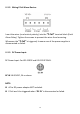
STEP1. Insert the upper end of the DIN-Rail mounting bracket into the
DIN-Rail track from its upper side.
STEP2. Lightly push the bottom of the DIN-Rail mounting bracket into the
track.
STEP3. Check if the DIN-Rail mounting bracket is tightly attached to the
track.
II-2. Powering the Switch
Connect the power source (sold separately) to the switch. Connect the power
adapter to the DC-jack or connect a DIN-Rail power source to the power
terminal block. (Power adapter and DIN-Rail power supply NOT included)
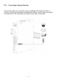
II-2-1. Wiring Power Inputs
IGS-1005/IGS-1105P/IGS-1210P supports power redundancy. If either power
supply fails, the switch will keep operating as usual, and hence guarantees a
constant power source for the system.
The P-Fail relay allows taking precautions against potential power failures.
(DIN Rail power supply NOT included)
1. Insert the Negative / Positive DC wires into the PWR1 (V1-,V1+) terminals
respectively. Tighten the screws to prevent the wires from loosening.
2. Redundant Power: Insert the Negative / Positive DC wires into the PWR2
(V2-,V2+) terminals respectively. Tighten the screws to prevent the wires
from loosening.