
User Manual


10
2-1. Please refer to the definition of the terminal blocks chart below. It
is also printed on the motherboard.
GPIO Terminal Block
(J17, 5pins)
GPIO Terminal Block
(J18, 5pins)
Power Terminal Blocks
(J15, 2pins)
Pin No.
Function
Pin No.
Function
Pin No.
Function
Pin 1
AGND
Pin 1
GND
Pin 1
DC 12V
Pin 2
Audio Out
Pin 2
Alarm In1
Pin 2
GND
Pin 3
Ext MIC In
Pin 3
Alarm In2
Pin 4
RS485 D+
Pin 4
Alarm Out
Pin 5
RS485 D-
Pin 5
GND
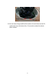
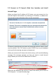
4. Insert all your cables through the conduit hole (optional A or B). If
necessary, use the standard M20x15 water proof straight plug to prevent
the device from water or dirt. Or the other equivalence plug to assembly. (See
Appendix I)