
Multi Format Video Switcher INSTRUCTIONS V-44SW E1

48
Using the V-44SW with Other Devices
V-LINK ( ) is a function that allows music and
images to be performed together. By using MIDI to connect
two or more V-LINK compatible devices, you can easily enjoy
performing a wide range of visual effects that are linked to the
expressive elements of a music performance.
When V-LINK mode is on, you can have control of the V-44SW
be synchronized to the performance of a V-LINK compatible
instrument (such as the Fantom-X).
●
For more on how to switch V-LINK mode on and off, refer to the
Owner’s Manual of the V-LINK compatible device connected to
the V-44SW.
●
To see which functions can be controlled from the external device
while V-LINK mode is in effect, refer to the MIDI Implementation
for the connected device and the V-44SW’s MIDI Implementation.
The functions that can be controlled may vary according to the
connected device and the settings.
The MIDI Implementation for the V-44SW can be downloaded
from the Roland Systems Group website.
http://rolandsystemsgroup.net
●
\o You can have the [MIDI] button light up or go off to show
whether V-LINK mode is on or off. Select “9. MIDI Setup” in the
menu and set “1: MIDI Sw Mode” to “V-LINK Indicator.”
Parameters settings under the initial V-LINK status (whereby
the V-44SW receives only the V-LINK ON message) are
shown below.
You can use the REMOTE connector to enable switching,
control of effects, and other operations from a computer or
other external control device.
The V-44SW’s REMOTE connector is a 9-pin male D-sub
connector. Be sure to use an RS-232C cable to connect the
control device.
An RS-232C cable (D-Sub, 9-pin, female-female) is the proper
cable for connecting a computer.
Cable Connections:
●
Use an RS-232C cable with a connector that matches the
connector on your device.
1
Connect the V-44SW and control device with an
RS-232C cable.
2
Turn on the power to the control device.
3
Set the communications protocol for the control
device.
4
Turn on the power to the V-44SW.
5
Begin operation.
●
For more detailed information about commands, refer to the
“REMOTE Command Reference” (p. 60).
Control Using V-LINK
What is V-LINK?
How to Use V-LINK
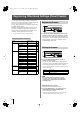
Initial V-LINK Status Settings
Parameter
Initial Status
Rx Channel
1
Tx Channel 1
Channel Select Buttons SD VIDEO [1] button
TRANSITION Select Buttons [MIX] button
[TRANSITION TIME] Knob 0.0 (sec.)
[KEY] Button OFF
[P in P] Button OFF
PANEL PRESET Buttons OFF
Output Fade Mode Auto
OUTPUT FADE Level MAX (No fade)
Controlling the V-44SW from an
External Device Using the
REMOTE Connector
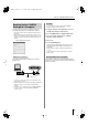
About Connections
Setup Procedure
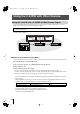
1 : DCD
2 : RXD
3 : TXD
4 : DTR
5 : GND
6 : DSR
7 : RTS
8 : CTS
9 : RI
1 : DCD
2 : RXD
3 : TXD
4 : DTR
5 : GND
6 : DSR
7 : RTS
8 : CTS
9 : RI
V-44SW Computer
15
69
15
69
V-44SW_e.book 48 ページ 2006年10月23日 月曜日 午後3時25分