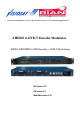
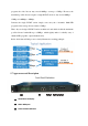
RIAN BV Bergstraat 25 5581 BL Waalre 040-2213656 mailbox@rian-bv.nl 4 HDMI to DVB-T Encoder Modulator (MPEG-2 HD/MPEG-4 HD Encoding + DVB-T Modulating) SW Version: 1.07 HW version: 0.1 Web NMS version: 1.
Directory CHAPTER 1 INTRODUCTION ................................................................................................................... 1 1.1 PRODUCT OVERVIEW ......................................................................................................................... 1 1.2 KEY FEATURES .................................................................................................................................. 1 1.3 SPECIFICATIONS ...............................................
CHAPTER 6 APPLICATION ..................................................................................................................... 32 CHAPTER 7 PACKING LIST .....................................................................................................................
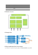
Chapter 1 Introduction 1.1 Product Overview All-in-one devices which integrate encoding (MPEG-2 HD, MPEG-4/AVC H.264) and modulation (DVB-C, DVB-T, ISDB-T, or ATSC) to convert V/A signals into RF output. It has equipped with 4 HDMI channels input and 1 ASI input and output with 2 ASI ports and 1 UDP IP port. It adopts inner drawer-type structural design which greatly facilitates the change of encoding modules (HDMI/CVBS/SDI/YPbPr/…) as needed.
RF Frequency range 30Mhz~960Mhz LCD display, Remote control and firmware Web NMS management; Updates via web Lowest cost per channel --- breakthrough price 1.3 Specifications Encoding Section Video Encoding MPEG2 HD/MPEG4 HD Input HDMI*4 Resolution 1920*1080_60P, 1920*1080_50P, (-for MPEG4/H.
Power supply AC 100V~240V Dimensions 482*400*44mm Weight 4.5 kgs Operation temperature 0~45℃ 1.4 Schematic Overview 1.5 Principle Chart 1.
program, the video bit-rate may exceed 10Mbps, even up to 15Mbps. However, the maximum possible bit-rate output for single DVB-T carrier is only around 30Mbps. 15Mbps x4 =60Mbps > 30Mbps. It means the single DVB-T carrier simply can't carry the 4 channels 1080i HD programs if the average bit-rate reaches 15Mbps.
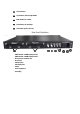
④ Lock Indicators ⑤ Up and down, left and right button ⑥ Enter button: for confirm ⑦ Menu button: for back step ⑧ Lock button: press to lock set Rear Panel Illustration HDMI Module 1: HDMI input port 1&2 HDMI Module 2: HDMI input port 3&4 RF in port (for combiner use) RF out port ASI input port ASI output ports Switch Power supply slot Grounding
Chapter 2 Installation Guide This section is to explain the cautions the users must know in some case that possible injure may bring to users when it’s used or installed. For this reason, please read all details here and make in mind before installing or using the product. 2.1 General Precautions Must be operated and maintained free of dust or dirty. The cover should be securely fastened, do not open the cover of the products when the power is on.
Space the distance between 2 rows of machine frames should be 1.2~1.5m and the distance against wall should be no less than 0.8m.
The area of the conduction between grounding wire and device’s frame should be no less than 25 mm2. Chapter 3 Operation 3.
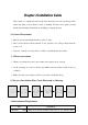
3.2 Initial Status Switch on the device and after a few seconds’ initialization, it presents start-up pictures as below: Start up… Start OK… DVB-T A XXX.00MHz P1:X.XXMbps P2: X.XXMbps DVB-T: indicate the modulation standard of this device A: carrier output A; B: carrier output B XXX.XX MHz indicates the current output frequency (range: 30~960MHz) of its corresponding carrier output. P1: Program 1; P2: Program 2; P3: Program 3; P4: Program 4 X.
3.3 General Settings for Main Menu Press “Lock” key on the front panel to enter the main menu.
MPEG2 Video Format Video Bit Rate H.264 Video Bit Rate 14.000 Mbps MPEG2 Audio Format Audio Bit Rate 64 Kbps 96 Kbps “Video Format”: the HDMI MPEG2 HD encoding module supports both MPEG2 and H.264 formats. Move the triangle mark with LEFT/RIGHT keys to specify the intended format and press ENTER to confirm. “Video Bit Rate”: Move the underline with LEFT/RIGHT keys and modify the value of frequency with UP/DOWN keys, and press ENTER key to save the settings.
“Parse Program” is for checking the quantity of input programs from the corresponding Tuner input. “Select Program A (or B)” is for selecting programs from the ASI IN to output through Carrier A (or B). Move the triangle mark to specify the program and press RIGHT/LEFT keys to shift the mark between “√” and “X”.
Constellation There are three different constellations QPSK, 16QAM and 64QAM shown on the LCD window. When entering Constellation, user can apply the same setting method as mentioned above to select and confirm one mode. Constellation QPSK 16QAM 64QAM Transmission Mode When user enters Transmission Mode, the LCD would show the current working mode. User can move LEFT/RIGHT keys to select and press ENTER key to confirm.
LCD display would show them, users just need press LEFT and RIGHT buttons to choose and press ENTER button to confirm. Code Rate 1/2 2/3 3/4 5/6 RF Frequency The RF output frequency range is from 30 to 960MHz with 1K stepping. After entering the RF frequency setting submenu, users the can press LEFT, RIGHT, UP, and DOWN buttons to adjust the frequency and confirm by press ENTER button. RF Frequency 750.000 MHz RF Out Level The RF attenuation range is -30~-10dbm (81~97dbµV) with 0.1db step.
Output A: the ASI output programs are same as carrier output A. Output B: the ASI output programs are same as carrier output B. ASI Output Output A 4) Output B IP Output Setting The NDS3542A encoder & modulator is with two dual-carrier output (Output A and Output B), 4.1 and 4.2 are for the settings of the two carrier output respectively. Submenus go as 4.1.1-4.1.6. 4.1 IP Output A 4.2 IP Output B 4.1.1 IP Output 4.1.2 Service IP 4.1.3 Output IP 4.1.4 Subnet Mask 4.1.5 Gateway 4.1.
IP Address 192.168.000.136 Subnet Mask 255.255.255.000 Gateway 192.168.000.001 MAC Address ffffffffffffffffffffff Reset Password? Yes NO Web Manage Port 00080 NOTE: The MAC address is according to the factory setting, and it is unique. It can only be modified through special software. 6) Saving Configuration Users can enter Saving Configuration submenu for saving settings. Choose yes and press ENTER to confirm.
this submenu. Encoder Modulator SW 1.07 HW 0.
Chapter 4 WEB NMS Operation User not only can use front buttons to set configuration, but also can control and set the configuration in computer by connecting the device to web NMS Port. User should ensure that the computer’s IP address is different from the NDS3542’s IP address; otherwise, it would cause IP conflict. 4.1 login The default IP address of this device is 192.168.0.136. (We can modify the IP through the front panel.
4.2 Operation When we confirm the login, it displays the WELCOME interface as Figure-2. Device standard and name It automatically identifies and displays the signal source interface and real-time encoding bit rate of corresponding input channel. User can click any item here to enter the corresponding interface to check information or set the parameters. TS indicators—Green light indicates the TS is normal, which otherwise turns to red. Figure-2 “A” & “B” respectively represent carrier A and carrier B.
General Settings for the HDMI IN program: User can edit any item listed as needed. Encoding Status—Green light indicate it works normally, which otherwise turn to red. Figure-3 Carrier A: Click this box to enable or disable the program output through Carrier A. Carrier B: Click this box to enable or disable the program output through Carrier B.
Figure-4 Select the carrier output channel for the multiplexed programs. If this item is selected, all the input programs will pass through without any elimination. Selecting this item to allow user select programs as required to output. Click “Refresh Input” to refresh the input program list. Click “Refresh Output” to refresh the output program list. When user checks one input program with “√”, one can transfer the checked program to the right box to output.
one-time clicking. Time limitation to parse the input programs Click this button to trigger a dialog box as below, where to add the PIDs which need pass through. In some occasions, there are some PIDs which won’t belong to any program, such as EPG, NIT tables and so on which user just wants to pass them through the multiplexing module without changing anything. This is the main purpose of this function. Click “Add” to add more boxes for filling the Input & Output PIDs, then click “Apply” to confirm.
Figure-5 Select the carrier output channel for the inserted NIT. Click “Add” from this page, it will display the screen as Figure-6 where it requires to add Service ID and configure other parameters for the programs. Figure-6 Here by clicking “Add”, users can set the program LCN in its respective field.
setting. As Figure-7, click “Update NIT” to update the NIT information. Figure-7 IP Output Click “IP Output” from the left menu, it will display the screen as Figure-8 where to set the multicast IP Output address for the device if needed and set the IP output for the programs. After setting the parameters, click “Apply” to save the setting. Figure-8 Modulator Setting Enter in “Modulator” and it will display the Modulator Configuration screen as Figure-9 where can set modulation parameters.
RF On – To decide whether to enable the selected RF (carrier A/B) output or not. Bandwidth –Bandwidth selecting. (The default bandwidth is 8M) Constellation –QAM type selecting. (The default constellation is 64QAM) Transmission Mode –2K, 8K optional Guard Interval/Code Rate/RF Frequency/RF Out level – the default configuration is as shown on Figure 9. ASI Output– Carrier output channel selecting (Output A: The ASI output programs are same as carrier output A.
the device. By using “Factory Set” user can import the default factory configuration. Figure-10 Restart the Device Click “Reboot” from the menu, the screen will display as Figure-11. Here when clicking “Reboot” box, it will restart the device automatically. Figure-11 Update the Device Click “Firmware” from the menu it will display the screen as Figure-12. Here user can update the device by using the update file.
Click “Browse” to find the path of the device update file for this device then click “Update” to update the device. After updating the device, user needs to restart the device by using Reboot option. Browse Button Figure-12 Network When user clicks “Network”, it will display the screen as Figure-13. It displays the network information of the device. Here user can change the device network configuration as needed.
Change Password When user clicks “Password”, it will display the password screen as Figure-14. Here user can change the Username and Password for login to the device. After putting the current and new Username and Password, click Apply” to save the configuration. Figure-14 Keyboard and LCD Lock: If it is marked with “√”,the LCD and keyboard will be locked to avoid unrelated users’ modifying or view the device information and configurations.
“Load File” to load the backup file to the device.
Chapter 5 Troubleshooting DIGITAL INNOVATIONS’s ISO9001 quality assurance system has been approved by CQC organization. For guarantee the products’ quality, reliability and stability. All DIGITAL INNOVATIONS products have been passed the testing and inspection before ship out factory. The testing and inspection scheme already covers all the Optical, Electronic and Mechanical criteria which have been published by DIGITAL INNOVATIONS.
Maintenance needed Chapter 6 Application Application Examples 1).
5) Cinema Audio Video contents DVB T/ISDB-T distribution 6) Company Audio Video contents distribution
Chapter 7 Packing List NDS3542A Encoder Modulator 1PC User's Manual 1PC HDMI Cables 4PCs Power Cord 1PC
APPENDIX Our encoder & modulator series are individual-module design, and the encoding modules include: MPEG2 SD super encoding with 2 CVBS in MPEG2 encoding with 1CVBS in MPEG4 AVC H.264 encoding with 1 or dual SDI in DVB-S2 tuner input YPbPr +HDMI +CVBS input MPEG4 AVC/H.