
User guide


Installation Instructions for Edwards AdaptaLight
TM
Heavy Duty Industrial Stackable Beacons
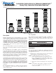
Figure 1. Dimensions
Description
Edwards AdaptaLight Series 101 Stackable Beacon is a unique
signaling appliance which can contain up to five modules, stacked
onto a single AdaptaLight Base Unit (as illustrated above).
AdaptaLight Modules are available in Steady-On Incandescent
(101SIN), Steady-On Halogen (101SINH), Steady-On LED
(101SLED), Flashing Incandescent (101FIN), Flashing Halogen
(101FINH), Flashing LED (101FLED), or Strobe (101ST). Up
to five modules can be used in any position in the AdaptaLight
Stackable Beacon.
The 9 watt halogen bulb is rated by the manufacturer at 52 lu-
mens. The 12 watt halogen bulb is rated by the manufacturer at
70 lumens.
The AdaptaLight base unit (101BS) contains a mini pulsating
horn rated 85 dB at 10 feet (3.05 m). This horn can operate as a
sixth independent signal or with any one of the stacked modules.
The base unit has a screw-type terminal strip for positive hard
wiring. Each module in the stack is electrically interconnected
through solid copper busses and mating contacts to withstand vi-
bration. Each is positively connected to the one below it by a
solid through-bolt for mechanical integrity.
AdaptaLight is UL and cUL listed for direct surface or pipe mount-
ing in non-hazardous dust and weatherproof applications. The
AdaptaLight may be mounted vertically with lenses facing up or
with lenses facing down (on ceiling). The AdaptaLight is not
suitable for weatherproof installations when mounted with the
lenses facing down. The AdaptaLight must never be mounted
horizontally. Assemble and install in accordance with these in-
structions.
The AdaptaLight modules have double fresnel polycarbonate
lenses available in a variety of colors, each providing a 360° non-
shadowed light pattern.
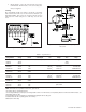
PLC Compatibility
The electrical input load requirements for PLC compatible sig-
naling devices are listed in Table 1. Signaling devices may be
directly connected to output cards that meet these input load re-
quirements.
To prevent electrical shock, do not connect power
until instructed to do so.
WARNING
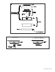
Installation
This equipment must be installed by a qualified electrician in
accordance with the latest edition of the National Electrical Code
and applicable local codes.
1. Mount the base vertically either facing up or down using one
of the following procedures (Figures 2 and 3).
NOTE: For indoor applications, the base may be direct
surface mounted, mounted on a 4" (102 mm) octagon
box, or mounted on 1/2" (13 mm) NPT conduit. For
outdoor (weatherproof) applications, the base must be
conduit mounted vertically facing up.
a. Loosen the screw in the clamp ring, remove ring and set
aside.
NOTE: A permanently affixed gasket is supplied on the base.
Use care when handling the base unit to prevent
tearing of the gasket.
P-047550-1297 ISSUE 6 © 2003
Cheshire, CT 06410 203-699-3300 (Ph)
203-699-3365 (Cust. Serv. Fax)
203-699-3078 (Tech. Serv. Fax)