
User guide


P-047550-1297 ISSUE 6
b. Direct Surface Mounting (indoor installation only)
Remove the two knockouts from the bottom of the base.
Fasten the base to the surface using suitable hardware
(not supplied).
c. 4" (102 mm) Octagon Box Mounting (indoor installation
only)
Remove the two knockouts from the bottom of the base.
Fasten the base to the octagon box (not supplied) by
installing the screws (supplied with the box) through the
knockout holes in the base.
d. Conduit Mounting (indoor or outdoor installation)
Install a 1/2" (13 mm) NPT conduit (not supplied). Align
the conduit entrance hole on the base with the conduit
and rotate base until base is tightly secured.
2. Route incoming field wiring into the base through the conduit
entrance hole.
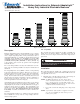
Up to five high-intensity strobe modules, and/or flashing
halogen or LED modules, and/or steady-on halogen or LED
modules can be used in any position in the stack. The terminal
block labels, 1 through 5, correspond to the stacked modules
with 1 being the bottom module on the stack.
Connect field wiring to the terminal block as shown in Figure
4.
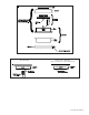
Ground the AC AdaptaLights to the grounding screw (Figure
3) in accordance with applicable codes. Place the connected
wires inside of the base.
Assemble the base unit and place the base gasket on top as
shown in Figure 2.
3. To stack the modules, align the notch on the bottom of the
first module with the notch on the base and press into position.
Secure by tightening the slotted panhead through-bolt located
on the top of the module.
NOTE: Never try to remove the through-bolt from the module.
Install the #8-32 x 3/8" (9.5 mm) plastic panhead screw in
the side of the module lens (Figure 5).
Place gasket supplied with module onto the top of the module.
Continue adding modules in this manner as required.
Place the cap supplied with the base unit onto the top module
ensuring the gasket is in place. Secure with an o-ring and 3/
8" (9.5 mm) cap screw (supplied).
4. Turn on power and verify that module(s) and horn are
operating properly.
Maintenance
Refer to "Specifications" for replacement parts.
WARNING
To prevent electrical shock, disconnect all power
and wait 5 minutes for stored energy in strobe
modules to dissipate before starting work on unit.
1. Remove the 3/8" (9.5 mm) cap screw, o-ring and cap from
top of unit.
2. Remove the #8-32 x 3/8" (9.5 mm) plastic panhead screw
from the side of the module lens.
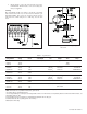
Table 1. PLC Compatibility
Operating Maximum off state Continuous on Surge (inrush/duration)
Cat. No. voltage* leakage current (mA) current (mA) (A/ms**)
101BS-G1 24V DC 25 50 2/1
101BS-N5 120V AC 25 50 2/1
101SINH( )-G1 24V DC 25 320 0.36/1
101SINH( )-N5 120V AC 25 110 0.5/8
101SLED( )-G1 24V DC 4 65 0.07/1
101SLED( )-N5 120V AC 5 25 0.09/8
101FINH( )-G1 24V DC 25 320 1.2/100
101FINH( )-N5 120V AC 25 110 1.15/8
101FLED( )-G1 24V DC 4 65 0.07/1
101FLED( )-N5 120V AC 5 25 0.09/8
101ST( )-G1 24V DC 1.5 300 0.33/1
101ST( )-N5 120V AC 5 120 2.1/1
*All AC volts at 60 Hz
**Amps/milliseconds