
User guide


P-047550-1297 ISSUE 6
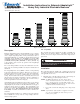
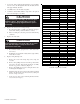
Steady-On Incandescent Light Unit*
120V AC 12V DC 24V DC Lens Color
101SINHR-N5 101SINR-E1 101SINHR-G1 Red
101SINHA-N5 101SINA-E1 101SINHA-G1 Amber
101SINHB-N5 101SINB-E1 101SINHB-G1 Blue
101SINHG-N5 101SING-E1 101SINHG-G1 Green
101SINHM-N5 101SINM-E1 101SINHM-G1 Magenta
101SINHC-N5 101SINC-E1 101SINHC-G1 Clear
Steady-On LED Light Unit
120V AC 24V DC Lens Color
101SLEDR-N5 101SLEDR-G1 Red
101SLEDA-N5 101SLEDA-G1 Amber
101SLEDB-N5 101SLEDB-G1 Blue
101SLEDG-N5 101SLEDG-G1 Green
Flashing Incandescent Light Unit*
120V AC 12V DC 24V DC Lens Color
101FINHR-N5 101FINR-E1 101FINHR-G1 Red
101FINHA-N5 101FINA-E1 101FINHA-G1 Amber
101FINHB-N5 101FINB-E1 101FINHB-G1 Blue
101FINHG-N5 101FING-E1 101FINHG-G1 Green
101FINHM-N5 101FINM-E1 101FINHM-G1 Magenta
101FINHC-N5 101FINC-E1 101FINHC-G1 Clear
Flashing LED Light Unit
120V AC 24V DC Lens Color
101FLEDR-N5 101FLEDR-G1 Red
101FLEDA-N5 101FLEDA-G1 Amber
101FLEDB-N5 101FLEDB-G1 Blue
101FLEDG-N5 101FLEDG-G1 Green
Flashing Strobe Light Unit
120V AC 12V DC 24V DC Lens Color
101STR-N5 101STR-E1 101STR-G1 Red
101STA-N5 101STA-E1 101STA-G1 Amber
101STB-N5 101STB-E1 101STB-G1 Blue
101STG-N5 101STG-E1 101STG-G1 Green
101STM-N5 101STM-E1 101STM-G1 Magenta
101STC-N5 101STC-E1 101STC-G1 Clear
*H in catalo
g
number
(
e.
g
., 101SINHR-N5
)
si
g
nifies halo
g
en module.
3. Loosen the slotted panhead through-bolt (on top module).
Do not remove the through-bolt from the module; turn the
bolt approximately 30 turns.
4. Carefully remove the module and gasket.
5. Continue to disassemble until the component to be replaced
is located and replace as follows.
Stackable Light Units Available
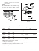
6. Replace the incandescent or halogen lamp.
a. Reach inside module, carefully grasp the lamp and press
down while turning counterclockwise to release.
b. Place new lamp in socket and press down while turning
clockwise.
7. Replace the strobe tube.
CAUTION
To prevent damage to the lamp,
do not
touch glass
with bare fingers. Grasp glass with a soft, clean
cloth or with packaging supplied with the replace-
ment lamp.
a. Reach inside module, grasp the base of the strobe tube
and remove.
b. Holding the new strobe tube only by its base (if possible),
insert tube in socket.
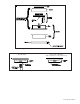
8. Replace mini pulsating horn.
a. Remove the screw in the clamp ring, remove ring and
set aside.
b. Remove three phillips head screws from top of base skirt
and remove the base skirt and the base/horn assembly
from the top portion of the base (Figure 2).
c. Remove the phillips head screw securing the horn to the
mounting bracket (Figure 2).
d. On DC models, disconnect wire leads from the terminal
blocks. On AC models, disconnect wires by cutting off
the wire crimp connectors.
e. Secure the new horn on the mounting bracket with the
screw removed in step 8.c.
CAUTION
To prevent damage to the strobe tube,
do not
touch
glass with bare fingers. Grasp the base of the
replacement strobe tube.