
Owner manual

301
301-CT-06K
301-CT-12K
301-DT-06K
301-CT-12K-CD
Interlock Switch
Installation
Use non-removable screws, bolts, or nuts to mount the switch and actuator. Do not
over-torque mounting hardware.
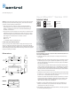
1. Position the switch and actuator so the labels are reading in the same direction
(See Figure 1).
2. Mount the switch on the stationary frame of the machine and mount the actuator on
the moveable guard, door or gate. To determine the optimum sense range, shown
under the Ordering/Electrical Specifications for each product, attach an ohmmeter
to the black and white wires.
The meter should read “Infinity” with the actuator away from the switch. Bring the
actuator toward the switch until the meter reads 0 ohms. Mark this point and bring
the actuator closer to the switch until the meter again reads “Infinity.” Mark this
point and position the actuator between the two marks. Align the actuator with the
switch so the labels read in the same direction.
* (For DT models, which incorporate a triac, the meter will read some resistance when
the switch is “on,” and the direct current (DC) from the meter may cause the switch
to latch in the “on” state until the meter is disconnected).
The switch and actuator must be mounted so that the actuator moves in one of the
approved directions (Figure 2 Mounting Configurations). Parallel actuation is NOT
recommended. An on/off/on signal may result when the actuator passes by the
switch rather than coming to rest in proximity to it.
3. Mounting on a ferrous material will effect the sense range a minimum of 50%.
However, a 1/4" nonferrous spacer positioned under the actuator and/or switch
should restore most of the lost sensor range.
4. When mounting a metal switch to an ungrounded machine, connect the ground lead
to one of the switch mounting screws.
Warning! To avoid switch failure determine the actual load of the switch circuit and
take steps to protect the switch from voltage spikes, current inrush and line/load
capacitance using the following recommendations.
• Surges from coils, motors, contactors, solenoids and tungsten filaments.
Transient protection, such as back-to-back zener diodes (Transorb) or an RC
network, is recommended for such loads to ensure that maximum ratings of
the switch are not exceeded.
• Line capacitance and load capacitance. An in-line resistor can beadded in series
immediately before the load to limit the inrush current. The resistor can only be
added in series with the last wire just before the load. The voltage drop and the
power rating of the resistor must also be calculated as follows:
Voltage drop = I • R
Watts = I
2
• R
( I = maximum continuous current of the load)
To verify switch operation with an ohmmeter:
Set range at 20 mega ohms (switches with triac output, set ohm range at 20 kilo
ohms). For a normally open switch, the meter will read a high impedance with the
actuator away. It will read very high to infinity range (triac switches will read high kilo
ohm to infinity range) with the actuator within sense range. You will see the opposite
reading for a normally closed switch.
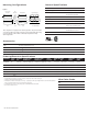
Dimensions
Figure 1
303
0.67''
1.70cm
3.07''
7.80cm
1.75''
4.45cm
0.74''
1.88cm
0.98''
2.49cm
0.57''
1.45cm
3.07''
7.80cm
0.66''
1.68cm
0.20''
0.51cm
0.16'' x 0.24''
0.41cm x 0.61cm
slot
1.48''
3.76cm
0.40''
1.02cm
2.13''
5.41cm
0.69''
1.75cm
Actuator
Switch
sensing face
sensing face
301-CT-30k
301-DT-12K
301-________
303-________
GuardSwitch
™
Series 300
www.edwardssignaling.com