
Owner manual

Ordering/Electrical Specifications
General Specifications
Enclosure 304 Folded Stainless steel
Temperature Range -40°F to 180°F (-40°C to 80°C)
Environmental Hermetically Sealed Contact Switch
Encapsulated in Polyurethane
NEMA Rating 1, 2, 4, 4X, 5, 12
Protection Class IP 66
Response Time 1 msec (5.4VA); 10 msec (150VA)
Life Cycles 100,000 Under Full Load;
Up to 200,000,000 Under Dry Circuit
Lead Types/O.D. SJTOW (K)18/2 AWG/0.30" (0.76cm)
18/4 SJTOW (K)/0.34" (0.86cm)
UL/CSA All Models
PART NUMBER
1
CONTACT
2
LOAD RATING SWITCHING VOLTAGE SWITCHING CURRENT CONTACT NOMINAL SENSE RANGE
3
BREAK RANGE LEAD LENGTH
CONFIG. AC/DC MAXIMUM, AC/DC MAXIMUM, AC/DC RESISTANCE MAX. MIN. NOMINAL NOMINAL
301-CT-06K N.O. 2.5VA/2.5W 30V@0.08A 30V@0.08A 0.18A@13.8V 0.18A@13.8V 0.5 Ohms 0.75"(1.9cm) 0.375"(1.0cm) 1.2"(3.0cm) 6'(1.8m)
301-CT-12K N.O. 2.5VA/2.5W 30V@0.08A 30V@0.08A 0.18A@13.8V 0.18A@13.8V 0.5 Ohms 0.75"(1.9cm) 0.375"(1.0cm) 1.2"(3.0cm) 12'(3.6m)
301-CT-12K-CD DPST/2 N.O. 2.5VA/2.5W 30V@0.08A 30V@0.08A 0.18A@13.8V 0.18A@13.8V 0.5 Ohms 0.75"(1.9cm) 0.375"(1.0cm) 1.2"(3.0cm) 12'(3.6m)
301-CT-30K N.O. 2.5VA/2.5W 30V@0.08A 30V@0.08A 0.18A@13.8V 0.18A@13.8V 0.5 Ohms 0.75"(1.9cm) 0.375"(1.0cm) 1.2"(3.0cm) 30'(9.1m)
301-DT-06K
5
N.O./ 150VA/NA 120V@1.25A NA 1.25A
4
@120V NA NA 0.75"(1.9cm) 0.375"(1.0cm) 1.2"(3.0cm) 6'(1.8m)
301-DT-12K
5
N.O./ 150VA/NA 120V@1.25A NA 1.25A
4
@120V NA NA 0.75"(1.9cm) 0.375"(1.0cm) 1.2"(3.0cm) 12'(3.6m)
Warning— Each electrical rating is an individual maximum and cannot be exceeded!
1
The part numbers 301 and 303 are the same in all respects except the cable exits 301 left and 303 right.
2
Configuration with actuator away from the switch
3
Proximity of ferrous materials usually reduces sense range — typically by 50%. The shape and type of material cause a wide diversity of effects.
Testing is required to determine actual sense range for specific applications.
4
Can withstand inrush surge up to 4 amps. Voltage drop is 1.5V. Minimum Switch Current 30mA.
5
Do not exceed 10 switches in series.
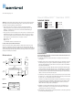
Mounting Configurations
Perpendicular
Actuation
Door
Actuation Parallel Actuation
Best
Best Not Recommended
Pivot Actuation
Good
Three configurations are appropriate for interlock applications. The parallel actuation
can result in on/off/on signal if the actuator passes by the switch rather than coming
to rest in proximity to it. This is NOT a recommended configuration for safety
interlock applications.
Figure 2
File E 122942
LR89176
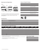
Accessories
PART NUMBER TAMPER PROOF SCREWS & SCREWDRIVER
1953 #6 x 3/4"L Tampruf
Roundhead Screw
1954 #8 x 1-1/2"L Tampruf Roundhead Screw
1955 Tampruf
®
Screwdriver
1956 Tampruf
®
1/4" Drive Bit for #6 and #8 Screws
triac
output
triac
output
Wire Color Codes
DPST
Circuit 1 Black and White
Circuit 2 Red and Blue
P/N 11508 • REV D • REB 07JUN13