INSTALLATION, OPERATION, AND MAINTENANCE MANUAL FOR ELECTRIC TANKLESS WATER HEATERS SPECADVANTAGE | SAFE ADVANTAGE
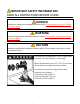
IMPORTANT SAFETY INFORMATION READ ALL INSTRUCTIONS BEFORE USING DANGER Indicates an imminently hazardous situation which, if not avoided, will result in death or serious injury. WARNING Indicates a potentially hazardous situation which, if not avoided, could result in death or serious injury. CAUTION Indicates a potentially hazardous situation which, if not avoided, may result in minor or moderate injury. Hot water can be dangerous. There is a high scald potential if the thermostat is set too high.
IMPORTANT SAFETY INFORMATION READ ALL INSTRUCTIONS BEFORE USING 1. You must read and follow all instructions. Serious bodily injury or death could occur if you ignore this warning. 2. 3. 4. 5. 6. 7. Per UL 499, this water heater is not required to be installed with a Temperature and Pressure relief valve (T&P). However, local codes may vary.
IMPORTANT SAFETY INFORMATION READ ALL INSTRUCTIONS BEFORE USING 10.When the heater is installed in a well 14.This heater must be in a location water system or if the plumbing where it is not subject to freezing system is prone to introducing air into temperatures unless supplied with the heater, it is highly recommended factory installed freeze protection that an air separator be installed in the cold water feed to the heater to avoid 15.
iv
TABLE OF CONTENTS PERFORMANCE FEATURES................................................................................................................. 1 OPERATION PRINCIPLE ...................................................................................................................... 3 MOUNTING THE HEATER TO THE WALL ............................................................................................. 4 ELECTRICAL HOOKUP .......................................................................
PERFORMANCE FEATURES Heating Technology Field Replaceable, non-ferrous, lead-free cartridge-style direct heating element Safety and Reliability Thermo-Optical sensor for protection against entrained air or improper commissioning Materials and Construction NSF-61 listed materials of construction Control and Consumption Active energy management to ensure optimal application of energy based on real-time system demands Multistage element turn-on Visual user interface for field programming Tu
2
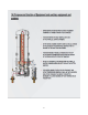
OPERATION PRINCIPLE How the Eemax Tankless Water Heater Works Operating the new Eemax tankless water heater is similar to using any traditional water heater system. However, it is very important that all of the set-up procedures and operating instructions are carefully read to ensure maximum performance and energy savings from the water heater. The Eemax tankless water heater does not store hot water like a conventional tank-type water heater.
MOUNTING THE HEATER TO THE WALL Please follow the mounting instructions as appropriate to your installation. Eemax recommends the heater be installed close to the point of use. CAUTION This heater must be installed in a location where it is not subject to freezing temperatures, unless supplied with factory installed freeze protection Make sure the brass fittings are at the bottom of the heater. No other heater orientation is permitted.
ELECTRICAL HOOKUP Eemax recommends your heater be installed or serviced by a licensed plumber and electrician. WARNING Before beginning any work on this installation, BE SURE THAT THE ELECTRICAL BREAKER IS “OFF” AND THAT ALL MOUNTING AND PLUMBING WORK HAS BEEN COMPLETED PER THESE INSTRUCTIONS. This heater must have its own independent circuit using insulated, UL listed wire conductors of the appropriate size suitable for up to 90° C and protected by the correctly rated circuit breaker.
Electrical Specifications VOLTS 3-PHASE DELTA KW AMPS PER PHASE RECOMMENDED WIRE SIZE (CU) 90° C AP032208 208 32 89 1 AWG AP036208 208 36 100 1 AWG AP041208 208 41 114 1 AWG AP054208 208 54 150 2/0 AP064208 208 64 178 3/0 AP036480 480 36 44 8 AWG AP039480 480 39 47 8 AWG AP048480 480 48 58 6 AWG AP054480 480 54 65 4 AWG AP063480 480 63 76 3 AWG AP072480 480 72 86 3 AWG AP096480 480 96 116 1 AWG AP108480 480 108 130 1/0 AP126480 480 126
PLUMBING HOOKUP MUST FLUSH LINE A MINIMUM 5 MINUTES, AT A MINIMUM 15 GPM ON INITIAL START UP The heater is equipped with NPT brass fittings. Make sure ONLY NPT fittings are used for connection to this heater. Connect the cold water line with the inlet connection (RIGHT fitting) Connect the outlet pipe with the outlet fitting (LEFT fitting) Do not reverse connections. HOT WATER OUT COLD WATER IN CAUTION Never use pipe dope when making plumbing connections to this heater.
WARNING MUST FLUSH OUT WATER HEATER FOR MINIMUM 5 MINUTES AT A MINIMUM 15 GPM ON INITIAL START UP OR AFTER ANY SERVICE WORK HAS BEEN PERFORMED. CLOSE AND OPEN DRAIN VALVE 3 TIMES TO REMOVE ANY LODGED AIR BUBBLES. FAILURE TO DO SO MAY DAMAGE THE HEATER. MINIMUM INLET WATER PRESSURE 35 PSI DYNAMIC. MAXIMUM WATER PRESSURE NOT TO EXCEED 150 PSI. RECOMMENDED OPERATING PRESSURE 60 – 90 PSI. USE OF A PRESSURE REGULATOR RECOMMENDED.
Proper water conditions must be maintained to prevent damage to the water heater. CONSTITUENT (MG/L) MINIMUM REQUIREMENT BETTER BEST Alkalinity 50 25 10 Calcium 25 5 0.5 Carbon Dioxide 0 0 0 100 15 1 1 1 0.05 Iron 0.2 0.1 0.01 Magnesium as Mg 0.5 0.1 0.1 Magnesium as Mn 0.1 0.1 0.1 Nitrate 25 25 10 Oxygen 2 1 0.1 Silica 15 10 1 Sodium 50 10 1 Sulfate 25 25 1 TDS* 200 100 5** Total Hardness 25 10 1 6.5 – 8.5 6.5 – 8.5 6.5 – 8.
COMMISSIONING THE WATER HEATER CAUTION BEFORE SWITCHING THE ELECTRICAL BREAKER “ON”, MAKE SURE THE INLET AND OUTLET BALL VALVES ARE FULLY OPEN AND WATER IS FLOWING THROUGH ALL POINTS OF USE FOR A MINIMUM OF 5 MINUTES AT A MINIMUM 15 GPM. Open and close drain valve 3 times while purging to remove any lodged air bubbles. DO NOT SWITCH THE BREAKER “ON” IF THERE IS ANY POSSIBILITY THE WATER IN THE HEATER IS FROZEN.
Startup Process Plumbing Installation Checklist MUST BE FILLED OUT AND LEFT WITH WATER HEATER. MUST FLUSH WATER HEATER FOR MINIMUM 5 MINUTES AT A MINIMUM. Eemax Installation Checklist and Startup Procedure for SafeAdvantage and SpecAdvantage Water Heaters Important - Read and fully understand all steps outlined below before proceeding. Failure to do so may damage the water heater and void any warranty.
Important - Read and fully understand all steps outlined below before proceeding. Failure to do so may damage the water heater and void any warranty.
Shutdown Process (Normal, Emergency, and Long Term) Shut Down Procedure Important - Read and fully understand all steps outlined below before proceeding. Failure to do so may damage the water heater and void any warranty.
MONITORING & PREVENTIVE MAINTENANCE Recommended routine instrument readings and operation checking: Please note the instrument readings are performed during water heater operation. No readings are required when the unit is not being used.
CONTROL FEATURES CAUTION BEFORE USING THIS CONTROL, make sure all prior installation steps have been properly completed, electrical power is on and water is present in the heater. Push Button Flow Chart 1) The SETPOINT TEMP or ACTUAL TEMP screen can be selected for display as the home screen. Either of these screens will remain on the display when the backlight timer expires. SETPOINT TEMP120F 2) There is a 5-minute time delay built into the control.
8) From the LOAD PCT screen, one press of the RIGHT button will shift the display to the FLOWRATE screen. This shows the rate of flow of water through the heater. LOAD PCT 0% PWR FLOWRATE ??? GPM 9) From the FLOWRATE screen, one press of the RIGHT button will shift the display to the UNITS screen. This shows the units of measure in either the ENGLISH or METRIC systems. ENGLISH units are degrees Fahrenheit and gallons per minute. METRIC units are degrees Celsius and liters per second.
12) FAULTS are communicated through the LCD display. The display will switch from the SETPOINT screen to the FAULT screen and back again every 3 seconds. FAULTS indicate an undesirable condition and will immediately shut down the operation of the heater. If faults are appearing on your heater call Eemax Technical Support for assistance.
TROUBLESHOOTING PROCEDURES If you need any assistance from our Technical Service Department, make sure you can identify this water heater by having the model number and serial number. Model No. ______________________________ Serial No. ______________________________ Call 203-267-7890 TOLL FREE: 1-800-543-6163 Eemax.Support@eemax.com PROBLEM Unit does not power on POSSIBLE CAUSES Display FAULT F0 IF FALSE Proceed to Action A1 Check main power supply voltage is within +/- 5% of nominal.
Flow rate is too high A14 Element failure Power off, Using a multimeter check A15 continuity at between red and black wires at each element chamber Check LOAD PCT for 100% load Reduce flow rate, heater is operating outside of capability A15 A16 No continuity- replace heater element. Check water quality Verify SSR/Triac functionality by checking current draw off each Heating Elements A16 SSR/Triac by means of an amp not modulating clamp.
TECHNICAL SUPPORT TECHNICAL SUPPORT FORM PERFORM STEPS BELOW BEFORE CALLING TECHNICAL SUPPORT 1 (800) 543-6163 WATER HEATER MODEL # ____________________________________ SERIAL # ____________________________________ Inlet Water Pressure ____________________ Inlet Water Temperature ____________________ Incoming Voltage Testing Elements L1 ____________ Amp draw on each heating element, place clamp on each red wire on inlet side of contactor.
Testing Points Testing optical sensors: Ohm out optical sensors: find jack plug p5 on circuit board and place #1 lead on the blue wire, then place #2 lead on the on the blue wire on the back right optical board. Move #2 lead to each blue wire on optical boards to verify continuity. Repeat with black wire. Lead placement: TEST BLUE AND BLACK SEPERATELY. PUT 1 LEAD ON BLUE WIRE ON P5 PLUG THEN OTHER LEAD GOES TO EACH BLUE WIRE ALONG OPTICAL SENSORS. REPEAT WITH BLACK WIRE.
Configuration Parameters Loading Guide Record and document any error codes on display, inserting USB will erase all code history. Then Disconnect power from the heater by turning off the circuit breaker. ERROR CODES: Your heater may or may not be installed in a NEMA 4/4X cabinet. For units with the NEMA cabinet, remove the 5 mounting screws to remove the cover.
Home screen will appear first. ACTUAL TEMP 73F The heater has recognized the USB drive USB CONN 90 73F CNF file has been successfully loaded-IF “CNF ERR” is displayed, try removing reseating the USB into the slot.
APPLICATIONS SCHEMATICS TYPICAL SAFETY SHOWER or POINT OF USE INSTALLATION 24
SINGLE IN RECIRCULATION LOOP Eemax.Support@eemax.
RECIRCULATION LOOP THROUGH HEATER OPTION 1 Eemax.Support@eemax.
SINGLE WATER HEATER Eemax.Support@eemax.
SINGLE HEATER WITH TANK Eemax.Support@eemax.
SINGLE HEATER WITH TANK WITH RECIRCULATION LOOP Eemax.Support@eemax.
SERIES APPLICATION Eemax.Support@eemax.
SERIES WITH TANK AND RECIRCULATION LOOP Eemax.Support@eemax.
SERIES APPLICATION WITH RECIRCULATION LOOP Eemax.Support@eemax.
PARALLEL APPLICATION Eemax.Support@eemax.
PARALLEL WITH RECIRCULATION LOOP Eemax.Support@eemax.
PARALLEL WITH TANK HEATER Eemax.Support@eemax.
PARALLEL HEATERS WITH CIRCULATORS WITH STORAGE TANKS Eemax.Support@eemax.
PARALLEL HEATER WITH CIRCULATORS WITH DIP TUBE STORAGE TANK Eemax.Support@eemax.
PARALLEL APPLICATION IN LOOP CONFIGURATION Eemax.Support@eemax.
PRIMARY/SECONDARY PIPING INSTALLATION Eemax.Support@eemax.
MULTIPLE HEATERS IN PRIMARY/SECONDARY PIPING INSTALLATION INSTALLATION Eemax.Support@eemax.
RECIRCULATION LOOP WITH LOW LOSS HEADER TEES Eemax.Support@eemax.
STORAGE TANKS WITH HIGH FLOW DEMAND CIRCULATORS/LOW FLOW DEMAND HEATER INSTALLATION Eemax.Support@eemax.
HOT WATER WITH SPACE HEATING Eemax.Support@eemax.
HOT WATER / SPACE HEATING Eemax.Support@eemax.
REPAIRS AND OPTIONS Repair Parts WARNING Service and repairs are to be performed by licensed electricians or qualified servicemen. WARNING Before attempting any repairs to the heater, make sure that the electrical breaker is “off” and confirm that there is no voltage at the heater.
Repair Parts (continued) Triacs Assembly replaced by SSR Model Number Model Number Suffix AP032208 SSR Assemble (incl. 3) ECO Assembly Optical Board Assembly Transformer Fuses EX77000-8.12 B02 EX78000-00 EX08300-00 EX08303-07 EX198 EX78009-00 EX278A-Kit EX78001-00 EE EX77000-8.12 A04 EX78000-00 EX08300-00 EX08303-07 EX198 EX78009-00 EX278E-Kit EX78001-00 AP032208 S EX77000-8.
AP054480 EFD EX77000-12.8 A04 EX78000-01 EX08300-00 EX08303-08 EX08100-07 EX78009-00 EX278E-Kit EX78001-00 AP054480 S EX77000-12.8 B00 EX78000-00 EX08300-00 EX08303-08 EX08100-07 EX78009-00 EX278D-Kit EX78001-00 EX77000-18.2 B04 EX78000-01 EX08300-00 EX08303-08 EX198 EX78009-00 EX278A-Kit EX78001-00 EX77000-18.
Options Optional Class 1 Division 2 Establishing Connections Sizes, Lengths & Bends Typical Single Protected Enclosure Connections Helpful Hints To ensure adequate protective gas flow to the protected enclosure(s), all piping and tubing must be fully reamed. Precautions must be taken to prevent crimping and other damage to protective gas piping and tubing.
NEMA Cabinet 4, 4X, 4X (316) 49
Electrical Supply Requirements General Wiring Requirements WARNING THIS DEVICE CONTAINS ELECTRICAL PARTS WHICH CAN CAUSE SHOCK OR INJURY. All electrical connections, conduit and fittings on the protected enclosure must be suitable for the hazardous location in which they are installed. In addition, all conduit and wire must be installed in accordance with NEC as required and all relevant plant and local codes.
Conduit Installation Electrical Conduit 1. 2. 3. 4. 5. 6. Choose the location for the enclosure's electrical conduit connection(s) based on the requirements on page 49, "Electrical Supply Requirements". Drill and deburr enclosure conduit fitting holes in the protected enclosure. Mount the fittings. Determine appropriate route for the enclosure electrical and power alarm signal conduit Measure, cut and thread conduit, check conduit fit to ensure proper seating. Fully ream all conduit.
Set-up Procedure Helpful Hints “Safe" pressure, for purposes of this manual, is defined To test the vent's operation, gently prod the vent flapper as a minimum .25 inch (6.4 mm) of water column. open with a soft pointed object, (example: eraser end of a pencil) ensuring that the vent valve works freely. On Regulator may be in the locked position upon arrival. To vertically configured vents, this can be accomplished adjust regulator, pull handle to outward position. from within the protected enclosure.
Operating Sequence WARNING Do not exceed “Safe” pressure with the Enclosure Pressure Control Valve. Operators must follow step-by-step sequence of the Start-Up Instructions Nameplate on the Protection System. Class I Purging Operation With the protective gas supply connected, enclosure power deenergized and alarm system energized (if utilized). 1. 2. 3. 4. 5. 6. Carefully read Start-Up Instructions on system. Check operation of the Enclosure Protection Vent (EPV-3) opening it manually several times.
STD WITH EP OPTION (INERT GAS SUPPLIED BY CUSTOMER) 54
AVAILABLE WITH EP-6000 UNIT 55
System Maintenance Regular Maintenance Drain the Protection System Filter (if utilized) frequently and clean system with non-solvent cleaning agents only. Long Term Maintenance Calibrate the enclosure pressure indicator to 0 inches by venting the purge pressure reference port and the protected enclosure to atmosphere and adjusting the calibration screw in the lower center portion of the indicator’s face.
Optional Enclosure Heater 1) Attach heat tape and foam insulation to all lengths of inlet and outlet water piping that are exposed to freezing temperature. We recommend a rating of -30 degrees F at 10 miles per hour wind. Connect the heat tape to an independent source of electrical power. CAUTION Failure to attached heat tape and insulation to exposed inlet and outlet pipes will void the warranty.
Optional GFCI The optional GFCI consist of (A) Control Module and (B) Current Transformer. This control module has a LCD display indicating real-time measurements. The GFCI module is preset from factory to trip at 3.0 A. Test and reset functions are carried out automatically every 24 hours. To manual test the GFCI, press the test button for a minimum of 1.5 seconds. To reset a tripped GFCI, cycle the power of the unit.
Optional NON-FUSIBLE Disconnect Switch DISCONNECT SWITCH MODEL 60 A 100 A 200 A 600 V 600 V 600 V 120 VAC 1-Phase 3 - - 220/240 VAC 1-Phase 10 10 10 220/240 VAC 3-Phase 20 30 75 440/480 VAC 3-Phase 40 75 150 600 VAC 3=Phase 50 100 200 Short circuit rating with fuses 100 200 200 J J J 60 100 200 Operating Voltage Max Horsepower Rating: Branch circuit fuse type Max fuse rating (A) Disconnect Handle NEMA Type: 4, 4X Color: Red/Yellow 59
Optional FUSIBLE Disconnect Switch DISCONNECT SWITCH MODEL 200 AMP 100 AMP 200 A 100 A 600 V 600 V 208 v 50/150 25/78.5 240 v 60/154 30/80 480 v 125/156 60/77 600 v 130/144 75/77 DC 125 V (2 pole in series) 15/112 7.
WIRING SCHEMATICS 120V COM 480V L1 120V 480V L2 RELAY COIL A1 COIL A2 AP SIREN BEACON ONLY WIRING DIAGRAM 61
120V COM 120V RELAY COIL A1 TOP CONTACTOR COIL A2 AP SIREN BEACON ONLY WIRING DIAGRAM 62
L1 L2 L3 CT RING X1 H1 120V GFCI FUSE SB FUSE A1 11 X2 XFR 2 COM ECO ECO X1 H1 24VAC PHD MCB ECO P17 ECO X2 PHD XFR H2 24VAC RTN C1 C2 C3 CONTACTOR COILS ECO P16 GFCI SIREN BEACON DIAG ECO SIREN/ BEACON NO NC AUX CONTACT 1 H2 120V COM A2 12 63
(H2) 120V COM (H1) 120V X1 208/480/600 L1 X2 208/480/600 L2 TO COM TO NO ATTACHES TO SIDE OF CONTACTOR COIL A1 TOP CONTACTOR COIL A2 AP SIREN BEACON ONLY WIRING DIAGRAM 64
65
LOW VOLTAGE SCHEMATIC 66
AP036480/AP048480 WIRING SCHEMATIC 67
AP032208/AP041208 WIRING SCHEMATIC 68
AP054480 WIRING SCHEMATIC 69
AP054208 WIRING SCHEMATIC 70
AP072480/AP063480 WIRING SCHEMATIC 71
AP064208/AP096480/AP108480 WIRING SCHEMATIC 72
USA AND CANADA: Eemax Inc. 400 Captain Neville Drive, Waterbury, CT 06705 Toll Free: 1-800-543-6163, or 203-267-7890 Fax: 203-267-7975 Eemax.Support@eemax.