INSTALLATION INSTRUCTIONS & HOME OWNERS MANUAL TANKBUDDY™ IMPORTANT SAFETY INFORMATION When installing or using any high voltage electrical appliance, basic safety precautions should always be followed. Under no circumstance should you attempt to clean, install, inspect, repair, disassemble or otherwise service this water heater, without first shutting off all power to the unit directly at the breaker box. SERIOUS BODILY INJURY OR DEATH COULD OCCUR IF YOU IGNORE THIS WARNING.
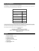
ABOUT YOUR TANKBUDDY™ Congratulations on the purchase of your Eemax TankBuddy™! The TankBuddy™ is a device that extends the usable hot water from your existing hot water storage device, while maintaining the existing electrical power infrastructure. TECHNICAL SPECIFICATIONS Voltage 240 VAC Max Amperage 30 Amps Max Power Rating 7.2 kW Pre-Set Outlet Temperature 120°F Activation Temp Range 80-130°F Outlet Temperature Range 80-140°F Activation Flow Rate 0.
1- BEFORE INSTALLATION PLEASE READ THESE INSTRUCTIONS THOROUGHLY AND COMPLETELY PRIOR TO INSTALLATION & USE. FAILURE TO FOLLOW INSTRUCTIONS COULD CAUSE PROPERTY DAMAGE, SERIOUS PERSONAL INJURY, OR DEATH. By installing this product, you acknowledge the terms of the manufacturer’s warranty. Once the heater is installed, do not return product to the place of purchase. If you have any questions regarding the warranty or product return policies, please contact us at 1-800-543-6163. Inspect all components.
3- SETTING UP TO INSTALL Recommended Clearances: At least 14 inches from above the existing tank heater to the next obstruction 6 inches in front of and to the sides of the TankBuddy™, for service maintenance Pre-Mounting Steps 1. SHUT OFF ELECTRICITY ON YOUR CIRCUIT BREAKER BEFORE PROCEEDING TO ANY FURTHER INSTALLATION STEPS. 2. Make sure there is at least 14 inches of straight pipe clearance above the tank heater.
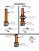
Possible Pre-Existing Plumbing Layouts At least 1 ½” of vertical pipe movement At least 1 ½” of vertical pipe movement Hot Water Copper Pipe Hot Water Copper Pipe Irremovable or essential union (Can be variety of fittings) Hot Water Outlet Connection Fitting (Can be variety of fittings) Hot Water Outlet Connection Fitting (Can be variety of fittings) Layout A At least 14 inches of straight pipe above tank At least 1 ½” of vertical pipe movement (ability to raise pipe) Turn to page 5 No verti
Cutting the Copper Hot Water Pipe – Layout A Please follow all pre-installation instructions carefully. We recommend that this product be installed by a qualified homeowner. If further assistance is needed, a licensed and qualified plumber in accordance with all applicable national, state, provincial, and local plumbing codes should be hired. 1. Locate the hot water outlet connection on your pre-existing water tank.
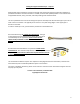
Cutting the Copper Hot Water Pipe – Layout B Please follow all pre-installation instructions carefully. If further assistance is needed, a licensed and qualified plumber in accordance with all applicable national, state, provincial, and local plumbing codes should be hired. 1. Locate the irremovable or essential union on the hot water pipe. On the copper pipe, mark with a pencil 2 inches above the topmost point of the irremovable/essential union. Refer to Figure C. 2.
Cutting the Copper Hot Water Pipe – Layout C Please follow all pre-installation instructions carefully. We recommend that this product be installed by a qualified homeowner. If further assistance is needed, a licensed and qualified plumber in accordance with all applicable national, state, provincial, and local plumbing codes should be hired. This set-up addresses the issue of not having free space to vertically move the hot water pipe up in order to make a secure connection.
4- PLUMBING INSTALLATION Please follow all plumbing instructions carefully. We recommend that this product be installed by a qualified homeowner. If further assistance is needed, a licensed and qualified plumber in accordance with all applicable national, state, provincial, and local plumbing codes should be hired. Plumbing Installation Instructions Please see installation diagrams on the following pages for visual guidance.
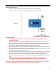
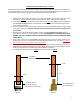
Plumbing Installation Visual Guidance – Layout A Existing Household Plumbing .875”/ ¾ Copper Tube F. Push-to-Connect Fitting E. ½“ Nut D. ½” Ferrule C. ½” Ferrule B. ½“ Nut A.
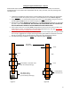
Plumbing Installation Visual Guidance – Layout B Existing Household Plumbing .875”/ ¾ Copper Tube F. Push-to-Connect Fitting E. ½“ Nut D. ½” Ferrule Step 2 C. ½” Ferrule B. ½“ Nut Step 1 F. Push-to-Connect Fitting Existing Household Plumbing .
IMPORTANT NOTES: 1. This unit should not require soldering any pipes for installation. Heat from soldering may damage the flow sensor in the unit. 2. This unit is equipped with both computer-controlled and electro-mechanical auto resetting thermostat switches for high-limited temperature protection. Since this product does not use a storage tank, the use of a temperature pressure relief valve (T&P) is not required for most installations. UL Standard 499 does NOT require that a pressure relief valve be used.
5- ELECTRICAL INSTALLATION We recommend that this product be installed by a qualified homeowner. If further assistance is needed, a licensed and qualified electrician in accordance with all applicable national, state, provincial, and local electrical codes should be hired. As with all electrical appliances, under no circumstances should you attempt to install, repair or disassemble this water heater without first shutting off all power to the unit directly at the fuse or breaker box.
Electrical Wiring Diagram Normal Tank Configuration: TankBuddy™ and Electric Tank Configuration: Connection Reference 1, shown on page 14. Connection Reference 2, shown on page 15.
Connection Reference 1 Connecting Lines 1 & 2 from the circuit board (existing service) to the TankBuddy™: 1. Remove the control knob from the unit, then remove the cover of the unit. Two screws (located on the side of the unit) must be removed in order to do this. 2. For this step, if the leads from the breaker are wrapped in a common household cable jacket, make sure the ends of the leads are exposed from the external jacket for at least 10 inches. Strip back 3/8” to bare copper on L1 & L2.
Connection Reference 2 Connecting the pigtail cord to the TankBuddy™: 1. The pigtail cord should be partially attached to the unit through the ground connection. With the cover off, you should see an exposed red wire and black wire coming from the pigtail, on the end that’s inside the unit. Connect the red wire to the left-most terminal, and the black wire to the right-adjacent terminal. 2. Tighten the connections on the terminal block with a flathead screwdriver.
6- GENERAL OPERATING INSTRUCTIONS Operating your new unit is very similar to using any traditional water heating system. However, it is very important that you carefully read all of the set-up procedures and operating instructions and tips to ensure the maximum performance and energy savings from your new water heater. We recommend that all members of the household read these General Operating Instructions.
The following table represents some of the most common technical support questions we receive. Before calling us, please read thoroughly to see if your question or problem is addressed. PROBLEM POSSIBLE CAUSE SOLUTION Unit is not heating at all (water is flowing but the unit is not heating at all — the outgoing water temperature is the same as my cold water supply) and/or the digital display does NOT light up. No power or incorrect wiring. Make sure the breakers at main electrical panel are ON.
9- USER INTERFACE TankBuddy™ Features List of Menu Options Provided by the Software (Clarified Below and on Following Page): Inlet/Outlet Temperature Reading Active Unit in Operation Activation Temperature Max Temperature Software Version Primary Menu Cycle Screens Turn the control knob in either direction to cycle through menu options. Inlet/Outlet Temperature Reading The temperature of the water going in and out of the TankBuddy™ can be observed from this display.
Active Time The active time screen will display how long the unit has been actively heating water. The time is displayed in HOURS:MINUTES Total Time This screen tells the user the total amount of time the unit has been on in it’s lifespan ACTIVE 1:12 TOTAL 12345:12 Setup If the knob is pressed once on this screen, the user will be taken to all the booster heating set up interface. ALL OF THE FOLLOWING SET UP CYCLE SCREENS WILL ORIGINATE FROM PRESSING THE KNOB ONCE ON THIS DISPLAY.
Software Version Here you can view the heater software version (useful for troubleshooting). Exit If knob is pressed once on this screen, the user will be taken back to the primary menu screen cycle.
Eemax Inc. 400 Captain Neville Drive, Waterbury, CT 06705 Toll Free: 1-800-543-6163, or 203-267-7890 Fax: 203-267-7975 info@eemaxinc.