INSTALLATION GUIDE AND OWNER’S MANUAL FlowCo™ ELECTRIC INSTANTANEOUS WATER HEATERS
BEFORE ATTEMPTING ANY INSTALLATION, MODIFICATION OR SERVICE OF THIS HEATER, MAKE SURE THE ELECTRICAL POWER IS DISCONNECTED. Read and understand the instructions thoroughly before attempting the installation or service of this water heater. Failure to follow the instructions can result in serious injury, death and/or property damage. The warranty of the water heater will depend upon proper installation according to the instructions. Some heaters come supplied with separate faucet aerators.
DO NOT INSTALL IN A BATH ENCLOSURE OR SHOWER STALL OR CONNECT TO A SALTREGENERATED WATER SOFTENER OR A WATER SUPPLY OF SALT WATER. ATTENTION: NE PAS INSTALLER DANS UNE BAIGNOIRE OU UNE CABINE DE DOUCHE ET NE PAS BRANCHER À UN ADOUCISSEUR D’EAU RÉGÉNÉRÉ AVEC DU SEL OU À UN APPROVISIONNEMENT EN EAU SALÉE. (CANADIAN INSTALLATIONS ONLY) CONNECT ONLY TO A CIRCUIT PROTECTED BY A CLASS A GROUND FAULT CIRCUIT INTERRUPTER.
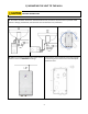
1) MOUNTING THE UNIT TO THE WALL THIS HEATER MUST BE INSTALLED IN A LOCATION WHERE IT IS NOT SUBJECT TO FREEZING TEMPERATURES. 1. The heater should be mounted on the wall under the sink, as close to the point-of-use as possible. Ideal position is fittings pointed down, but the heater can be mounted in any orientation. 2. Make sure to leave a minimum of 8 inches service 3. Remove the cover and fasten to the wall using the clearance at the end OPPOSITE the fittings.
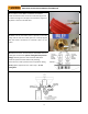
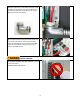
2) PLUMBING HOOK-UP The heater is supplied with 3/8” brass compression fittings that are compatible with either copper or plastic pipes. Make sure these fittings are used for this installation. Contact your Eemax representative for further information. NEVER SUBSTITUTE THREADED PIPE FITTINGS USING PIPE DOPE OR TEFLON TAPE AND NEVER SOLDER ANY PIPE CONNECTIONS WHILE ATTACHED TO THIS HEATER BECAUSE DAMAGE TO THE HEATER WILL RESULT.
BEFORE ATTEMPTING ANY INSTALLATION, MODIFICATION OR SERVICE OF THIS HEATER, MAKE SURE THE ELECTRICAL POWER IS DISCONNECTED. 1. The heater’s water INLET and OUTLET are labeled. Install full flow ball valves to the inlet and outlet pipes and run water through the inlet pipe into a bucket to purge it of any debris. Close the inlet ball valve. 2.
4. Open the hot water faucet and run water for a minimum of 60 seconds and until the flow is continuous and free of air pockets. Close the faucet and install the aerator (if supplied). Failure to install aerator will result in less-than-favorable heater performance.
3) ELECTRICAL HOOK-UP BEFORE BEGINNING ANY WORK ON THIS INSTALLATION, CONFIRM THE ELECTRICAL BREAKER IS “OFF” AND THAT ALL MOUNTING AND PLUMBING WORK HAS BEEN COMPLETED PER THE STATED INSTRUCTIONS. For use on an individual branch circuit only. The heater shall be installed using insulated, UL listed, 2 wire cable (2 wire plus ground) of the appropriate size suitable for up to 75°C and protected by the correctly rated circuit breaker.
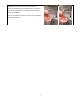
1. Power cable entry to the heater should be made through one of the knock-out holes located on the back plate or top/bottom ends of the unit. Use the appropriate strain relief fitting. 2. The power leads are to be secured to the L1 and L2 or L and N connectors on the terminal block or relay. The ground lead is to be secured to the GND connector on the block or the green ground wire with the provided wire nut. FAILURE TO GROUND THE SYSTEM MAY RESULT IN SERIOUS INJURY, DEATH AND/OR PROPERTY DAMAGE. 3.
4) COMMISSIONING THE HEATER BEFORE SWITCHING THE ELECTRICAL BREAKER “ON”, VERIFY THE INLET AND OUTLET BALL VALVES ARE FULLY OPEN AND WATER IS FLOWING THROUGH THE HOT WATER FAUCET FOR A MINUTE OR TWO UNTIL THE FLOW IS CONTINUOUS AND FREE FROM AIR POCKETS. DO NOT SWITCH THE BREAKER “ON” IF THERE IS A POSSIBILITY THE WATER IN THE HEATER IS FROZEN. 1. Verify water is flowing through the faucet. 2. Switch “ON” the electric power supply at the breaker. 3.
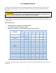
Congratulations! Your Eemax tankless electric water heater is installed and ready for use! MAXIMUM TEMPERATURE RISE AT SPECIFIED FLOW RATE, °F (°C) GPM (LPM) Base 0.2 0.25 0.3 0.4 0.5 0.7 0.8 1.0 1.5 Model* (0.76) (0.95) (1.14) (1.51) (1.89) (2.65) (3.03) (3.79) (5.
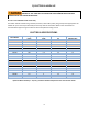
MAXIMUM DERATED TEMPERATURE RISE AT SPECIFIED FLOW RATE, °F (°C) 240VAC heaters used at 208VAC GPM (LPM) Base Model* 0.2 0.25 0.3 0.4 0.5 0.7 0.8 1.0 1.5 (0.76) (0.95) (1.14) (1.51) (1.89) (2.65) (3.03) (3.79) (5.
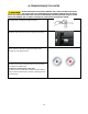
5) TROUBLESHOOTING CAUTION: Make certain power to unit is “OFF” before removing protective cover FOR ANY REASON. For status resolution, please consult the table below.
6) PERIODIC MAINTENANCE The heater is designed for many years of carefree use. In order to maintain consistent water flow, it may be necessary to periodically clean the faucet aerator or the filter screen located in the brass inlet fitting at the heater.
7) REPLACEMENT PART NUMBERS COMPRESSION FITTINGS 3/8" NUT 3/8" SLEEVE EX68B EX68C 8) REPAIR PARTS FOR FLOWCO UNITS Base Model Element Cartridge Control Board Relay SPEX1812 SPEX2412 SPEX3012 SPEX3512 SPEX35 SPEX48 SPEX55 SPEX65 SPEX75 SPEX95 SPEX3208 SPEX4208 SPEX8208 SPEX3277 SPEX4277 SPEX60 SPEX80 SPEX90 SPEX100 EX800 PRT EX610 EX480 EX410 EX1650 EX1200 EX1050 EX890 EX770 EX630 EX1440 EX1050 EX520 EX260 EX1870 EX1280 EX960 EX850 EX760 EX383 EX383 EX383 EX383 EX383 EX383 EX383 EX383 EX383 EX383 EX3
Notes: Eemax Inc., 400 Captain Neville Drive, Waterbury, CT 06705 Tel: 800-543-6163, 203-267-7890, Fax: 203-267-7975, email: support@eemaxinc.