
Install Instructions
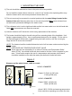
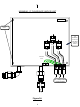
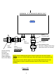
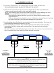
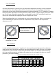
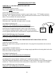
Table Of Contents

II. PLUMBING HOOK-UP
1) The unit is supplied with ¾’’ NPT fittings (Figure 3), USE THESE. DO NOT USE
PIPE DOPE AND DO NOT SOLDER TO THE INLET OR OUTLET.
2) Take care to ensure that the pipes are correctly aligned with the inlet and outlet bosses
in order to avoid excessive stress on the heater body molding.
NOTE: When soldering pipe joints remove heater from the wall. Serious damage can occur
if any soldering is done while pipes are connected to the heater.
When tighten the fittings make sure to secure the fitting inside the heater to make
a tight connection.
Run water through the supply pipe to remove all debris from the pipe before connecting
the heater. Failure to do so could cause damage to the flow switch.
3) Install isolating valves (full flow ball valve type) on both inlet and outlet pipes. This allows unit
to be isolated for maintenance purposes. (Fig. 1B)
4) When all plumbing is complete, fully check the system for water leaks at all the plumbing
connections. If a leak is present take corrective action. Fully open both inlet and outlet
BALL VALVES.
Run all the hot water outlets fed by this heater one at a time, for a minute or two, until the water
flow is continuous, free from “gulping” and from all visible air pockets.
HOT OUTLET
¾’’ NPT
FITTING
DO NOT SOLDER
COLD INLET
¾’’ NPT
FITTING
DO NOT SOLDER
NOTE:
ALL MOUNTING AND PLUMBING MUST BE COMPLETE BEFORE YOU
PROCEED WITH ELECTRICAL HOOK-UP.
TEST THE INSTALLATION FOR LEAKS BEFORE CONNECTING THE
ELECTRICAL SUPPLY.
7”
Figure 3
6