INSTALLATION INSTRUCTIONS & HOME OWNERS MANUAL AUTOBOOSTER™ IMPORTANT SAFETY INFORMATION When installing or using any high voltage electrical appliance, basic safety precautions should always be followed. Under no circumstance should you attempt to clean, install, inspect, repair, disassemble or otherwise service this water heater, without first shutting off all power to the unit directly at the circuit breaker box. SERIOUS BODILY INJURY OR DEATH COULD OCCUR IF YOU IGNORE THIS WARNING.
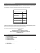
ABOUT YOUR AUTOBOOSTER™ Congratulations on the purchase of your Eemax AutoBooster™! You have purchased an innovative product from the minds of the proven experts at Eemax. The AutoBooster™ increases the deliverable hot water capacity of any tank water heater. TECHNICAL SPECIFICATIONS Voltage 240 VAC Max Amperage 30 Amps Max Power Rating 7.2 kW Pre-Set Outlet Temperature 120°F Activation Temp Range 80-130°F Outlet Temperature Range 80-140°F Activation Flow Rate 0.
1- BEFORE INSTALLATION PLEASE READ THESE INSTRUCTIONS THOROUGHLY AND COMPLETELY PRIOR TO INSTALLATION & USE. FAILURE TO FOLLOW INSTRUCTIONS COULD CAUSE PROPERTY DAMAGE, SERIOUS PERSONAL INJURY, OR DEATH. By installing this product, you acknowledge the terms of the manufacturer’s warranty. Once the heater is installed, do not return product to the place of purchase. If you have any questions regarding the warranty or product return policies, please contact Eemax at 1-800-543-6163. Inspect all components.
3- SETTING UP TO INSTALL Recommended Clearances: 14 inches from above the existing tank heater to the next obstruction 6 inches in front of and to the sides of the AutoBooster™, for service maintenance 14 inches Pre-Mounting Steps 1. SHUT OFF ELECTRICITY ON YOUR CIRCUIT BREAKER BEFORE PROCEEDING TO ANY FURTHER INSTALLATION STEPS. 2. Make sure there is at least 14 inches of straight pipe clearance above the tank heater.
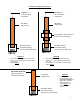
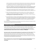
Possible Pre-Existing Plumbing Layouts At least 1 ½” of vertical pipe movement At least 1 ½” of vertical pipe movement Hot Water Copper Pipe Hot Water Copper Pipe Irremovable or essential union (Can be variety of fittings) Hot Water Outlet Connection Fitting (Can be variety of fittings) Hot Water Outlet Connection Fitting (Can be variety of fittings) Layout A At least 14 inches of straight pipe above tank At least 1 ½” of vertical pipe movement (ability to raise pipe) Turn to page 5 No verti
Cutting the Copper Hot Water Pipe – Layout A Please follow all pre-installation instructions carefully. If further assistance is needed, a licensed and qualified plumber in accordance with all applicable national, state, provincial, and local plumbing codes should be hired. 1. Locate the hot water outlet connection on your pre-existing water tank. On the copper pipe, mark with a pencil 2 inches above the topmost point of the hot water outlet connection fitting. 2.
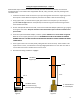
Cutting the Copper Hot Water Pipe – Layout B Please follow all pre-installation instructions carefully. If further assistance is needed, a licensed and qualified plumber in accordance with all applicable national, state, provincial, and local plumbing codes should be hired. 1. Locate the irremovable or essential union on the hot water pipe. On the copper pipe, mark with a pencil 2 inches above the topmost point of the irremovable/essential union. Refer to Figure C. 2.
Customer Service Toll Free: 1-800-543-6163, or 203-267-7890 info@eemaxinc.com 4- PLUMBING INSTALLATION Please follow all plumbing instructions carefully. If further assistance is needed, a licensed and qualified plumber in accordance with all applicable national, state, provincial, and local plumbing codes should be hired.
pressure relief valve in accordance with local codes and ensure that it operates correctly and that air is purged from the valve prior to installing the water heater. When connecting to Flex or High Temperature CPVC pipe, we recommend that a T&P valve be used for added safety. Please note: Installations in the Commonwealth of Massachusetts and State of Kentucky require a pressure relief valve. Please check your local installation codes for any special requirements. 2.
Installation Instructions STEP 1: Making sure all electrical power is shut off, remove the black, red, and ground wires from the existing tank heater coming from the circuit breaker. These wires will now go into the AutoBooster™ through the hole in the unit’s back plate (see Electrical Wiring Diagram on page 10 and Connection Reference 1 on page 11.
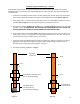
Electrical Wiring Diagram Normal Tank Configuration: AutoBooster™ and Electric Tank Configuration: Connection Reference 1, shown on page 11. Connection Reference 2, shown on page 12.
Connection Reference 1 Connecting Lines 1 & 2 from the circuit board (existing service) to the AutoBooster™: 1. Remove the control knob from the unit, then remove the cover of the unit. Two screws must be removed in order to do this. 2. For this step, if the leads from the breaker are wrapped in a common household cable jacket, make sure the ends of the leads are exposed from the external jacket at least 10 inches. Strip back ⅜” to bare copper on L1 and L2.
Connection Reference 2 Connecting the pigtail cord to the AutoBooster™: 1. The pigtail cord should be partially attached to the unit through the ground connection. With the cover off, you should see an exposed red wire and black wire coming from the pigtail, on the end that’s inside the unit. Connect the red wire to the left-most terminal, and the black wire to the right-adjacent terminal. 2. Tighten the connections on the terminal block with a flathead screwdriver.
6- GENERAL OPERATING INSTRUCTIONS Operating your new unit is very similar to using any traditional water heating system. However, it is very important that you carefully read all of the set-up procedures and operating instructions and tips to ensure the maximum performance and energy savings from your new water heater. We recommend that all members of the household read these General Operating Instructions.
The following table represents some of the most common technical support questions we receive. Before calling us, please read thoroughly to see if your question or problem is addressed. PROBLEM POSSIBLE CAUSE SOLUTION Unit is not heating at all (water is Make sure the breakers at main electrical panel are ON. You may have a faulty flowing but the unit is not heating No power or incorrect wiring. breaker or unit may be wired incorrect. Refer to page 13 for proper wiring at all — the outgoing water layout.
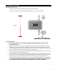
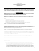
9- USER INTERFACE AutoBooster™ Features List of Menu Options Provided by the Software (Clarified Below and on Following Page): Inlet/Outlet Temperature Reading Active Unit in Operation Activation Temperature Max Temperature Software Version Eco Mode Vacation Mode Freeze Protect Primary Menu Cycle Screens Turn the control knob in either direction to cycle through menu options.
Active Time The active time screen will display how long the unit has been actively heating water. The time is displayed in HOURS:MINUTES Total Time This screen tells the user the total amount of time the unit has been on in it’s lifespan ACTIVE 1:12 TOTAL 12345:12 Setup If the knob is pressed once on this screen, the user will be taken to all the booster heating set up interface. ALL OF THE FOLLOWING SET UP CYCLE SCREENS WILL ORIGINATE FROM PRESSING THE KNOB ONCE ON THIS DISPLAY.
Vacation Mode (Select Models Only) Vacation mode will shut down the heater while you go away on vacation. To change this setting, press the knob once, and a “*” will appear on screen. Turn the knob to adjust ON/OFF, and then press the knob again to save the setting. Note, freeze protect feature will override vacation mode. Eco Mode Eco mode will turn the tank off and on at specific times of the day, set by the user, in order to conserve energy.
Eemax Inc. 400 Captain Neville Drive, Waterbury, CT 06705 Toll Free: 1-800-543-6163, or 203-267-7890 Fax: 203-267-7975 info@eemaxinc.