
Installation Sheet

EX07200-121 Rev A
Manufacturer’s National Service Department | 400 Captain Neville Dr. Waterbury, CT 06705
Eemax® 800-543-6163 | EcoSmart® 877-474-6473 | Rheem® or Richmond® 800-374-8806
Information contained in this document is subject to change without notice.
7
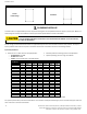
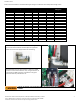
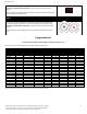
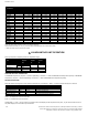
Refer to the chart below for recommended copper wiring for conductors with a temperature rating of 75°C:
FlowCo
LavAdvantage
AccuMix II
Voltage
Max power
Max current
Minimum wire size
(AWG) @75°C
(VAC)
(kW)
(A)
SPEX1812
SPEX1812T
-
120
1.8
15
14
SPEX2412
SPEX2412T
-
120
2.4
20
14
SPEX3012
SPEX3012T
-
120
3
25
12
SPEX3512
SPEX3512T
AM004120T
120
3.5
29
10
SPEX35
SPEX35T
-
240
3.5
15
14
SPEX48
SPEX48T
AM005240T
240
4.8
20
14
SPEX55
SPEX55T
-
240
5.5
23
12
SPEX65
SPEX65T
AM007240T
240
6.5
27
10
SPEX75
SPEX75T
-
240
7.5
32
10
SPEX95
SPEX95T
AM010240T
240
9.5
40
8
-
SPEX012240T
AM012240T
240
11.5
48
8
SPEX3208
SPEX3208T
-
208
3
15
14
SPEX4208
SPEX4208T
-
208
4.1
20
14
SPEX8208
SPEX8208T
-
208
8.3
40
8
SPEX3277
SPEX3277T
-
277
3
11
14
SPEX4277
SPEX4277T
AM004277T
277
4.1
14.8
14
SPEX60
SPEX60T
-
277
6
22
12
SPEX80
SPEX80T
AM008277T
277
8
29
10
SPEX90
SPEX90T
-
277
9
33
10
SPEX100
SPEX100T
AM010277T
277
10
36
8
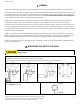
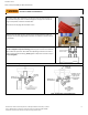
Power cable entry to the heater should be made through one of
the knock-out holes located on the back plate or top/bottom
ends of the unit. Use the appropriate strain relief fitting.
The power leads are to be secured to the L1 and L2 or L and N
connectors on the terminal block or relay. The ground lead is to
be secured to the GND connector on the block or the green
ground wire with the provided wire nut.
FAILURE TO GROUND THE SYSTEM MAY RESULT IN SERIOUS INJURY, DEATH AND/OR PROPERTY
DAMAGE.