INSTALLATION, OPERATION, AND MAINTENANCE MANUAL FOR TANKLESS ELECTRIC WATER HEATERS PROSERIES XTP™
IMPORTANT SAFETY INFORMATION READ ALL INSTRUCTIONS BEFORE USING DANGER Indicates an imminently hazardous situation which, if not avoided, will result in death or serious injury. WARNING Indicates a potentially hazardous situation which, if not avoided, could result in death or serious injury. CAUTION Indicates a potentially hazardous situation which, if not avoided, may result in minor or moderate injury. Hot water can be dangerous. There is a high scald potential if the thermostat is set too high.
IMPORTANT SAFETY INFORMATION READ ALL INSTRUCTIONS BEFORE USING 1. You must read and follow all instructions. Serious bodily injury or death could occur if you ignore this warning. 2. 3. 4. 5. 6. 7. Per UL 499, this water heater is not required to be installed with a Temperature and Pressure relief valve (T&P). However, local codes may vary.
IMPORTANT SAFETY INFORMATION READ ALL INSTRUCTIONS BEFORE USING 10.When the heater is installed in a well 14.This heater must be installed in a water system or if the plumbing location where it is not subject to system is prone to introducing air into freezing temperatures unless supplied the heater, it is highly recommended with factory installed freeze that an air separator be installed in the protection. cold water feed to the heater to avoid possible failure of the heating element 15.
IMPORTANT SAFETY INFORMATION READ ALL INSTRUCTIONS BEFORE USING 17.Applications with the use of a circulating pump recirculation circulator must be installed according schematics. 18. Should applications call for the use of antifreeze. A mixture of Propylene Glycol is the only recommended antifreeze. The use of Ethylene glycol antifreeze is strictly prohibited. TABLE OF CONTENTS TABLE OF CONTENTS ...............................................................................................................
ABOUT YOUR PROSERIES XTP Congratulations on the purchase of ProSeries XTP! Read all set-up procedures and operating instructions carefully to ensure maximum performance and energy savings from the water heater. It is important that the heater be installed in accordance with stated instructions and the electrical and plumbing codes applicable to your area. Read this manual thoroughly for important operating instructions and tips.
BEFORE INSTALLATION READ THESE INSTRUCTIONS THOROUGHLY AND COMPLETELY PRIOR TO INSTALLATION & USE. FAILURE TO FOLLOW INSTRUCTIONS COULD CAUSE PROPERTY DAMAGE, SERIOUS PERSONAL INJURY, OR DEATH. By installing this product, you acknowledge the terms of the manufacturer’s warranty. Once the heater is installed, do not return product to the place of purchase.
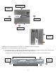
10" Top Clearance Upright Installation \ 8" Clearance 8" Clearance 18" Clearance Alternate Installation ProSeries XTP models are approved for zero clearance to combustible surfaces such as plywood. Above clearances are recommended for service and installation. 1. Locate the best position to mount the unit. Check clearances around the unit according to the diagram below. Measure from the top, bottom, left & right sides of the bracket to ensure proper clearances.
2. Remove the locking screw from the center of the slide lock bracket (to be used in step 8) 3. Hang the unit on the bracket by aligning the left edge of the enclosure with the alignment mark on the wall bracket and the top edge of the wall bracket with the top edge of the alignment label on the front cover. 3 4. Slide the unit down onto the bracket until it stops, indicating that the wall bracket is holding the weight of the unit. 5. Slide the unit to the left to until it stops.
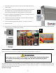
Before starting any electrical work: VERIFY there is no power at the heater The field wiring power conductors are to be secured to the L1, L2 and L3 connectors on the contactor(Fig. 1) .The ground is to be secured to the GND connector to the left of the contactor. Fig. 1 GND L1 L2 L3 WARNING Failure to ground the system may result in death, serious injury, and/or property damage.
PLUMBING HOOKUP Must flush line a minimum 2 minutes, at a maximum flow on initial start-up. Reference the recommended installation diagram below. Additional installation diagrams for recirculation loops, multiple ProSeries XTP units plumbed in series or parallel configurations, can be found in the APPLICATION SCHEMATICS section of this manual. The heater is equipped with brass ¾” NPT fittings. Make sure ONLY NPT fittings are used for connection to this heater.
WARNING Must flush out water heater for minimum 2 minutes at maximum flow on initial start-up or after any service work has been performed. Close and open drain valve 3 times to remove any lodged air bubbles. Failure to do so may damage the heater. Minimum inlet water pressure 35 psi dynamic. Maximum water pressure not to exceed 150 psi. Recommended operating pressure is 35 psi. Use of a pressure regulator recommended.
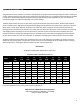
Proper water conditions must be maintained to prevent damage to the water heater. MAXIMUM ALLOWABLE CONCENTRATION BETTER BEST Alkalinity 50 25 10 Calcium 25 5 0.5 Carbon Dioxide 0 0 0 100 15 1 1 1 0.05 Iron 0.2 0.1 0.01 Magnesium as Mg 0.5 0.1 0.1 Magnesium as Mn 0.1 0.1 0.1 Nitrate 25 25 10 Oxygen 2 1 0.1 Silica 15 10 1 Sodium 50 10 1 Sulfate 25 25 1 Total Dissolved Solids (TDS)* 200 100 5** Total Hardness 25 10 1 6.5 – 8.5 6.5 – 8.5 6.5 – 8.
COMMISSIONING THE WATER HEATER CAUTION Before switching the electrical breaker "on", make sure the inlet and outlet ball valves are fully open and water is flowing through all points of use for a minimum of 2 minutes at maximum flow. Open and close drain valve 3 times while purging to remove any lodged air bubbles. Do not switch the breaker "on" if there is any possibility the water in the heater is frozen.
Navigating the menus: Tap the left ESC button to move to the main menu screen. Diagram 1 contains a flow chart of all of the sub-menus that are accessible and which keys to press in order to navigate to each menu. To return to the “Run” screen: hold the ESC key at any time for 3 seconds or tap the ESC key until the run screen is displayed.
SOFTWARE FEATURES Notifications: Code B005 Name Inlet thermistor disconnected C010 B015 Outlet thermistor disconnected Inlet AND outlet thermistors disconnected Current transformer disconnected B050 C070 B080 B083 B086 A090 Channel 1 element outside tolerance, LOW kW rating Channel 2 element outside tolerance, LOW kW rating Channel 3 element outside tolerance, LOW kW rating Channel 1 element outside tolerance, LOW kW rating Channel 2 element outside tolerance, LOW kW rating Channel 3 element outside
Parameters: Code P000 Name Inlet override P005 Setpoint tuning P030 Activation flow P045 Activation delay P050 Delay contactor off P051 Delay display off P060 Units selection Details Overrides inlet temperature in case of an inlet thermistor missing. Allows user to fine tune outlet temperature to match the setpoint. Minimum flow required to enable heating. Time between flow above activation threshold and heating enabled. Time between flow below activation threshold and contactor disengaging.
START-UP PROCESS Plumbing installation checklist must be filled out and left with water heater. Must flush water heater for 2 minutes at a minimum. Eemax installation checklist and start-up procedure for ProSeries XTP water heaters Important - Read and fully understand all steps outlined below before proceeding. Failure to do so may damage the water heater and void any warranty.
Important - Read and fully understand all steps outlined below before proceeding. Failure to do so may damage the water heater and void any warranty.
Shutdown Process (Normal, Emergency, and Long Term) Shut down procedure Important - Read and fully understand all steps outlined below before proceeding. Failure to do so may damage the water heater and void any warranty.
MONITORING & PREVENTIVE MAINTENANCE Recommended routine instrument readings and operation checking: Please note the instrument readings are performed during water heater operation. No readings are required when the unit is not being used.
TECHNICAL SUPPORT TECHNICAL SUPPORT FORM PERFORM STEPS BELOW BEFORE CALLING TECHNICAL SUPPORT WATER HEATER MODEL # ____________________________________ SERIAL # ____________________________________ Inlet Water Pressure ____________________ Inlet Water Temperature ____________________ Notifications ______________________________________________________________________________________________ ______________________________________________________________________________________________ Incoming Voltag
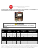
ECO Testing Points Test ECO’s (electric cut offs): To check all ECO’S simultaneously measure from COMMON TEST POINT to 3 CHAMBER (or 6 CHAMBER) for continuity. If no continuity, then check across each ECO individually. ECO’s may be manually reset after they have cooled. Run cold water and press the stem to reset. Water may need to run for a few minutes. Check continuity to confirm a reset ECO.
APPLICATIONS SCHEMATICS 23
24
25
26
27
28
29
30
31
32
33
34
35
36
REPAIRS Repair Parts WARNING Service and repairs are to be performed by licensed electricians or qualified servicemen. WARNING Before attempting any repairs to the heater, make sure that the electrical breaker is “off” and confirm that there is no voltage at the heater.
Repair Parts (continued) 45 Model Number Element Number Assembly XTP018208 EX05502-00 EX76042-02 EX09100-01 EX08303-07 XTP024208 EX05502-01 EX76042-02 EX09100-01 EX08303-07 XTP032208 EX05502-02 EX76042-02 EX09100-01 EX08303-07 XTP016480 EX05502-03 EX76042-02 EX09100-01 EX08303-08 XTP020480 EX05502-04 EX76042-02 EX09100-01 EX08303-08 XTP024480 EX05502-05 EX76042-02 EX09100-01 EX08303-08 XTP027480 EX05502-06 EX76042-02 EX09100-01 EX08303-08 XTP036480 EX05502-07 EX76042-02 EX09100-01
WIRING SCHEMATICS XTP016480-027480 & XTP018208-024208 WIRING SCHEMATIC 39
XTP036480-054480 & XTP032208 WIRING SCHEMATIC EX07200-89 REV A 40
USA AND CANADA: Eemax Inc. 400 Captain Neville Drive, Waterbury, CT 06705 Toll Free: 1-800-543-6163, or 203-267-7890 Fax: 203-267-7975 Eemax.Support@eemax.