
Installation Guide and Manual


9
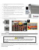
Before starting any electrical work: VERIFY there is
no power at the heater
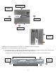
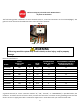
The field wiring power conductors are to be secured to the L1, L2 and L3 connectors on the contactor(Fig. 1) .The
ground is to be secured to the GND connector to the left of the contactor.
Fig. 1
WARNING
Failure to ground the system may result in death, serious injury, and/or property
damage.
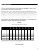
Electrical specifications
MODEL
VOLTS
THREE PHASE
DELTA
KW
TOTAL
AMPS
RECOMMENDED
WIRE SIZE (CU)
90° C
RECOMMENDED MINIMUM
BREAKER SIZE (PER NEC –
INTERMITTENT DUTY)
XTP016480
480
16
20
14
20
XTP020480
480
20
25
12
25
XTP024480
480
24
29
10
35
XTP027480
480
27
33
10
35
XTP036480
480
36
44
8
50
XTP048480
480
48
58
6
60
XTP054480
480
54
65.0
4
70
XTP018208
208
18
50.0
8
50
XTP024208
208
24
67
4
80
XTP032208
208
31.2
87
3
100
A ground terminal (or a wire connector marked "G", "GR”, "Ground", or "GROUNDING") is provided within the
enclosure. To reduce the risk of electric shock, connect this terminal or connector to the grounding terminal of the
electric service or supply panel with a continuous copper wire in accordance with your local electrical code.
GND L1 L2 L3