ROTO-VENT for SERIES 401, 402, 403 storefront Installation Instructions Part NO.
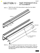
SECTION I GENERAL NOTES II PARTS IDENTIFICATION III APPLICATION BY SYSTEM PAGE 1 PAGE 2 PAGES 3 & 4 IV LOCATING & DRILLING TEMPLATE PAGES 5 & 6 V PAGES 7 - 11 PART PREPARATION & ATTACHMENT VI SIZING FORMULAS PAGE 12 VII TUBE REPLACEMENT PAGE 13 The rotating ventilator is fabricated from 3 1/2" PVC tubing. The ventilating slots are 5 1/2" x 1" and the number of slots vary with the length of the tube.
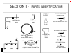
SECTION II - PARTS INDENTIFICATION SETTING BLOCKS JAMB FASTENERS (SCREW SPLINE) [1] MEETING RAIL RETAINER #9952 #9953 [2] S108 #8x1" HEX WASHER HEAD S.M.S. H162 (S-401) [2] RETAINER FASTENERS [1] [1] H190(60-229) (S-402 & S-403) VENT TUBE ASSEMBLY 700-10 (43-019, 43-020, 43-021) STD3 S100 [1] STD3 (EXT. 9955) SHEAR BLOCK SILL #9959 STK0 #8 x 3/4" P.H.
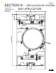
PAGE 3 SECTION III - S401 APPLICATION 3/4" 9129 9129 H162 Shear block attachment shown. Screw spline is similar.
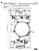
PAGE 4 SECTION III - 1 3/16" Shear block attachment shown. Screw spline is similar.
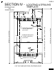
PAGE 5 SECTION IV SCREW SPLINE OR SHEAR BLOCK LOCATING & DRILLING TEMPLATE 9229 1.508 9129 1.070 .250 1.047 5.500 9952 SCREW SPLINE HOLES .172 DIA. (#18 DRILL) (5) PLACES .875 2.750 .875 9959 .250 SHEAR BLOCK HOLES CUT OUT AND USE FOR LOCATING HOLES EXTERIOR - 402/403 SYSTEMS INTERIOR - 401 SYSTEM SHEAR BLOCK HOLES .136 DIA.
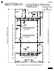
PAGE 6 SECTION IV - LOCATING & DRILLING TEMPLATE SCREW SPLINE OR SHEAR BLOCK 9229 1.508 9129 1.070 .250 1.047 9952 SHEAR BLOCK HOLES .136 DIA. (#29 DRILL) (4) PLACES SCREW SPLINE HOLES .172 DIA. (#18 DRILL) (5) PLACES .875 2.750 5.500 .875 9959 .
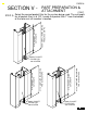
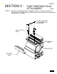
PAGE 7 SECTION V - PART PREPARATION & ATTACHMENT STEP 1) Notch the ends of the tube retainer to clear the shear block during installation. INTERIOR 1.313 EXPOSED 9953 EXTERIOR 1/4" dia. weep holes at 1/4 points. 9959 STEP 2) Drill 1/4" diameter weep holes flush with the interior surface of the sill member. Locate weep holes at quarter points. Take care to protect the exposed surface of the sill member when drilling the weep holes.
PAGE 8 SECTION V - PART PREPARATION & ATTACHMENT CONT. 8.000" SIGHTLINE INCLUDING THE GLASS STOPS STEP 3) Select the correct pocket filler for the system being used. The cut length for all pocket fillers is 6 1/8". Locate the pocket filler 1" from the bottom of the roto-vent sill member’s location.
PAGE 9 SECTION V - PART PREPARATION & ATTACHMENT CONT. STEP 4) Pre-drill the meeting rail with a #18 drill (.170 dia.) 2" from the ends and 16" on center. The TEK screws (STK0) will be used to attach the tube retainer after the unit is installed. .170 DIA. THRU DRILL 2" FROM END & 16" ON CENTERS #8x1" P.H.
PAGE 10 SECTION V - PART PREPARATION & ATTACHMENT CONT. SHEAR BLOCK ATTACHMENT METHOD STEP 5) Determine the location of the roto-vent. Mark the layout of the shear block attachment screws using the template provided with these instructions. STEP 6) Drill through the meeting rail accurately at 1" from the ends and in the locating groove using a #18 drill (.170 dia.).
PAGE 11 SECTION V - PART PREPARATION & ATTACHMENT CONT. SCREW SPLINE ATTACHMENT METHOD STEP 5) Determine the location of the roto-vent. Mark the layout of the screw spline attachment screws using the template provided with these instructions. STEP 6) Drill through the open back verticals with a #18 drill (.170 dia.). #18 drill thru (.170 dia.) clear hole for S-100 (#8 x 1" SL.HW.SMS.
PAGE 12 SECTION VI - SIZING FORMULAS The overall length of the roto-vent assembly equals daylite opening, in all systems. The height of the roto-vent is different between 401 and 402/403. This is due to the different heights of the glass stops. Refer to the illustration below and pages #3 and #4 for the correct dimensions per system. LENGTH = DAYLITE OPENING [401 STSTEM] 8" INCLUDING GLASS STOPS 8.438" INCLUDING GLASS STOPS 402/403 SYSTEMS ] VENT DAYLITE LENGTH = OPENING MINUS .
PAGE 13 SECTION VII - TUBE REPLACEMENT Follow steps 1 through 4 below for roto-vent tube replacement. Order the replacement tube completely fabricated from the factory. The length of the replacement tube is daylite opening minus 3/16". STEP 2 Remove the retainer screws. (STK0) STEP 1 Remove the glazing gasket and the interior glass stop. EXTERIOR SIDE STEP 3 Remove tube retainer (#9953) STEP 4 Slide tube toward the interior to remove for replacement.