SERIES 401, 402, 403 storefront Installation Instructions Part NO.
Series 401,402, & 403 Installation Instructions TABLE OF CONTENTS PAGE SECTION I. General Notes…………………………………….……………………………………………………………..…………. 3 II. Parts Identification Charts……………………………………..………………………………………………….……… 4-30 A. S401 Parts Identification B. S402 Parts Identification C. S403 Parts Identification III. Fabrication and Assembly A. Screw Spline Fabrication…………..…….…………………………………………………………………..….….. 31-36 B. Shear Block Fabrication………….………………….….………….…………………………..………………..… 37-45 C.
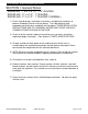
Series 401,402, & 403 Installation Instructions SECTION I: General Notes SERIES 401 - 1 3/4" x 4 1/2" - 1/4" GLAZING SERIES 402 - 2" x 4 1/2" - 1" GLAZING SERIES 403 - 2" x 4 1/2" - 1" GLAZING (THERMAL) 1) Check shop drawings, installation instructions, and glazing instructions to become thoroughly familiar with the project. The shop drawings take precedence for extrusions and details on the project.
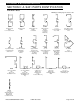
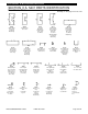
Series 401,402, & 403 Installation Instructions SECTION II: A. S401 PARTS IDENTIFICATION Vertical Parts: Drawings on this page are not to scale. 9102 8681 9103 9104 9117 9120 Tubular Vertical Mullion For L100 Steel Reinf.
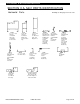
Series 401,402, & 403 Installation Instructions SECTION II: A. S401 PARTS IDENTIFICATION Horizontal Parts: 9148 4 ½” x 4 ½” Side Lite Base Use W/9129 Glass Stop. Use W/9121, 9146 or 9149 1G14 4 ½” Deep Adjustable Side Lite Base Vertical W/BRK. MTL. Use W/1G13 Horizontal Drawings on this page are not to scale.
Series 401,402, & 403 Installation Instructions SECTION II: A. S401 PARTS IDENTIFICATION Door Frame Parts: Drawings on this page are not to scale.
Series 401,402, & 403 Installation Instructions SECTION II: A. S401 PARTS IDENTIFICATION Door Frame Parts: Drawings on this page are not to scale. 9144 9153 4437 4438 Applied ¾” Door Stop Applied Door Stop Applied 5/8” Stop Used At Door Header Only Mates W/9155 5/8” Snap-in Door Stop at Door Header Only Used W/1 ¾” Door EFCO CORPORATION 1/2013 PART NO.
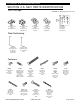
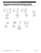
Series 401,402, & 403 Installation Instructions SECTION II: A. S401 PARTS IDENTIFICATION Shear Blocks & Clips: Drawings on this page are not to scale. K120 K122 K123 K124 K126 ( CLR & BRZ ) Door Header Shear Block Pkg. Screws Included Horizontal Intermediate Shear Block Pkg. Screws Included High Side Lite Shear Block Pkg. Screws Included ( CLR. & BRZ. ) Threshold Clip Pkg. O.P. Butt H Screws Included C.O.C. Threshold Clip Pkg.
Series 401,402, & 403 Installation Instructions SECTION II: A. S401 PARTS IDENTIFICATION S401 Drill Jigs: Drawings on this page are not to scale.
Series 401,402, & 403 Installation Instructions SECTION II: A. S401 PARTS IDENTIFICATION Gasket: Drawings on this page are not to scale.
Series 401,402, & 403 Installation Instructions SECTION II: B. S402 PARTS IDENTIFICATION Vertical Parts: Drawings on this page are not to scale. 9204 9202 Vertical Mullion 9203 9204 9220 9212 Female Expansion Mullion Use W/ 9204 Male Expansion Mullion Use W/ 9203 Use W104 Weathering Open Back Vert Use 9221, 9222, or 9246/FS93 Peri.
Series 401,402, & 403 Installation Instructions SECTION II: B. S402 PARTS IDENTIFICATION Horizontal Parts: Drawings on this page are not to scale. 9236 9245 9247 9248 Tubular Side Lite Horizontal Use W/ 9229 Glass Stop Head Use W/ 9246 Adaptor Open Back Sill or Horizontal Use W/ 9229 Glass Stop 9246 adaptors 4 ½” x 4 ½” Side Lite Base Use W/ 9229 Glass Stop 9246 or 9221 Adaptors or Use 9149 Anchor 9268 9149 9270 9160 Open Back Head for Round Tops Use W/ 9269 Glass Stop FS93 Peri. Adpt.
Series 401,402, & 403 Installation Instructions SECTION II: B. S402 PARTS IDENTIFICATION Door Frame Parts: Drawings on this page are not to scale.
Series 401,402, & 403 Installation Instructions SECTION II: B. S402 PARTS IDENTIFICATION Misc. Parts: Drawings on this page are not to scale. 9161 1G13 1G14 9246 FS93 Adjustable Side Lite Base Vertical W/ BRK. MTL. Use W/ 9160 Adjustable Side Lite Base Horizontal W/ BRK. MTL. Use 1G14 Use 9229 Glass Stop Use W104 Weathering Adjustable Side Lite Base Vertical W/ BRK. MTL.
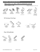
Series 401,402, & 403 Installation Instructions SECTION II: B. S402 PARTS IDENTIFICATION Misc. Parts: Drawings on this page are not to scale. 9938 8643 1G15 Shadowline Window Adaptor Equal Leg Use W104 Weathering System II Window Adaptor Equal Leg Use W104 Weathering Horiz. / Vert. Stack Adaptor 4” Sightline 1G69 1G68 8741 Horiz. / Vert. Stack Adaptor 2” Sightline Horiz. / Vert.
Series 401,402, & 403 Installation Instructions SECTION II: B. S402 PARTS IDENTIFICATION Sill Flashing & End Caps Drawings on this page are not to scale. 9947 8433 1G85 High Performance Lite Sill Flashing Standard High Performance Sill Flashing Use K449 End Cap High Performance Sill Flashing W/ Stool Clip Uses K448 End Cap K449 F098 K293 K292 End Cap Pkg. for #8433 Sill Flashing (1) FT34 (2) STC7 3” Flashing Clip 2 per DLO Use W/ 9957 Sill Flashing Splice ( STD.) Sill Flashing Splice ( OPT.
Series 401,402, & 403 Installation Instructions SECTION II: B. S402 PARTS IDENTIFICATION Shear Blocks & Drill Jigs K124 (clr) K125 (brz) O.P. & Butt Hinge Screws Included Drawing on this page are not to scale K129 (clr) K130 (brz) K126 C.O.C. Threshold Clip Pkg. Screws Included K173 Horizontal Shear Block Pkg. Screws Included Use W/ 9236, 9247 or 9248 Header Shear Block Pkg.Screws Included K358 KN92 KN93 H.D. Horizontal Shear Block Pkg.
Series 401,402, & 403 Installation Instructions SECTION II: B. S402 PARTS IDENTIFICATION Setting Blocks & Steel: Drawings on this page are not to scale. HNA3 HN92 HNA4 Transom Setting Block 1” Glazing Inside Glazed Horizontal Setting Block Inside Glazed Setting Block at Sill HN32 H190 K354 Exterior Glazed Setting Block / Chair Assembly Pkg. at Sill 2” Transom Bar & 2 ½” Side Lite Base Setting Block Pkg. Using 9253 Glass Stop 1” Glass Setting Block Pkg. for 1G13 / 1G14 Adj.
Series 401,402, & 403 Installation Instructions SECTION II:B.
Series 401,402, & 403 Installation Instructions SECTION II: B. S402 PARTS IDENTIFICATION Gasket: Drawings on this page are not to scale.
Series 401,402, & 403 Installation Instructions SECTION II: C. S403 PARTS IDENTIFICATION Vertical Parts: Drawings on this page are not to scale.
Series 401,402, & 403 Installation Instructions SECTION II: C. S403 PARTS IDENTIFICATION Horizontal Parts: Drawings on this page are not to scale.
Series 401,402, & 403 Installation Instructions SECTION II: C. S403 PARTS IDENTIFICATION Door Frame Parts: Drawings on this page are not to scale.
Series 401,402, & 403 Installation Instructions SECTION II: C. S403 PARTS IDENTIFICATION Misc. Parts: Drawings on this page are not to scale. 1G13 1G14 4420 FU99 Adjustable Side Lite Base Horizontal W/ BRK. MTL. Use W/ 1G14 Use 9229 Glass Stop Use W104 Weathering Adjustable Side Lite Base Vertical W/ BRK. MTL.
Series 401,402, & 403 Installation Instructions SECTION II: C. S403 PARTS IDENTIFICATION Misc. Parts: Drawings on this page are not to scale. 16C7 16C8 16C9 2-Part Mullion Half 2-Part Perimeter Interior Half 2-Part Perimeter Exterior Half L100 Tubular Mull Reinforcing Steel Use W/ 9208 & 9209 EFCO CORPORATION 1/2013 PART NO.
Series 401,402, & 403 Installation Instructions SECTION II: C. S403 PARTS IDENTIFICATION Sill Flashing & End Caps: Drawings on this page are not to scale. 1G64 1G65 1G85 High Performance Sill Flashing Use F098 Clip High Performance Sill Flashing High Performance Sill Flashing W/ Stool Clip Use K448 End Cap F098 K448 K293 HWD1 3” Flashing Clip 2 per DLO Use W/1G64 End Cap Pkg. for 1G64, 1G65 & 1G85. (1)FT33 (2)STC6 Sill Flashing Splice (STD.) Water Deflector @ Int.
Series 401,402, & 403 Installation Instructions SECTION II: C. S403 PARTS IDENTIFICATION Shear Blocks & Drill Jigs: K129 (clr) K130 (brz) Header Shear Block Pkg. Screws Included Drawings on this page are not to scale. K172 KN92 Horizontal Shear Block Pkg. Screws Included Use W/ 9336, 9347 & 1G80 402 / 403 2-Piece Rolled Head Shear Block Package K124 (clr) K125 (brz) K153 (clr) K154 (brz) Threshold Clip Pkg. O.P. & Butt H. Screws Included Threshold Clip Pkg. for Conc.
Series 401,402, & 403 Installation Instructions SECTION II: C. S403 PARTS IDENTIFICATION Setting Blocks: Drawings on this page are not to scale. HNA3 HN32 HN92 Transom Setting Block 1” Glazing Exterior Glazed Setting Block / Chair Assembly Pkg. at Sill & Horiz. Inside Glazed Horizontal Setting Block HNA4 H190 K354 Inside Glazed Setting Block At Sill Transom Setting Block Pkg. Using 9253 Glass Stop 1” Glass Setting Block Pkg. for 1G13/1G14 Adj.
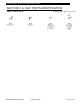
Series 401,402, & 403 Installation Instructions SECTION II: C. S403 PARTS IDENTIFICATION Fasteners: STB9 Horizontal to Shear Block Screw #12 ½”-RHSMS “A” Drawings on this page are not to scale. S101 (clr) S103 (brz) Horizontal to Shear Block Screw @ Head #12 3/4” FHSMS “A” STT7 STU5 M109 Adjustable Side Lite Base Vertical Attachment #10-12 x 1” PHSMS Adjustable Side Lite Base Vert.
Series 401,402, & 403 Installation Instructions Section II: C. S403 PARTS IDENTIFICATION Gaskets & Antiwalk Block: Drawings on this page are not to Scale.
Series 401,402, & 403 Installation Instructions SECTION III: A. SCREW SPLINE FABRICATION The screw spline system is a fabrication and erection method that permits the preassembly of single units in the shop or at the job site. These units are then erected by mating the male mullion with the female mullion counterpart. When an entrance is required, screw spline joinery may be used with the screw spline door jambs only. Otherwise, shear block joinery must be used to attach the side lite horizontals.
Series 401,402, & 403 Installation Instructions SECTION III: A. SCREW SPLINE FABRICATION . gs t ntal win . a h zo r a s otc hori op d ation n his f the he sh al loc t t nt gn o Ali e top ence rizo th efer e ho R r th fo Vertical Member Drill Jig H382 - for 401 H381 - 402/403 FIG. # 1 Place jig on vertical, aligning "V" notches w/ top of horizontal measurement (i.e., sill, intermediate, head, etc.) and then snug up the clamp. USE THIS SECTION FOR SCREW SPLINE PREP JIG:H382 401 FIG.
Series 401,402, & 403 Installation Instructions SECTION III: A. SCREW SPLINE FABRICATION ECONOMY DRILL GUIDES H-701 DRILL GUIDE (401) for SCREW SPLINE APPLICATION Use this edge or the opposite edge for locating the drill guide at the top of the horizontal. (FOR 401 SYSTEM) # 9 drill (.196 dia.), (8) holes are located. Refer to the horizontal extrusion being used to determine the correct holes to drill for the application at head, intermediate, or sill.
Series 401,402, & 403 Installation Instructions SECTION III: A. SCREW SPLINE FABRICATION ECONOMY DRILL GUIDES H-702 DRILL GUIDE (402/403) for SCREW SPLINE APPLICATION Use the top edge of the drill guide to locate the hole pattern for the screw splines. (FOR 402/403 SYSTEM) # 9 drill (.196 dia.), (8) holes are located. Refer to the horizontal extrusion being used to determine the correct holes to drill for the application at head, intermediate, sill, or side lite base.
Series 401,402, & 403 Installation Instructions SECTION III: A. SCREW SPLINE FABRICATION SYSTEM 401 1 3/4" X 4 1/2" SYSTEM 402 & 403 2" X 4 1/2" CAUTION: Door jambs must run to the floor and are cut longer than other verticals. Add sill flashing thickness and/or side lite sill blocking thickness to screw spline mounting hole height location at the sill.
Series 401,402, & 403 Installation Instructions SECTION III: A. SCREW SPLINE FABRICATION REVIEW THE GENERAL NOTES ON PAGE 3 BEFORE PROCEEDING. STEP 1) Apply butyl sealant (S.M. 5504, typ.) to ends of all horizontals before assembling units. STEP 2) Assemble the unit as shown in Fig. # 6 below. These basic assembly procedures apply to all storefront products. # S129 Apply butyl type sealant to the entire end of ALL horizontals. # S129 Each unit must have a male and female mullion.
Series 401,402, & 403 Installation Instructions SECTION III: B. SHEAR BLOCK FABRICATION The shear block system is a fabrication and erection method that permits the preassembly of single units in the shop or at the job site. These units are joined with shear blocks and installed as an assembled unit in the opening on top of any sill flashing that is used. Shear block joinery will be used at any immediate door frame. STEP 1) Measure the opening to determine the cut length of the frame components.
Series 401,402, & 403 Installation Instructions SECTION III: B. SHEAR BLOCK FABRICATION VERTICAL SHEAR BLOCK PREP USING H-381 & H-382 DRILL JIG. s e ing t th w a a . dr tch tal no izon shop ions. s i r o the at th loc eh gn Ali of th ce to ntal o n top fere horiz e e R th for Typical vertical member Drill Jig H382 - for 401 H381 - 402/403 FIG. # 7 Place jig on vertical, aligning "V" notches w/ top of horizontal measurement (i.e., sill, intermediate, head, etc.) and then snug up the clamp.
Series 401,402, & 403 Installation Instructions SECTION III: B. SHEAR BLOCK FABRICATION S401 H-700 DRILL GUIDE for SHEAR BLOCK APPLICATION Use this NOTCHED edge or the opposite NOTCHED edge for locating the drill guide at the top of the # 26 drill (.147 dia.) horizontal. (6) holes - for 401 (FOR 401 SYSTEM) /4" 13 H-700 Insert this lug into the 401 glazing pocket, then drill the shear block assembly holes as indicated. (FOR 401 SYSTEM) 1 3/4" FIG. # 9 TO EFCO CORPORATION 1/2013 PART NO.
Series 401,402, & 403 Installation Instructions SECTION III: B. SHEAR BLOCK FABRICATION S402 & S403 H-700 DRILL GUIDE for SHEAR BLOCK APPLICATION Use this edge or the opposite edge for locating the drill guide at the top of the horizontal. (FOR 402/403 SYSTEM) # 26 drill (.147 dia.) (8) HOLES 402/403 2" 3 /40 403 H-700 Insert this lug into the 402/403 glazing pocket, then drill the shear block assembly holes as indicated. (FOR 402/403 SYSTEMS) 2" FIG. # 10 FI TO EFCO CORPORATION 1/2013 PART NO.
Series 401,402, & 403 Installation Instructions SECTION III: B. SHEAR BLOCK FABRICATION SYSTEM 401 1 3/4" X 4 1/2" SYSTEM 402 & 403 2" X 4 1/2" CAUTION: Door jambs must run to the floor and are cut longer than other verticals. Add sill flashing thickness and/or side lite sill blocking thickness to shear block mounting hole height location at the sill. TUBULAR VERTICAL MEMBER #8681 2" 1 3/4" FIG. # 11 2" 3/8" 3/4" 3/4" TOP OF SILL 9247/9347 #26 DRILL (.147 DIA.
Series 401,402, & 403 Installation Instructions SECTION III: B. SHEAR BLOCK FABRICATION STEP 5) Cut horizontal members to day lite openings (typically between vertical mullions). Cut horizontal glass stops to day lite openings minus 1/32". (D.L.O. - 1/32") STEP 6) Prep horizontals for attachment to shear blocks as shown below in Fig's. # 12 and # 13. NOTE: For optional side lite base prep, see Section III F and Section III G. S-402 & S-403 (2" X 4 1/2") S-401 (1 3/4" X 4 1/2") # 1 DRILL(.228 Dia.
Series 401,402, & 403 Installation Instructions SECTION III: B. SHEAR BLOCK FABRICATION DRILL DJ03 DRILL JIG APPLICATION for S401 SYSTEM HORIZONTAL & SILL END PREP FOR ATTACHMENT TO K122 SHEAR BLOCK DJ03 Fig. #14 Drill as indicated thru one wall using #2 drill (.221 dia.) DJ03 ILL DR Fig. #15 EFCO CORPORATION 1/2013 PART NO.
Series 401,402, & 403 Installation Instructions DJ02 DRILL JIG APPLICATION for S402 and S403 SYSTEM S403 ONLY DRILL S402 ONLY DRILL SECTION III: B. SHEAR BLOCK FABRICATION HORIZONTAL and SILL END PREP FOR ATTACHMENT TO SHEAR BLOCKS K173 for S402 K172 for S403 DJ02 Fig. #16 Drill as indicated thru one wall using #2 drill (.221 dia.) for BOTH S402 and S403. DJ02 D AN 2 0 S 4 IL L DR S4 03 EFCO CORPORATION 1/2013 Fig. #17 PART NO.
Series 401,402, & 403 Installation Instructions SECTION III: B. SHEAR BLOCK FABRICATION STEP 7) If the system is to be assembled and installed as a (repeat) unitized system, proceed as shown below in Fig. #19. S-402 and S-403 SYSTEM 2" x 4 1/2" (1" Glazing) K-129/K-130 w/ S-100 SCREWS Typ. vertical Each unit must have at least (1) deep pocket vertical. Use open back jambs at end panels as required. 9245/9345 Coat ends of all horizontals with butyl type sealant.
Series 401,402, & 403 Installation Instructions SECTION III: C. CORNER FABRICATION STEP 1) 90° corners are designed for use with the shear block or screw spline system. Because of possible screw spline and corner snap interference, the 3 way corners must be SB only. Follow steps # 1, # 2, and # 3 in Section III B for length cutting and shear block hole location.
Series 401,402, & 403 Installation Instructions SECTION III: C. CORNER FABRICATION STEP 2) Fixed, inside and outside,135 corners. NOTE: Shear block application: Follow steps # 1, # 2, and # 3 at Section III B for cutting and shear block hole locations. # 8558 F402 # 8557 F401 # 2G57 F403 5 2" 9 216" REVERSE MULLIONS FOR INSIDE CORNERS. 216" Fig. # 22 STEP 2A) Variable 0 to 15 degree corner and variable 15 to 30 degree corner - See Fig.
Series 401,402, & 403 Installation Instructions SECTION III: D. EXPANSION MULLIONS STEP 1) Expansion mullions are required in elevations that are over 20'-25' wide and can be used with both screw spline and shear block systems. NOTE: For shear block application: Follow steps #1, #2, and #3 at Section III B for cutting and shear block hole locations. NOTE: For screw spline application: Follow steps #1, #2, and #3 at Section III A for cutting and screw spline hole locations.
Series 401,402, & 403 Installation Instructions SECTION III: E. STEEL REINFORCING STEP 1) Cut the steel reinforcing to mullion length minus 3" and set flush with the bottom of the vertical. Paint cut ends to prevent rust. Insert the steel into the mullion, then drill through the deep pocket of the mullion and the steel at 16" O.C. - maximum spacing. STEP 2) Tap the holes in the steel to accept # 12-24 machine screws. STEP 3) Drill a clear hole in the mullion with a Ø.221 (#2) drill bit.
Series 401,402, & 403 Installation Instructions SECTION III: F. HIGH SIDE LITE BASES - 401 SYSTEM ONLY STEP 1) Side lite base prep for attachment to K-123 shear block. "O" (.316) DRILL THRU (1) WALL H-382 Drill Jig 9131 Fig. # 26 Bottom web is notched at both ends to clear the shear block when installing. This figure shows the dimensions when not using drill jig. "O" (.316) DRILL THRU (1) WALL " 7/8 1" Bottom web is notched at both ends to clear the shear block when installing.
Series 401,402, & 403 Installation Instructions SECTION III: F. HIGH SIDE LITE BASES - 401 SYSTEM 0NLY STEP 2) Side lite bases are available to match bottom door rails. Shear block attachment is required. Vertical member prep for narrow side lite base shear block. S401 SYSTEM - 1/4" GLAZING ONLY - K-123 SHEAR BLOCK #26 Drill (.147 Dia.) 1" #26 Drill (.147 Dia.) # 26 (.147 Dia.) Drill 9132 SEE NOTE & FIG.
Series 401,402, & 403 Installation Instructions SECTION III: F. HIGH SIDE LITE BASES IF SYSTEM IS TO BE SCREW SPLINED, PROCEED TO STEP # 5 ON PAGE 53. SEE CAUTION NOTE AT STEP # 4 BELOW. STEP 3) Prep both ends of the side lite base for shear block attachment holes and shear block clearance, as shown in Fig. #31. .277 DIA.
Series 401,402, & 403 Installation Instructions SECTION III: F. HIGH SIDE LITE BASES STEP 5) Vertical member prep for screw spline or shear block applications. Showing the hole prep relationship to the horizontal. For shear block attachment. 2 3/4" 7/8" 3/16" 401 SYSTEM 7/16" 7/8" 7/8" K122 #9 (.196 Dia.) Drill for screw spline (2 Holes) 4 1/2" # 26 (.147 Dia.) Drill for shear block (3 Holes) 9148 Fig. # 33 For shear block attachment.
Series 401,402, & 403 Installation Instructions SECTION III: G. ADJUSTABLE HEIGHT SIDE LITE BASE - 2 1/2" DEEP STEP 1) Vertical member prep for adjustable side lite base. See Fig. # 36 for 1/4" glazing. See Fig. # 37 for 1" glazing. SEAL EACH CORNER & SEAL ACROSS BOTTOM 9160 9161 1/2" # 28 (.140 DIA.) DRILL THRU (2 HOLES) TYP. STU5 # 8 X 2 " PHSMS REQUIRED ONLY IF BASES ARE USED ON BOTH SIDES OF A VERTICAL. SEE FIG. #40 ON PAGE #43. (3) HOLES REQUIRED IF BASE HEIGHT IS 12" OR OVER.
Series 401,402, & 403 Installation Instructions SECTION III: G. ADJUSTABLE HEIGHT SIDE LITE BASE - 2 1/2" DEEP STEP 3) Side lite base vertical member cut length, end notching, and hole prep. NOTE: The left and right verticals of the side lite base are nonhanded. NOTCHING TYPICAL BOTH ENDS N.T.S 1 3/8" 9161 See Fig. # 40, screws are offset when used on the opposite sides of a vertical intermediate. 3/16" TOP 1/2" EQUAL (3) HOLES REQUIRED IF BASE HEIGHT IS 12" OR OVER. 1 7/8" 1/2" EQUAL "X" DIM.
Series 401,402, & 403 Installation Instructions SECTION III: G. ADJUSTABLE HEIGHT SIDE LITE BASE - 4 1/2" DEEP 3/4" STEP 1) Vertical member prep for adjustable side lite base. See Fig. # 42 for 1/4" glazing. See Fig. # 43 for 1" glazing. 9229 1G13 K354 2 15/16" 1G13 1 3/16" 2 1/2" K353 1/4" #STT7 9129 BASE HEIGHT = 4 1/2" MIN. / 48" MAX. #STT7 1G14 1G14 EQUAL SEAL EACH CORNER & ACROSS THE BOTTOM # 18 (.169 DIA.) DRILL AT 1G14 ONLY DO NOT DRILL MULLION (4 OR 6 HOLES) TYP.
Series 401,402, & 403 Installation Instructions SECTION III: G. ADJUSTABLE HEIGHT INTERMEDIATE HORIZONTAL - 4 1/2" DEEP STEP 1) Vertical member prep for adjustable intermediate horizontal. See Fig. # 45 for 1/4" glazing. See Fig. # 46 for 1" glazing. #STT7 1G14 1G13 K354 2 15/16" 1 3/16" 9229 1/4" 2 1/2" 9129 K353 SEAL EACH CORNER & SEAL ACROSS BOTTOM EQUAL # 18 (.169 DIA.) DRILL 1G14 ONLY DO NOT DRILL MULLION (4 OR 6 HOLES) TYP. EQUAL (6) HOLES REQUIRED IF BASE HEIGHT IS 24" OR OVER. .
Series 401,402, & 403 Installation Instructions SECTION III: G. ADJUSTABLE HEIGHT SIDE LITE BASE / INTERMEDIATE HORIZONTAL STEP 3) Side lite base vertical member cut length, notching, and hole preps. NOTE: The left and right verticals of the side lite base are nonhanded. THIS SIDE TO 1/4" POCKET 1/2" 1G14 THIS SIDE TO 1" POCKET 7/8" 7/32" 13/32" 1" EQUAL CUT LENGTH .170 DIA. (# 18 DRILL) THRU (4 OR 6 HOLES) #STK0 (6) HOLES REQUIRED IF BASE HEIGHT IS 12" OR OVER. S-402 SHOWN, S-401 AND S-403 SIM.
Series 401,402, & 403 Installation Instructions SECTION IV: A. DOOR FRAME INSTALLATION NOTE: If an entrance frame is required, it must be installed first. NOTE: If NO entrance frame is required, proceed to part "B" of this section. STEP 1) Correctly locate the entrance frame in the opening. STEP 2) Apply a bead of sealant around the interior portion of the jamb to set the member into. Then marry the side lite sealant or condition sealant into the bead of sealant to be applied under the threshold.
Series 401,402, & 403 Installation Instructions SECTION IV: A. DOOR FRAME INSTALLATION At the option of the erector, use the perimeter adaptor continuously or 3" long pieces located at the fasteners. Transom bar shown, jamb anchoring using fin stop jamb is similar. Fig. # 52 Fig. # 53 Attach through the header with flat head screws located 6" from the ends and 24" on center, maximum spacing. Seal the interior glass stop as shown, from jamb to jamb at the transom bar.
Series 401,402, & 403 Installation Instructions SECTION IV: B. SILL FLASHING INSTALLATION STEP 1) Install the sill flashing continuously between the masonry jambs or between the door frame and the masonry jamb. See figures below. Before the fastener is inserted, Optional sill flashings: force sealant into the hole for the flashing fastener to ensure that the 9947 - LITE hole through the flashing is sealed. 9957 - STD. Seal over the heads of all sill attachment 1G64 - w/ CLIP screws with sealant.
Series 401,402, & 403 Installation Instructions SECTION IV: B. SILL FLASHING INSTALLATION SIL L R. FLAS O. - 3 HING /8" K448 1G64, 1G65 & 1G85 BEAD OF SEALANT K449 Fig. # 60 for # 9957 End caps would be incorporated if the sill flashing could not be sealed to the condition completely. An example would be, if the jamb condition was less than the sill flashing depth or a void in the condition exist.
Series 401,402, & 403 Installation Instructions SECTION IV: B. SILL FLASHING INSTALLATION STEP 3) If a corner is required, miter the flashing to the required angle and then install as shown in the figures below. Locate fasteners 3" from any corner and 1 1/2" from the edge of the sill flashing splice. Cover the heads of all attachment screws with sealant. 6" MIN. 1 1/2" 1 1/2" SEALANT SEE FIG. #60 K293 3" TYP. 3/8" 12" MIN. TO SPLICE JOINT Fig. # 62 SEALANT TO 12 "M SP LIC IN.
Series 401,402, & 403 Installation Instructions SECTION IV: B. SILL FLASHING INSTALLATION VIEW AT JAMB AND CONDITION TYPICAL SILL MEMBER The sill flashing must be sealed to the condition and the jamb member set in a bead of sealant to ensure a watertight seal. Fig. # 64 K448 or K449 Incorporating the sill flashing end caps will complement the sealing procedure. The end caps must be sealed to the condition and the sealant must tie in with the jamb blocking and the perimeter seals.
Series 401,402, & 403 Installation Instructions SCREW SPLINE AND SHEAR BLOCK SYSTEMS INSTALLATION SECTION IV C - The frame may be assembled as one unit before setting it in the opening. F098 CONTINUOUS FLASHING DLO Fig. # 65 DLO DLO STEP 1) Install sill clips F098 (2 per DLO). Clips can only be used for units over 48 1/2" tall if less than a 1/2" caulk joint is used at the head. Units must be tilted in as shown in Fig. # 65.
Series 401,402, & 403 Installation Instructions SECTION IV: C. STEP 5) SCREW SPLINE AND SHEAR BLOCK SYSTEMS INSTALLATION NOTE: The frame units can be installed in a number of different ways. See Fig. #68 below for single unit setting technique. See page 67 for panel unit setting technique. 9120 9220 9320 9121 9221 Fig. # 68 S 1 29 9 314 S 129 STEP 6) If a corner is required, installation will start at the corner and work towards the opposite end. See Fig. # 69 below.
Series 401,402, & 403 Installation Instructions SPLINE AND SHEAR BLOCK SECTION IV: C. SCREW SYSTEMS INSTALLATION FRAME MAY BE INSTALLED AS PANEL UNITS. STEP 7) Apply sealant to the upturned flashing leg cavity as shown in Fig. # 67 on page 65. STEP 8) Locate the first unit into position tight against the flashing back leg. Be sure the unit is plumb and square. STEP 9) Shim the jamb and head as required, and then secure them to the structure. See pages 68 through 70 for anchoring procedures.
Series 401,402, & 403 Installation Instructions SPLINE AND SHEAR BLOCK SECTION IV: C. SCREW SYSTEMS INSTALLATION EFCO requires the use of at least a 3" long piece of adaptor at all fastener locations, FS92 or FV58 at S401, FS93 or FV59 at S402, and FU99 or FV59 at S403. This is to prevent frame distortion when anchoring through the glazing pocket. At the discretion of the erector, the adaptor may be used in continuous lengths. The perimeter adaptor is available in stock lengths of 290". See Fig.
Series 401,402, & 403 Installation Instructions SECTION IV: C. SCREW SPLINE AND SHEAR BLOCK SYSTEMS INSTALLATION SYSTEM ANCHORING At the center of the glazing pocket, drill and countersink head, jamb, and sill 6" from each vertical or horizontal and 24" on center maximum. (SEE NOTE BELOW, IF F098 SILL CLIPS ARE BEING USED) Refer to Fig. # 72 on page 68 for perimeter adaptor applications. 6" FIRST HOLE Also see Fig. # 74 below. Apply sealant to the ends of all horizontals before installation.
Series 401,402, & 403 Installation Instructions SPLINE AND SHEAR BLOCK SECTION IV: C. SCREW SYSTEMS INSTALLATION SYSTEM ANCHORING & PERIMETER SEALING SEAL PERIMETER JOINT Seal unit as shown in details below. PERIMETER ADAPTOR (REFER TO FIG. # 71 PAGE 67) HEAD & JAMBS SIMILAR STANDARD INSTALLATION CLIP INSTALLATION Do not seal between the sill horizontal and the sill flashing at the exterior. This is to allow for water migration to the exterior without drilling weep holes.
Series 401,402, & 403 Installation Instructions HIGH SIDE LITE BASE INSTALLATION SECTION IV: D. REFER TO SECTION III F FOR SIDE LITE BASE PREP. STEP 1) NOTE: Start at the door jamb and run a continuous bead of sealant on the floor at the inside line of the glazing pocket to the next vertical. DOOR JAMB Set in sealant. Be sure to tie the sealant bead from under the threshold and under the jamb member through the glazing pocket to the sealant bead under the side lite sill flashing.
Series 401,402, & 403 Installation Instructions SECTION IV: D. HIGH SIDE LITE BASE INSTALLATION STEP 3) Apply a continuous bead of sealant to the upturned leg of the sill flashing. If it is possible to slide the horizontal member onto the shear block, apply sealant to the end of the member and slide it onto the shear block and down onto the adaptor. If the vertical members are in place, do not seal the ends of the horizontal before sliding it into place over the shear block.
Series 401,402, & 403 Installation Instructions SECTION IV: D. HIGH SIDE LITE BASE INSTALLATION STEP 4) If it is possible to slide the horizontal member onto the shear block, apply sealant to the end of the member and slide it onto the shear block and down onto the adaptor.* If the vertical members are in place, do not seal the ends of the horizontal before sliding it into place over the shear block.
Series 401,402, & 403 Installation Instructions SECTION IV: D. HIGH SIDE LITE BASE INSTALLATION - S401 SYSTEM ONLY - STEP 4a) S-401 ONLY (OPTIONAL) Follow steps 1, 2, 3, and 4 on pages 71 thru 73. Exterior and interior perimeter sealing will be required with this type of nonflashing application. SEAL THIS AREA AT EACH END AFTER ATTACHMENT, IF ENDS OF HORIZONTAL ARE NOT SEALED BEFORE INSTALLATION. # 9131 Side lite base NOTCH LOWER WALL BACK 1 3/8" TO CLEAR SHEAR BLOCK. ALSO SEE PAGE 38.
Series 401,402, & 403 Installation Instructions SECTION IV: E. 2 1/2" ADJUSTABLE HEIGHT SIDE LITE BASE INSTALLATION the base verticals to the base horizontal sill member. STEP 1) Assemble Refer to pages 54 and 55 for preps. See figures below. 9161 LE NG TH VA RI ES Fig. # 81 9161 STT7 9160 SILL at the door jamb and run a STEP 2) Start continuous bead of sealant on the floor at the inside line of the glazing pocket to the next vertical. Proceed to page 76.
Series 401,402, & 403 Installation Instructions SECTION IV: E. 2 1/2" ADJUSTABLE HEIGHT SIDE LITE BASE INSTALLATION STEP 3) Place partially assembled base on the bead of sealant as shown in Fig. # 83 below. Attach this to the vertical framing with STU5 screws (# 8 x 2 " PL.PH.MS.), then anchor the base to the floor. 9161 STU5 Cover the heads of all attachment screws with sealant 1/4" diameter weep 9160 holes at 1/4 points Continuous bead of sealant Fig.
Series 401,402, & 403 Installation Instructions SECTION IV: E. 2 1/2" ADJUSTABLE HEIGHT SIDE LITE BASE STEP 4) Apply sealant to the vertical - Fig. # 84 below. Place the brake metal in the base sill track and pivot it in place. Do both sides in this manner. Place the base head member over the brake metal and fasten with STT7 screws. (# 10-12 x 1" PL.PH.SMS) #9160 STT7 BASE HEAD REQUIRES W104 GASKET INSTALLED STT7 Seal across the jamb and the vertical panel receptor. B WI DT RA H = KE D.L ME TA .O .
Series 401,402, & 403 Installation Instructions 4 1/2" ADJUSTABLE HEIGHT SIDE LITE BASE INSTALLATION SECTION IV: E. STEP 1) Place the vertical in a bed of silicone profiling the inside edges of the mullion as shown. Leave the exterior face open for water to weep and also marry into the bead of sealant under the threshold. Tool the exposed edges. See figure # 85 below. STEP 2) Fill the glazing pocket with silicone tooled to create a 1/4" high end dam which will divert water onto the bottom horizontal.
Series 401,402, & 403 Installation Instructions SECTION IV: E. 4 1/2" ADJUSTABLE HEIGHT SIDE LITE BASE INSTALLATION STEP 5) Anchor the sill to the floor at 4" from the ends and 24" on center. Seal over the screw heads with silicone. See figure # 88 below. STEP 6) Tool silicone along the end profile of the horizontal to the vertical mullion/jamb and up the brake metal captured legs to form a gutter. See figure # 88 below. SEALANT Fig. # 87 1G14 SEALANT # SPZ1 (4 or 6) 4" 24 "O .C . Fig.
Series 401,402, & 403 Installation Instructions 4 1/2" ADJUSTABLE HEIGHT SIDE LITE BASE INSTALLATION SECTION IV: E. STEP 8) Apply a silicone cap seal to the edge of the base vertical (1G14) and mullion. Apply a thin continuous bead of silicone inside the interior brake metal track. Pivot the brake metal into the base sill track and press firmly in place. Continue this process at the opposite side of the side lite base. See figure # 89 and # 90 below.
Series 401,402, & 403 Installation Instructions SECTION IV: E. 4 1/2" ADJUSTABLE HEIGHT INTERMEDIATE HORIZONTAL INSTALLATION STEP 1) Place preassembled frame elevation onto the sill flashing and anchor into the opening as previously outlined. STEP 2) Apply a continuous bead of silicone to the interior gasket race of the mullions located at the area of the intermediate horizontal. See figure # 93 below.
Series 401,402, & 403 Installation Instructions SECTION IV: F. - CAN SYSTEM PREPARATION / INSTALLATION 1) 2) 3) 4) 5) 6) 7) 8) 9) Be familiar with typical storefront installation procedures before proceeding with any material preps for the can receptor system. The can receptor system does not accommodate door jambs. If doors are a requirement, a standard shear block storefront system will have to be used. The cut length formula for the can receptor is horizontal rough opening minus 1/2".
Series 401,402, & 403 Installation Instructions SECTION IV: F. CAN SYSTEM PREPARATION / INSTALLATION 17) Snap-in the head and sill can fillers, locate the next verticals at the desired center lines. Repeat the previous steps for multiple verticals. 18) Apply a bead of sealant to the inside of the receptor to condition at the jamb, and set the jamb members into a bead of sealant in the sill receptor.
Series 401,402, & 403 Installation Instructions SECTION IV: F. CAN SYSTEM PREPARATION / INSTALLATION Tap vertical mullion tight against the can fillers already in place, and then repeat the installation of the next can fillers and vertical mullions. Check every third mullion for correct spacing. NOTE: Install the last can filler of a run before the second to last. This will allow the tilting of the last vertical mullion into place, which will then finish the run. See Fig. #99 below. CAN FILLERS & VERT.
Series 401,402, & 403 Installation Instructions SECTION V: A. WATER DEFLECTOR INSTALLATION (TYPICAL FOR S-402 AND S403) HWD1 WATER DEFLECTOR Apply a thin coat of silicone sealant to the end of the horizontal. Set the HWD1 into the sealant and allow to cure prior to installing glass. Seal the inside glazed horizontal to the vertical at the inside face of the glazing pocket. 9236 9336 TYP. VERTICAL Fig. # 100 Seal over the attachment screws and across the horizontal joint. TYP.
Series 401,402, & 403 Installation Instructions SECTION V: B. POCKET DIMENSIONS AND GLASS SIZE FORMULAS Pockets for System 401 (1 3/4" sight line) are 11/16" (.688) wide and will accept 1/4" glass, dry glazed. S-401 1 7/16" (1.438) 11/16" (.688) Pockets for Systems 402 and 403 (2" sight line) are 1 7/16" (1.438) wide and will accept 1" glass, dry glazed. See Fig. # 102. S-402 S-403 Fig. # 102 SECTION V: C. GLASS SIZE FORMULAS System 401 (1 3/4" sight line) = D.L.O.
Series 401,402, & 403 Installation Instructions SECTION V: C. OUTSIDE GLAZING STEP 1) A) Apply sealant to the ends of all horizontals to seal the intersections at the verticals. At all 4 corners of the D.L.O., apply sealant in the gasket race for 1" away from the intersection of the vertical and the horizontal members. See Fig. # 104 below. B) Cut the interior and exterior push-in gaskets to an approximate length of D.L.O. x 1.005. (DLO PLUS 1/2%) NOTE: Vertical gaskets run through.
Series 401,402, & 403 Installation Instructions SECTION V:C. OUTSIDE GLAZING Step 2) Installation of Glazing Gasket For inside glazed applications, install the exterior gasket prior to glass installation. For outside glazed applications, install the interior gasket prior to glass installation. SIZE THE GASKET LENGTH BY USING THE FOLLOWING FORMULA. D.L.O. DIM X 1.005 (D.L.O. DIM. + 1/2%) NOTE: To install glazing gasket, start by pushing the gasket in place at the ends.
Series 401,402, & 403 Installation Instructions SECTION V: C. OUTSIDE GLAZING STEP 3) GLASS INSTALLATION A) Position the glass on the side of the framing with the removable stop (interior or exterior), and then shift the glass into the deep pocket. B) Swing the opposite edge of the glass around to align with the glazing pocket. C) Shift the glass into the shallow pocket until there is equal glass bite on both edges of the glass. D) Lift the glass into the head member glass pocket.
Series 401,402, & 403 Installation Instructions SECTION V: C. OUTSIDE GLAZING STEP 4) ANTIWALK BLOCK INSTALLATION A) Install interior gasket following the steps on page 87. B) Position glass as described in the steps on page 88. C) Stretch the antiwalk block as shown in Fig. 107 below and insert from the exterior at midlite and deep pocket only. D) Recenter the glass unit to maintain equal glass bite all around. E) Install exterior gasket.
Series 401,402, & 403 Installation Instructions SECTION V: D. INSIDE GLAZING ALL SYSTEMS CAN BE INSIDE GLAZED. PREP AND ASSEMBLE THE FRAMES WITH THE REMOVABLE GLASS STOP LOCATED AT THE HEAD ON THE INTERIOR SIDE. FOLLOW THE FABRICATION AND ASSEMBLY STEPS AS OUTLINED IN SECTION III. STEP 1) GLASS INSTALLATION A) Cut the interior and exterior glazing gaskets to an approximate length of D.L.O. x 1.005 (DLO PLUS 1/2%).
Series 401,402, & 403 Installation Instructions SECTION V: E. WINDOW ADAPTORS PREPS / INSTALLATION PREP for #9938 EQUAL LEG SHADOWLINE ADAPTOR FOR 1" GLAZING POCKETS ONLY HORIZONTAL CUT LENGTH = D.L.O. minus 1/16" THE HORIZONTAL PIECES RUN THROUGH. VERTICAL CUT LENGTH = D.L.O. minus 11/32" NOTCH THE BACK LEG OF THE VERTICAL PIECE 1/8" x 5/8" TO CLEAR THE HORIZONTAL LEG. SEAL JOINT COMPLETELY FOR EQUAL LEG SHADOWLINE WINDOWS WINDOW DIM. = D.L.O. minus 9/16" VERT. CUT LENGTH .625 NOTCH W104 .172 REF.
Series 401,402, & 403 Installation Instructions SECTION V: F. 1" POCKET REDUCERS for 1/4" and 1/2" GLASS USE #9260 FOR 1/2" THICK GLASS USE #9261 FOR 1/4" THICK GLASS .500 .750 9261 9260 TAP INTO PLACE UNTIL LEVEL WITH THE FRAME 9261 9261 9236 Fig. # 113 Due to extrusion tolerances and varying thickness of painted finishes, it may be necessary to tap the pocket reducers into place using a hammer and a 6" long block of wood.
Series 401,402, & 403 Installation Instructions EFCO CORPORATION 1/2013 PART NO.