SERIES 403x Installation Instructions Part NO.
Series 403X Storefront Installation Instructions Table of Contents Section Page 1. General Notes and Guidelines…………………………………………………………………. 3 2. Parts Identification Charts……………………………………………………………………… 4-7 3. Fabrication and Assembly……………………………………………………………………… 8-9 A. Screw Spline Fabrication……………………………………………………………….. B. Shear Block Fabrication………………………………………………………………… 10-12 C. Corner Fabrication……………………………………………………………………….. 13-14 15 D. Expansion Mullions……………………………………………………………………… 16 E.
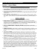
Series 403X Storefront Installation Instructions Section 1. General Notes HANDLING / STORING / PROTECTING ALUMINUM The following guidelines are recommended to ensure early acceptance of your products and workmanship. A. HANDLE CAREFULLY - Store with adequate separation between components so the material will not rub together. Store the material off the ground. Protect materials against weather elements and other construction trades. B.
Series 403X Storefront Installation Instructions Section 2.
Series 403X Storefront Installation Instructions Section 2. Parts Identification Horizontal Parts (cont.
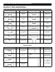
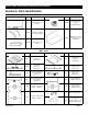
Series 403X Storefront Installation Instructions Section 2. Parts Identification Sill and End-Dam Parts Profile Part # Description 21T1 High Performance Sill Flashing HDW1 Water Deflector @ Intermediate Horizontal HCW6 Profile Part # Description WM01 Bond Breaker Tape 4” X .062” Used @ Sill Splices KO46 Sill Flashing End-Dam Package Use w/ 21T1 Sill Flashing Weep Baffle used @ Sill Misc.
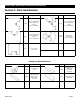
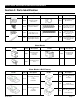
Series 403X Storefront Installation Instructions Section 2. Parts Identification Misc. Parts (cont.
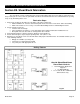
Series 403X Storefront Installation Instructions Section 3A. Screw Spline Fabrication The screw spline system is a fabrication and erection method that permits the preassembly of single units in the shop or at the job site. These units are then erected by mating the male mullion of one unit to its counterpart female mullion of the adjoining unit. Notes: 1. When an entrance is required, shear block joinery must be used to attach the side lite horizontals. 2.
Series 403X Storefront Installation Instructions Section 3A. Screw Spline Fabrication (cont.) Outside Glazed Bead-Up Screw Spline Verticals Left Hand Shown, Right Hand Opposite Use Drill Jig #DJ50 Use a .230” dia. No. 1 drill bit at darkened holes only. Fig. #2 Inside Glazed Screw Spline Verticals Left Hand Shown, Right Hand Opposite Use Drill Jig #DJ50 Use a .230” dia. No. 1 drill bit at darkened holes only. Fig.
Series 403X Storefront Installation Instructions Section 3B. Shear Block Fabrication The shear block system is a fabrication and erection method that permits the preassembly of single units in the shop or at the job site. These units are joined with shear blocks and then installed as an assembled unit in the opening on top of any sill flashing that is used. Fabrication Steps: 1. Measure the opening to determine the cut lengths of the frame components.
Series 403X Storefront Installation Instructions Section 3B. Shear Block Fabrication (cont.) Outside Glazed Bead-Up Shear Block Verticals Left Hand Shown, Right Hand Opposite Use Drill Jig #DJ46 Use a .180” dia. No. 15 drill bit at darkened holes only. Fig. #5 Inside Glazed Shear Block Verticals Left Hand Shown, Right Hand Opposite Use Drill Jig #DJ46 Use a .180” dia. No. 15 drill bit at darkened holes only. Fig.
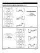
Series 403X Storefront Installation Instructions Section 3B. Shear Block Fabrication (cont.) DJ49 Shear Block Horizontals DJ49 21S5 Shown, also for open back and tubular intermediate horizontals. Use Drill Fixture #DJ49 placed at each end of horizontal as shown. Use a .230” dia. No. 1 drill bit for each hole. 21S5 Fig. #7 F724 21S5 21S2 Shear Block Horizontals DJ47 F722 F722 DJ47 F722 F722 (a) Use Drill Fixture #DJ47 placed at each end of horizontal as shown.
Series 403X Storefront Installation Instructions Section 3C. Corner Fabrication Notes: 1. 2. 3. 4. 5. 6. 90⁰ Corners are designed for use with the shear block or screw spline system. Because of possible screw spline and corner snap interference, the 3 way corners must be shear block system only. Do Not measure hole locations from locking corners. All 4 1/2” vertical corners can be mated together or with any other corner regardless of system considerations.
Series 403X Storefront Installation Instructions Section 3C. Corner Fabrication (cont.) Fixed, Inside, Outside, and 135⁰ Corners Shear block application only. Follow steps 1, 2, and 5 in Section 3B for cut lengths and hole preparations. #2G56 Inside Corner 2G57 Outside Corner #8558 ** Reverse Mullions For Inside Corners ** Fig. #11 Variable Degree Corners Screw spline construction ONLY.
Series 403X Storefront Installation Instructions Section 3D. Expansion Mullions Expansion mullions are required in elevations that are over 20’ - 25’ wide and can be used with both screw spline and shear block systems. Do Not use expansion mullions at entrance jambs. Locate the expansion mullion at the next vertical mullion over so that the distance between expansion mullions is never more than 25’-0”. Screw Spline System Fabrication Steps: 1.
Series 403X Storefront Installation Instructions Section 3E. Steel Reinforcing Fabrication Steps: Cut the steel reinforcing to mullion length minus 3” and set flush with the bottom of the vertical. Paint the cut ends to prevent rust. Insert the steel into the mullion, then drill through the deep pocket of the mullion and the steel reinforcing at 16” oncenter - maximum spacing. Tap the hole in the steel to accept proper machine screw for that mullion and steel reinforcing combination.
Series 403X Storefront Installation Instructions Section 3F. Unit Assembly - Screw Spline Assembly Steps: Butter the ends of all horizontals and fill vertical glazing vinyl pockets with butyl type sealant as represented by the shaded areas in Fig. #15. (Place sealant as shown unless ladder to be installed in opening immediately, then coat complete end of horizontal.) Wax type lubricant may be required at assembly fasteners. Screw complete system together as shown in Fig. #15.
Series 403X Storefront Installation Instructions Section 3F. Unit Assembly - Shear Block Assembly Steps: Butter the ends of all horizontals and fill vertical glazing vinyl pockets with butyl type sealant as represented by the shaded areas in Fig. #16. Wax type lubricant may be required at assembly fasteners and dead load pins. Attach all shear block to verticals with fasteners provided.
Series 403X Storefront Installation Instructions Section 4A. Door Frame Installation Notes: If NO door frame is required, proceed to Section 4B. If a door frame is required, the frame must be installed first. All subsequent ladders must be installed from the door frame out. Door frame jambs do not set on sill flashing. Door jambs must run through to the floor condition.
Series 403X Storefront Installation Instructions Section 4B. Sill Flashing Fabrication Fabrication Steps: 1. Cut Length - Measure the rough opening width. Subtract a 1/4” per sill flashing end for the thickness of the water dam and the fastener head height from the rough opening. With End Dams: CUT LENGTH = ROUGH OPENING - 1/4” x (# of ends with end dam) Without End Dams: CUT LENGTH = ROUGH OPENING 2. Weep Holes - Drill a min.
Series 403X Storefront Installation Instructions Section 4B. Sill Flashing Installation Installation Steps: 1. Chalk Line - Before installing the sill flashing, measure the distance from the exterior of the condition to the desired location of the exterior of the sill flashing. Do this at both ends of the opening. If the opening is too wide for just two marks, measure every 15 feet. Snap a chalk line between the marks to align sill flashing. 2.
Series 403X Storefront Installation Instructions Section 4B. Sill Flashing Installation (cont.) Splicing Steps: 1. Verify Sill Flashing - Check to see that sill flashing has been installed correctly. Sill flashing to be spliced every 20’ - 25’. Splice locations are to be located at least 6” from any vertical intermediate mullion. 2. Splice Gap - Make sure a 1/4” gap is left at every sill flashing splice location. 3. Splice Material - Use a silicone type sealant and a strip of WM01 bond breaker tape.
Series 403X Storefront Installation Instructions Section 4C. Installation Installation Steps: 1. Sealing the sill onto the Sill Flashing - Apply a silicone type sealant to the sill flashing as shown in Fig. #25(a) before installing the first ladder of frame. Make sure enough sealant is applied to seal the areas shown. After all frame ladders are installed clean all excess sealant from any exposed areas. 2.
Series 403X Storefront Installation Instructions Section 4C. Installation 5. Installing additional Frame Ladders - Make sure that the head and jamb have been shimmed and anchors have been installed on the previous frame ladder. Apply sealant to the sill flashing as sown in Fig. #25(a) on page 23. Place the additional ladder onto the sill flashing at approximately 1/4” from previously installed frame ladder and follow steps 2 and 3 from page 23.
Series 403X Storefront Installation Instructions Section 5A&B. Water Deflector, Glass Pocket, & Glass Sizes 1. Water Deflector - Install the HWD1 at the ends of the intermediate horizontals only. It is not required at heads or sills. Use a silicone type sealant and place some on the horizontal to adhere the HWD1 onto the intermediate horizontals.
Series 403X Storefront Installation Instructions Section 5C. Glazing Glass Installation Steps 1. Glass Blocks - Place glass blocks at the standard 1/4 point locations. It may be necessary to place a small amount of sealant on the bottom of the glass blocks to ensure they remain in their intended position. Refer to approved shop drawings or consult project design professional to verify glass block locations. 2.
Series 403X Storefront Installation Instructions Section 5C. Glazing Glass Installation Steps (cont.) 3. Glass Installation - Make sure glass blocks are still in place. After getting glass based upon glass size formulas on page 25 follow these steps: A. Position the glass on the appropriate side of the framing without the removable glass stop installed. Shift the glass into the deep pocket to begin glass installation. B. Swing the opposite glass edge around to align with the glazing pocket. C.
Series 403X Storefront Installation Instructions Section 5C. Glazing Glass Installation Steps (cont.) 5. Anti-Walk Block Installation - Make sure the glass unit is pushed as far into shallow pocket as possible. Stretch the anti-walk block out as shown in Fig. #35. Slide the stretched out block between the glass unit and glazing gasket track and push it fully into the deep glass pocket at the midpoint of the glass unit. Use Anti-Walk Blocks At Deep Pockets Only 6.
Series 403X Storefront Installation Instructions Section 5D. Window Adaptors and Glazing Adaptor Equal Leg Shadowline Adaptor For 1” glazing pockets only. Horizontal Cut Length = D.L.O. - 1/16” (Horizontal pieces run thru) Vertical Cut Length = D.L.O. - 11/32” 1/8” x 5/8” notch at back of vertical pieces to clear horizontal leg. (See Fig. #36) Seal Joint Completely For equal leg Shadowline windows: Window Dim. = D.L.O. - 9/16” W104 SFQ2 Fig.