SERIES 433 Triple Set Installation Instructions Part NO.
Series 433 Triple Set Installation Instructions TABLE OF CONTENTS SECTION PAGE I. General Notes……………………………………..…………………………………………………………………..…...3 II. Parts Identification Charts………………………………………………………………………………………..……..4 III. Fabrication A. Drilling Template (Offset Screw Spline Verticals)………………………………………..………..….…12 B. Drilling Template (Offset Shear Block Verticals)….………………………………………….……..……15 C. Drilling Template (Center-Set Screw Spline Verticals)………………………………………………....18 D.
Series 433 Triple Set Installation Instructions SECTION I: General Notes The “433 TRIPLE SET” is a framing system that has many advantages over other framing systems. It can be used as a single-span storefront window wall, a punched opening system, or as a ribbon window system. The main advantage is the ability to set the glass plane in three different positions within the same elevation. The 433 Triple Set system contains primarily stock length systems with in-the-field fabrication.
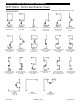
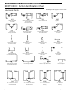
Series 433 Triple Set Installation Instructions SECTION II: Parts Identification Chart Drawings on this page are not to scale.
Series 433 Triple Set Installation Instructions SECTION II: Parts Identification Chart Vertical Parts cont.: Drawings on this page are not to scale.
Series 433 Triple Set Installation Instructions SECTION II: Parts Identification Chart Drawings on this page are not to scale.
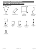
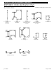
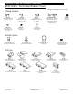
Series 433 Triple Set Installation Instructions SECTION II: Parts Identification Chart Horizontal Parts: 16B9 4 ½” Offset Head & Sill Face Cover Use w/4G31 4G29 4 ½” Offset Glazed Head 3S67 Adjustable Sidelite Sill June 2012 Drawings on this page are not to scale.
Series 433 Triple Set Installation Instructions SECTION II: Parts Identification Chart Drawings on this page are not to scale.
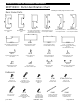
Series 433 Triple Set Installation Instructions SECTION II: Parts Identification Chart Shear Blocks: Drawings on this page are not to scale. K919 K918 LH or RH C.O.C. Header Shear Block Pkg. for Pivots, Butts or Cont. Hinge Use w/ 9227, 9234 or 2556 K925 K926 Shear Block Pkg. for Offset Horizontal/Head Use w/8363,8366,8385 or 8393 Shear Block Pkg. for Center-Set Sill Use w/8375 KN53 K924 Shear Block Pkg. for CenterSet Horizontal/Head Use w/8372 K927 Shear Block Pkg.
Series 433 Triple Set Installation Instructions SECTION II: Parts Identification Chart Drawings on this page are not to scale.
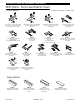
Series 433 Triple Set Installation Instructions SECTION II: Parts Identification Chart Drawings on this page are not to scale. Misc. Parts: HN44 Head & Sill Foam Splice Joint LB90 Vinyl Center-Set Pocket Filler @ Perimeter Condition Use W/8355, 8356, 8361 WM01 Bond Breaker Tape 4” X .
Series 433 Triple Set Installation Instructions SECTION III: Fabrication A. Drilling Template Offset Screw Spline Verticals (Offset Mullion) Left Hand Mullion Shown, Right Hand Opposite Use the exterior edge of the vertical to align Drill Jig DJ15. Use .221 dia. (#2) drill at darkened areas only. These preps work for both inside and outside glazed versions. Outside Set Mullion Inside Set Mullion OFF 433SET S.S. DJ15 CENTER SET OFF SET OFF SET CENTER SET 433 S.S. OFF SET DJ15 CENTER SET OFF 433SET S.S.
Series 433 Triple Set Installation Instructions SECTION III: Fabrication A. Drilling Template Offset Screw Spline Verticals (Offset Mullion Filler) Left Hand Mullion Filler Shown, Right Hand Opposite Use the exterior edge of the vertical to align Drill Jig DJ15. Use .221 dia. (#2) drill at darkened areas only. These preps work for both inside and outside glazed versions. PART NO. Y017 OFF SET OFF SET OFF SET CENTER SET CENTER SET CENTER SET DJ15 OFF SET OFF SET OFF SET 433 S.S. DJ15 DJ15 433 S.S.
Series 433 Triple Set Installation Instructions SECTION III: Fabrication A. Drilling Template Offset Screw Spline Verticals (Offset Mullion) with 4 ½” Horizontals Left Hand Mullion Shown, Right Hand Opposite OFF SET OFF SET OFF SET OFF SET OFF SET CENTER SET CENTER SET OFF SET OFF SET CENTER SET CENTER SET OFF SET OFF SET OFF SET DJxx 433 S.S. CENTER SET OFF SET 433 S.S. DJxx OFF SET June 2012 CENTER SET Use the exterior edge of the vertical to align Drill Jig DJ25. Use .221 dia.
Series 433 Triple Set Installation Instructions SECTION III: Fabrication B. Drilling Template Offset Shear Block Verticals (Offset Mullion) Left Hand Mullion Shown, Right Hand Opposite Use the exterior edge of the vertical to align Drill Jig DJ14. Use .182 dia. (#14) drill at darkened areas only. These preps work for both inside and outside glazed versions. Outside Set Mullion Inside Set Mullion 1 3/4" 1 3/4" 11/16" 5/8" 5/8" CENTER SET 433 S.B. DJ14 433 S.B.
Series 433 Triple Set Installation Instructions SECTION III: Fabrication B. Drilling Template Offset Shear Block Verticals (Offset Mullion Filler) Left Hand Mullion Shown, Right Hand Opposite Use the exterior edge of the vertical to align Drill Jig DJ14. Use .182 dia. (#14) drill at darkened areas only. These preps work for both inside and outside glazed versions. Outside Set Mullion Filler Inside Set Mullion Filler CENTER SET 433 S.B. DJ14 433 S.B. DJ14 OFF SET CENTER SET 433 S.B. DJ14 433 S.B.
Series 433 Triple Set Installation Instructions SECTION III: Fabrication B. Drilling Template Offset Shear Block Verticals (Offset Mullion) with 4 ½” Horizontals Left Hand Mullion Shown, Right Hand Opposite Use the exterior edge of the vertical to align Drill Jig DJ24. Use .182 dia. (#14) drill at darkened areas only. These preps work for both inside and outside glazed versions. Outside Set Mullion June 2012 Inside Set Mullion PART NO.
Series 433 Triple Set Installation Instructions SECTION III: Fabrication C. Drilling Template Center-Set Screw Spline Verticals (Center-Set Mullion) Left Hand Mullion Shown, Right Hand Opposite Use the exterior edge of the vertical to align Drill Jig DJ15. Use .221 dia. (#2) drill at darkened areas only. These preps work for both inside and outside glazed versions.
Series 433 Triple Set Installation Instructions SECTION III: Fabrication C. Drilling Template Center-Set Screw Spline Verticals (Center-Set Mullion) with 4 ½” Horizontals Left Hand Mullion Shown, Right Hand Opposite Use the exterior edge of the vertical to align Drill Jig DJ25. Use .221 dia. (#2) drill at darkened areas only. These preps work for both inside and outside glazed versions.
Series 433 Triple Set Installation Instructions SECTION III: Fabrication D. Drilling Template Center-Set Shear Block Verticals (Center-Set Mullion) Left Hand Mullion Shown, Right Hand Opposite Use the exterior edge of the vertical to align Drill Jig DJ14. Use .182 dia. (#14) drill at darkened areas only. These preps work for both inside and outside glazed versions. Center-Set Mullion (Reverse Drill Jig for the opposite side) CENTER SET OFF SET OFF SET 433 S.B. DJ14 Outside Glazed 433 S.B.
Series 433 Triple Set Installation Instructions SECTION III: Fabrication D. Drilling Template Center-Set Shear Block Verticals (Center-Set Mullion) with 4 ½” Horizontals Left Hand Mullion Shown, Right Hand Opposite Use the exterior edge of the vertical to align Drill Jig DJ23. Use .182 dia. (#14) drill at darkened areas only. These preps work for both inside and outside glazed versions. Center-Set Mullion (Reverse Drill Jig for the opposite side) Inside Glazed June 2012 PART NO.
Series 433 Triple Set Installation Instructions SECTION III: Fabrication D. Drilling Template Center-Set Shear Block Verticals & Horizontals (2-Piece Slope or Arch Top) Left Hand Mullion Shown, Right Hand Opposite Vertical Fabrication: Outside Glazed Shown Inside Opposite Use .147 dia. (#26) drill at darkened areas only. These preps work for both inside and outside glazed versions. Horizontal Fabrication 3/16” Dia. Thru Hole (1) Wall.
Series 433 Triple Set Installation Instructions SECTION III: Fabrication E. Drilling Template Offset @ 90° Corner Horizontal/Head/Sill Use .246 Diameter (#D) Drill Bit 8475 8384 TOP OF SILL MEASURE CUT LENGTH FROM THIS FLAT EDGE CENTERLINE OF MULLION 8475 TOP OF HEAD TOP OF HORIZ. 8393 8385 MEASURE CUT LENGTH FROM THIS FLAT EDGE CENTERLINE OF MULLION June 2012 PART NO.
Series 433 Triple Set Installation Instructions SECTION III: Fabrication E. Drilling Template Offset @ 90° Corner Horizontal/Head/Sill 4 ½” Horizontals Use .246 Diameter (#D) Drill Bit June 2012 PART NO.
Series 433 Triple Set Installation Instructions SECTION III: Fabrication F. Drilling Template for Offset and Center-Set Shear Block at Sills Fixture DJ13 should be placed at the end of the sills as shown. These preps work on all offset and center-set sills. Use .246 Diameter (#D) Drill Bit CENTER THE .246 DIA. HOLE AT MIDPOINT OF FLAT 45° 1" 1" DJ13 8362 FU20 (Typ. at each end) 1" 1" 8372 8372 FU19 FU19 DJ13 DJ13 FU19 FU19 Drill one side and flip the fixture to drill the opposite side. (Typ.
Series 433 Triple Set Installation Instructions SECTION III: Fabrication F. Drilling Template for Offset and Center-Set Shear Block at 4 ½” Sills Fixture DJ13 should be placed at the end of the sills as shown. These preps work on all offset and center-set sills. Use .246 Diameter (#D) Drill Bit CENTER THE .246 DIA. HOLE AT MIDPOINT OF FLAT 45° 1" 1" 4G33 DJ13 FU20 FU20 (Typ. at each end) 1" 1" 3G48 3G48 FU19 FU19 DJ13 DJ13 FU19 June 2012 PART NO.
Series 433 Triple Set Installation Instructions SECTION III: Fabrication G. Drilling Template Offset and Center-Set Shear Block at Horizontals Fixture DJ12 is self-aligning and should be placed at the end of the horizontal as shown. These preps work on all offset head and intermediate horizontals. Use .246 Diameter (#D) Drill Bit Fixture DJ13 should be placed at the end of the horizontal as shown. These preps work on all center-set head and intermediate horizontals. Use .
Series 433 Triple Set Installation Instructions SECTION III: Fabrication G. Drilling Template Offset and Center-Set Shear Block at 4 ½” Horiz. Fixture DJ26 is self-aligning and should be placed at the end of the horizontal as shown. These preps work on all offset head and intermediate horizontals. Use .246 Diameter (#D) Drill Bit Fixture DJ26 should be placed at the end of the horizontal as shown. These preps work on all center-set head and intermediate horizontals. Use .
Series 433 Triple Set Installation Instructions SECTION III: Fabrication H. Drilling Template Offset Glazed Head & Sill Through Head and Sill through Butt Glazed Jamb and Vertical Use the exterior edge of the jamb or vertical to align drill jig DJ15. Use .221 diameter (#2) drill bit at darkened areas only. June 2012 PART NO.
Series 433 Triple Set Installation Instructions SECTION III: Fabrication H. Drilling Template Offset Screw Spline SSG Verticals for Intermediate Horizontal with Head & Sill Through Use the exterior edge of the vertical to align Drill Jig DJ15 for 2” mullions and DJ25 for 4 ½” mullions. Use .221 dia. (#2) drill at darkened areas only. 433 S.S. DJ15 OFF SET OFF SET CENTER SET OFF SET CENTER SET OFF SET 8387 8387 8388 8388 June 2012 PART NO.
Series 433 Triple Set Installation Instructions SECTION III: Fabrication H. Drilling Template Offset Shear Block SSG Verticals for Intermediate Horizontal with Head & Sill Through Use the exterior edge of the vertical to align Drill Jig DJ14 for 2” mullions and DJ24 for 4 ½” mullions. Use .201 dia. (#7) drill at darkened areas only. CENTER SET 433 S.B. DJ14 OFF SET CENTER SET 8389 8389 June 2012 PART NO.
Series 433 Triple Set Installation Instructions SECTION IV: Unit Assembly A. Screw Spline (Offset and Center-Set) Offset Glazed Assembly Outside Set, Inside glazed shown, Outside Set, Outside Glazed Similar Note: Wax Type Lubricate may be required @ Assembly Fasteners 4 ½” Head, Horizontal & Sill Similar Note: Clean off all excess sealant after assembly. June 2012 PART NO.
Series 433 Triple Set Installation Instructions SECTION IV: Unit Assembly A. Screw Spline (Offset and Center-Set) Offset Glazed Assembly Inside Set, Outside glazed shown, Inside Set, Inside Glazed Similar Note: Wax Type Lubricate may be required @ Assembly Fasteners 4 ½” Head, Horizontal & Sill Similar Butter the ends fo all horizontals with sea Note: Clean off all excess sealant after assembly. June 2012 PART NO.
Series 433 Triple Set Installation Instructions June 2012 PART NO.
Series 433 Triple Set Installation Instructions SECTION IV: Unit Assembly A. Screw Spline (Offset and Center-Set) Center Glazed Assembly Inside Glazed 8361 SHOWN (8358, 8359 SIM.) Note: Wax Type Lubricate may be required @ Assembly Fasteners 4 ½” Head, Horizontal & Sill Similar BUTTER THE ENDS OF ALL HORIZONTALS WITH BUTYL TYPE SEALANT AS SHOWN BY THE SHADED AREAS PRIOR TO ASSEMBLY OF THE UNITS. STC8 STC8 STC8 EXTERIOR FACE 8360 Note: Clean off all excess sealant after assembly.
Series 433 Triple Set Installation Instructions SECTION IV: Unit Assembly A. Screw Spline (Offset and Center-Set) Offset Structural Glazed Assembly 4 ½” Head, Horizontal & Sill Similar Note: Wax Type Lubricate may be required @ Assembly Fasteners STC8 8355 Details shown without removable face for clarity. 8393 8387 STC8 STC8 8385 8388 8393 8385 8384 BUTTER THE ENDS OF ALL HORIZONTALS WITH BUTYL TYPE SEALANT AS SHOWN BY THE SHADED AREAS PRIOR TO ASSEMBLY OF THE UNITS.
Series 433 Triple Set Installation Instructions SECTION IV: Unit Assembly A. Screw Spline (Offset and Center-Set) Offset Glazed Assembly With Expansion Mullion Outside Set, Inside Glazed Shown, Outside Set, Outside Glazed Similar 4 ½” Head, Horizontal, & Sill Similar Note: Wax Type Lubricate may be required @ Assembly Fasteners. Note: Clean off all excess sealant after assembly.
Series 433 Triple Set Installation Instructions SECTION IV: Unit Assembly A. Screw Spline (Offset and Center-Set) Center Glazed Assembly With Expansion Mullion Inside Glazed 4 ½” Head, Horizontal, & Sill Similar Note: Wax Type Lubricant may be required @ Assembly Fasteners. EXTERIOR FACE Note: Clean off all excess sealant after assembly. BUTTER THE ENDS OF ALL HORIZONTALS WITH BUTYL TYPE SEALANT AS SHOWN BY THE SHADED AREAS PRIOR TO ASSEMBLY OF THE UNITS.
Series 433 Triple Set Installation Instructions SECTION IV: Unit Assembly A. Screw Spline (Offset and Center-Set) Dead Load Pin Installation Outside Set Shown Inside Set Similar Use FW95 3” Dead Load Support Pin when there is a Horizontal member on both sides of the Transom Jamb or Vertical. Use FW96 2” Dead Load Support Pin when there is a Horizontal member on one side of the Vertical or for Door Jambs with side lites. 4374 8353 8354 8356 8355 8374 DIES SIMILAR TO ONE’S SHOWN. June 2012 PART NO.
Series 433 Triple Set Installation Instructions SECTION IV: Unit Assembly B. Shear Block (Offset and Center-Set) Offset Glazed Assembly 4 ½” Head, Horizontal & Sill Similar Inside Set, Inside Glazed shown, Other Glazing Variations Similar K925 KN91 (4 ½”) Shear block packages come with all required fasteners. Note: Wax Type Lubricate may be required @ Assembly Fasteners BUTTER THE ENDS OF ALL HORIZONTALS WITH BUTYL TYPE SEALANT AS SHOWN BY THE SHADED AREAS PRIOR TO ASSEMBLY OF THE UNITS.
Series 433 Triple Set Installation Instructions SECTION IV: Unit Assembly B. Shear Block (Offset and Center-Set) Center-Set Glazed Assembly 4 ½” Head, Horizontal & Sill Similar Inside Glazed shown, Outside Glazed similar Note: Wax Type Lubricate may be required @ Assembly Fasteners K924 KN69 (4 ½”) Shear block packages come with all required fasteners. 8372 BUTTER THE ENDS OF ALL HORIZONTALS WITH BUTYL TYPE SEALANT AS SHOWN BY THE SHADED AREAS PRIOR TO ASSEMBLY OF THE UNITS.
Series 433 Triple Set Installation Instructions SECTION IV: Unit Assembly B. Shear Block (Offset and Center-Set) Dead Load Pin Installation Outside Set Shown Inside Set Similar Use FW95 3” Dead Load Support Pin when there is a Horizontal member on both sides of the Transom Jamb or Vertical. Use FW96 2” Dead Load Support Pin when there is a Horizontal member on one side of the Vertical or for Door Jambs with side lites. 8374 8349 OTHER DIES SIMILAR TO ONE’S SHOWN. June 2012 PART NO.
Series 433 Triple Set Installation Instructions SECTION IV: Unit Assembly C. Head & Sill Through (Offset) Offset Structural Glazed Assembly STB5 Horizontal shown without removable face for clarity Note: Wax Type Lubricate may be required @ Assembly Fasteners 8363 BUTTER THE ENDS OF ALL HORIZONTALS WITH BUTYL TYPE SEALANT AS SHOWN BY THE SHADED AREAS PRIOR TO ASSEMBLY OF THE UNITS. Shear block packages come with all required fasteners.
Series 433 Triple Set Installation Instructions SECTION IV: Unit Assembly D. Screw Spline 90 Corner (Offset) Offset Glazed Assembly with 90 Mullion Corner Mullion can be used at horizontal with removable face only. See page 31 for sealant notes and locations. 4 ½” Head, Horizontal & Sill Similar Note: Wax Type Lubricate may be required @ Assembly Fasteners June 2012 PART NO.
Series 433 Triple Set Installation Instructions SECTION IV: Unit Assembly E. Rolled Arch Top & Sloped Top (Center Set) Center Glazed Assembly for Slope or Arch Top Note: Wax Type Lubricate may be required @ Assembly Fasteners Inside or Outside Glazed BUTTER THE ENDS OF ALL HORIZONTALS WITH BUTYL TYPE SEALANT AS SHOWN BY THE SHADED AREAS PRIOR TO ASSEMBLY OF THE UNITS. ROLLED 16C8 Shear block packages come with all required fasteners.
Series 433 Triple Set Installation Instructions SECTION IV: Unit Assembly F. Adjustable Height Side Lite (Offset) D.L.O. BREAKMETAL WIDTH = D.L.O. SEALANT STT6 16E1 SEALANT HN64 16D9 W104 SPZ1 BREAKMETAL HEIGHT = D.L.O. + .656 STT6 D.L.O. SIDE LITE HEIGHT = 4 1/2" MIN. TO 48" MAX. 8365 W161 .375 2S44 SUBSILL June 2012 3S67 PART NO.
Series 433 Triple Set Installation Instructions SECTION IV: Unit Assembly F. Adjustable Height Side Lite (Offset) Part Fabrication CUT LENGTH = D.L.O. - .75 12" O.C. MAX 1.500 .375 12" O.C. MAX 1.500 .375 .156 .156 .500 16E1 Ø.177 THRU HOLE FOR #8-18 FASTENERS (2) AT EACH END, ADD (1) IN THE MID SPAN IF CUT LENGTH EXCEEDS 19" AND UP TO 35" OR 12" O.C. FOR CUT LENGTHS OVER 35" .563 .375 .563 .375 CUT LENGTH = D.L.O. .500 .500 .423 Ø.177 THRU HOLE (4) OF HORIZONTAL 2.786 16D9 1.000 .234 .
Series 433 Triple Set Installation Instructions SECTION IV: Unit Assembly F. Adjustable Height Side Lite (Offset) Assembly ATTACH THE VERTICAL MEMBERS TO THE SILL AS SHOWN. OPTIONAL DEAD LOAD SUPPORT TUBE TO BE USED AS NEEDED. RUN A CONTINUOUS BEAD OF SEALANT UP THE INTERIOR GASKET RACEWAY FOR THE FULL LENGTH OF THE SIDE LITE VERTICAL. BUTTER THE ENDS OF ALL HORIZONTALS WITH BUTYL TYPE SEALANT PRIOR TO ASSEMBLY OF THE UNITS. 9838 DEAD LOAD SUPPORT TUBE PLACE ASSEMBLY IN THE FRAME D.L.O.
Series 433 Triple Set Installation Instructions SECTION V: Door Frame Installation Step 1) General Notes If a door opening is required, the doorframe must be installed first. The subsill must be installed into the opening from the door framing, ensuring that the appropriate clearance is available for the doorframe. All subsequent ladders must be installed from the doorjamb out. INSTALL 1ST 2" 2" Fig. 1 SUBFRAME CLEARANCE HOLE = [DOOR OPENING WIDTH + 4"] Note: Door jambs do not set on the subsill.
Series 433 Triple Set Installation Instructions SECTION V: Door Frame Installation Step 3) Subsill Installation at Door Opening Before installing the subsill to the door frame, seal the end of the subsill with a silicone type sealant. Install the subsill and tool all excess sealant into the joint where the subsill and door jamb meet. If required, add more sealant to create a smooth watertight seal.
Series 433 Triple Set Installation Instructions SECTION VI: Subsill Fabrication and Installation (Includes Offset and Center-Set Glazing) Step 1) Cut Length Measure the opening to determine the cut length of the subsill. Subtract ¼” for the width of the end dam and fastener head from the rough opening for each end. Cut the subsill to the determined length. If end dams are not required, cut the subsill to the rough opening width. CUT LENGTH = R.O.
Series 433 Triple Set Installation Instructions SECTION VI: Subsill Fabrication and Installation (Includes Offset and Center-Set Glazing) Step 3) Weep Fabrication Drill 5/16” weep holes in the subsill 6” from jambs and no more than 42” apart. SUBSILL 2S44 6" 42" MAXIMUM O.C. SEALANT 6" [Fig. 7] SUBSILL 4471 Step 4) Weep Baffle Installation Weep baffles are cut from (1) HCW6, halved. This provides (2) weep baffles per HCW6. See Fig. 8 below.
Series 433 Triple Set Installation Instructions SECTION VI: Subsill Fabrication and Installation (Includes Offset and Center-Set Glazing) Step 5) Chalk Line for Subsill Before installing the subsill, measure the distance from the exterior of the condition to the desired location at the EXTERIOR of the subsill. (The exterior of the subsill will be flush with the rest of the system.) Do this at both ends of the condition. Snap a chalk line between the two marks to align the subsill.
Series 433 Triple Set Installation Instructions SECTION VI: Subsill Fabrication and Installation (Includes Offset and Center-Set Glazing) Step 7) Subsill Anchor Installation At a minimum, anchor at 6" from jambs and corners and 16" O.C. Staggering locations from one side of thermal area to the other for 2S44 only. These recommendations are for general erection procedures only. For actual job conditions, see the details on the shop drawings.
Series 433 Triple Set Installation Instructions SECTION VI: Subsill Fabrication and Installation (Includes Offset and Center-Set Glazing) Do not use 4471 Subsill with heavy duty anchors. Step 8) Heavy-Duty Anchor Installation OUTSIDE SET GLASS Install required vertical mullion anchors as shown in Figures 14 through 18. Anchors should be installed on the vertical mullions and anchored thru the subsill after the frame unit is installed in the opening. HD anchors will not work with 8349 or 8357 mullions.
Series 433 Triple Set Installation Instructions SECTION VI: Subsill Fabrication and Installation (Includes Offset and Center-Set Glazing) Step 9) Subsill Anchor Seal The subsill anchors must be sealed with a silicone type sealant. To ensure a good seal, tool the sealant onto the fastener and surrounding metal. If HD anchors are used, ensure that the anchor angle and fasteners are sealed also. This procedure should be followed immediately after anchor installation so it is not forgotten. [FIG.
Series 433 Triple Set Installation Instructions SECTION VI: Subsill Fabrication and Installation (Includes Offset and Center-Set Glazing) Step 11) Subsill Splicing Verify that the subsill has been installed according to the instructions on pages 45 through 52. Splice areas are to be centered at a vertical mullion only. Maximum subsill length between splices is 20’ to 25’. If a splice is required, leave a 1/4" gap between the subsill ends at the splice area. Install and anchor the next run of subsill.
Series 433 Triple Set Installation Instructions SECTION VI: Subsill Fabrication and Installation (Includes Offset and Center-Set Glazing) Step 12) Subsill Corner Miter and Splicing When mitering the subsill for corner applications, cut the subsill material at the appropriate angle required to form the correct corner. Install the subsill by following the previous subsill installation instructions.
Series 433 Triple Set Installation Instructions SECTION VII: Corners (Includes Offset and Center-Set Glazing) Corner Identification and Assembly Proper identification of the required corner members is necessary to ensure a timely installation process. See details of each corner variation on pages 55 through 57 in Figures 23 through 33.
Series 433 Triple Set Installation Instructions SECTION VII: Corners (Includes Offset and Center-Set Glazing) [FIG. 25] [FIG. 26] NOTE:NOTE: Figure Figure 26 shows Inside 26 can be and Outside set verticals. You can by create a multi-plane accommodated using vertical mullions from Figures 23, and 25 configuration by using any of the 24, vertical in any combination. mullions shown in figures 23, 24 and 25. [FIG. 28] [FIG. 27] June 2012 PART NO.
Series 433 Triple Set Installation Instructions SECTION VII: Corners (Includes Offset and Center-Set Glazing) [FIG. 29] NOTE: Figure 30 30 canshows be NOTE: Figure Inside accommodated by using vertical and Outside set verticals. mullions from Figures 27, 28, You and 29 in any can combination. create a multi-plane configuration by using any of the vertical mullions shown in figures 27, 28 and 29. [FIG. 30] [FIG. 31] [FIG. 32] [FIG.
Series 433 Triple Set Installation Instructions SECTION VIII: Installation (Includes Offset and Center-Set Glazing) Step 1) Sealing the Sill onto the Subsill Apply a silicone type sealant to the subsill in the location shown in Figure 34 before installing the first ladder. Make sure that enough sealant is applied to seal the areas shown in Figure 35. After installing the ladder and anchoring it, clean off all excess sealant from exposed areas.
Series 433 Triple Set Installation Instructions SECTION VIII: Installation (Includes Offset and Center-Set Glazing) Step 2) Installing Jamb Side Ladder Place the ladder on the subsill at an approximate 30° angle. While applying pressure upward, rotate the ladder into the condition. See Figure 35 on page 58 for sill placement into the subsill. When rotated correctly, the exterior face of the sill should be flush with the exterior face of the subsill. CONDITION LADDER [FIG.
Series 433 Triple Set Installation Instructions SECTION VIII: Installation (Includes Offset and Center-Set Glazing) Step 3) Anchoring the Head For D.L.O.s 36" and narrower, the anchors must be spaced 6" from the jamb or vertical members. For D.L.O.s 36" and wider, the outside anchors must be spaced 6" from the jamb with the center anchor centered on the D.L.O. See Figure 38 below. These recommendations are for general erection procedures only.
Series 433 Triple Set Installation Instructions SECTION VIII: Installation (Includes Offset and Center-Set Glazing) Step 4) Anchoring the Jambs Anchors must be spaced 6" from the sill or head, and 24" O.C. ± 4", so they do not interfere with the horizontal members. See Figure 42. Regardless of glass pocket configuration, the anchors should be placed so they do not fasten through the thermal area. See Figures 43 through 46. These recommendations are for general erection procedures only.
Series 433 Triple Set Installation Instructions SECTION VIII: Installation (Includes Offset and Center-Set Glazing) Step 5) Sealing Vertical Mullions Prior to installing an intermediate vertical mullion or perimeter jamb, apply silicone type sealant to the vertical mullion in the location shown in Figure 47 below at the Interior joints only. Apply sealant where indicated 6-8 inches up from the bottom of the vertical joints.
Series 433 Triple Set Installation Instructions SECTION VIII: Installation (Includes Offset and Center-Set Glazing) SEAL SEAL 8354 8359 8354 8356 [FIG. 51] [FIG. 52] SEAL 8356 SHOWN IN CORNER MULLIONS, OTHERS SIMILAR. SEAL 8356 8380 [FIG. 54] 8356 8356 8356 8381 [FIG. 53] Seal Vertical 6”-8” from the bottom up. June 2012 PART NO.
Series 433 Triple Set Installation Instructions SECTION VIII: Installation (Includes Offset and Center-Set Glazing) Step 6) Installing the Second Ladder Make sure that the anchors are installed into the head and jamb of the first ladder. Apply the sealant as specified in Figures 47 through 54 on pages 66 and 67. Apply sealant to the subsill as shown on page 40. Place the second ladder on the subsill at an approximate 30° angle.
Series 433 Triple Set Installation Instructions SECTION VIII: Installation (Includes Offset and Center-Set Glazing) Step 7) Snapping Vertical Mullions Together To snap vertical mullions together, line up the mullion halves once the 1/4" gap is achieved between the mullion halves. See Figure 56 on page 64. Place one clamp at the bottom of the mullions using wood blocks to protect the extrusions. Tighten the clamp until the mullion halves begin to snap together.
Series 433 Triple Set Installation Instructions SECTION VIII: Installation (Includes Offset and Center-Set Glazing) Step 8) Snapping the Expansion Mullion (Offset Mullion) To snap the expansion mullion together, line up the mullion halves and gaskets. See Figure 60. Place one clamp at the bottom of the expansion mullion using wood blocks to protect the extrusions. Tighten the C-clamp until the expansion mullion halves begin to snap together.
Series 433 Triple Set Installation Instructions SECTION VIII: Installation (Includes Offset and Center-Set Glazing) Step 9) Snapping the Expansion Mullion (Center-Set Mullion) To snap the expansion mullion together, line up the mullion halves and gaskets. See Figure 62. Place one clamp at the bottom of the expansion mullion using wood blocks to protect the extrusions. Tighten the C-clamp until the expansion mullion halves begin to snap together.
Series 433 Triple Set Installation Instructions SECTION VIII: Installation (Includes Offset and Center-Set Glazing) Step 10) Anchoring the Second Ladder After the mullion halves are snapped correctly, ensure that the mullions are plumb and true and anchor the head as shown in Figure 38 on page 64. If this is the last ladder in a run, ensure that the mullion halves are snapped correctly and install the required shims between the jamb and condition. Install the head and jamb anchors.
Series 433 Triple Set Installation Instructions SECTION IX: Glazing (Includes Offset and Center-Set Glazing) IDENTIFICATION OF GLASS POCKETS AND SETTING BLOCKS INSIDE GLAZED HORIZONTALS [FIG. 69] HN92 INSIDE GLAZED SILLS [FIG. 72] HN32 8363 8362 8365 [FIG. 70] HN92 [FIG. 73] 8366 8364 [FIG. 71] HN32 8362 8367 [FIG. 74] HN92 HN32 8375 8372 8368 4 ½” SILLS & HORIZONTALS SIMILAR Customer / Installer Note: EFCO setting blocks are typically 4" in length with different depths.
Series 433 Triple Set Installation Instructions SECTION IX: Glazing (Includes Offset and Center-Set Glazing) IDENTIFICATION OF GLASS POCKETS AND SETTING BLOCKS OUTSIDE GLAZED HORIZONTALS OUTSIDE GLAZED SILLS HN92 [FIG. 75] HN32 [FIG. 79] 8363 8362 8365 [FIG. 76] HN92 [FIG. 80] HN32 8366 8367 8362 8364 [FIG. 77] HN92 HN32 [FIG. 81] 8375 8372 8368 [FIG. 78] HN92 HN32 8385 [FIG.
Series 433 Triple Set Installation Instructions SECTION IX: Glazing (Includes Offset and Center-Set Glazing) Step 1) Identification of Glass Pockets INSIDE AND OUTSIDE GLAZED VERTICALS Ensure that each vertical DLO has at least one DEEP glass pocket on either side. It is necessary for the glazing installation that a deep pocket be used to load the glazing units. These details are shown with the deep glazing pockets shown right justified for viewing clarity. [FIG. 83] [FIG. 84] [FIG. 85] DEEP [FIG.
Series 433 Triple Set Installation Instructions SECTION IX: Glazing (Includes Offset and Center-Set Glazing) Step 2) Glass Size Formulas For captured glazing variations, the glass size formula is DLO + 7/8". For structural glaze systems the glass size formula is DLO + 1 1/2”. The glass size formula from captured mullion to SSG mullion is DLO + 1 3/16". From SSG mullion to SSG mullion the glass size formula is DLO + 1 1/2". Captured mullions have a glass bite of 7/16".
Series 433 Triple Set Installation Instructions SECTION IX: Glazing (Includes Offset and Center-Set Glazing) [FIG. 96] Step 3) Installing the Water Deflector This end extends into the vertical glazing pocket and over the lower glass unit's corner. HWD1 - WATER DEFLECTOR TYP. VERTICAL The HWD1 water deflector is designed to be universal. It may need to be modified to fit certain glazing pockets. Install the HWD1 at the ends of the intermediate horizontals only. It is not required at heads or sills.
Series 433 Triple Set Installation Instructions SECTION IX: Glazing (Includes Offset and Center-Set Glazing) Step 4) Installing Glass Blocks Glass blocks for the 433 system are designed to be used at 1/4 points and 1/8 points for special dead load applications. For intermediate horizontals, use glass block HN92. For sills, use glass block HN32. It may be necessary to use a small amount of sealant on the bottom of the glass blocks to ensure they remain in the intended position.
Series 433 Triple Set Installation Instructions SECTION IX: Glazing (Includes Offset and Center-Set Glazing) Step 5) Installation of Glazing Gasket For inside glazed applications, install the exterior gasket prior to glass installation. For outside glazed applications, install the interior gasket prior to glass installation. SIZE THE GASKET LENGTH BY USING THE FOLLOWING FORMULA. D.L.O. DIM X 1.005 (D.L.O. DIM. + 1/2%) NOTE: To install glazing gasket, start by pushing the gasket in place at the ends.
Series 433 Triple Set Installation Instructions SECTION IX: Glazing (Includes Offset and Center-Set Glazing) Step 6) Glass Installation A) Make sure the glazing blocks are still in place in the D.L.O. as instructed in Figures 98 and 99. - For the following steps use Figures 102 and 103 below. B) Position the glass on the appropriate side of the framing without the removable glass stop installed. Shift the glass into the deep pocket to begin glass installation.
Series 433 Triple Set Installation Instructions SECTION IX: Glazing (Includes Captured and Structural Glazed Mullion Systems) Step 7) Glass Installation Structural Glazed Head and Sill Through A) Make sure the glazing blocks are still in place in the D.L.O. as instructed in Figures 98 and 99. - For the following steps use Figures 104 through 106 below. B) Prior to glass install, place WM80 tape into position on SSG mullion.
Series 433 Triple Set Installation Instructions SECTION IX: Glazing (Includes Captured and Structural Glazed Mullion Systems) Step 8) Glass Installation Structural Glazed Vertical Through - For the following steps use Figures 107 through 109. A) Make sure the setting blocks are placed at 1/4 points in each D.L.O. or as required on the architectural drawings. See Figure 99 on page 78. B) Prior to glass install, place WM80 tape into position on SSG mullion.
Series 433 Triple Set Installation Instructions SECTION IX: Glazing (Includes Captured and Structural Glazed Mullion Systems) Filling the Structural Glazing Gap -This procedure applies to the 2-piece structural glazed vertical, the head & sill thru structural glazed vertical, & the 90 degree structural glaze cornerAfter the interior sealant has cured, typically an overnight setup is required, mask off the glass edges with masking tape to minimize cleanup and provide a professional appearance.
Series 433 Triple Set Installation Instructions SECTION IX: Glazing Face Cover Splicing Splicing of the head and sill face covers can be accomplished at any place along the horizontal span. Splicing of the intermediate horizontal face covers must be done at the centerline of a vertical mullion. Ensure that the face cover end cuts are square, clean of burrs or sharp edges, and clean of all cutting oils or other contaminants. Space the face covers 1/2" apart at the required splice area.
Series 433 Triple Set Installation Instructions SECTION IX: Glazing Head and Sill Splicing Splicing of the head and sill is to be placed at mid D.L.O., at a maximum of 20'-0". Ensure that the end cuts are square, clean of burrs or sharp edges, and clean of all cutting oils or other contaminants. Space head and sill 1/2" apart at the required splice area. Fill the splice joint gap with a silicone type sealant, and tool smooth to create a weather tight and cosmetic seal.
Series 433 Triple Set Installation Instructions SECTION IX: Glazing (Includes Offset and Center-Set Glazing) Step 11) Installing Removable Glass Stop After the glazing unit is installed, the removable glass stop must be placed in position before the glazing gaskets can be installed. Ensure the glass stop hook track is clean and free of oil and dirt. Run a continuous bead of silicone sealant at the areas shown in Figures 114 through 116 below.
Series 433 Triple Set Installation Instructions SECTION IX: Glazing (Includes Offset and Center-Set Glazing) Step 12) Installing Antiwalk Block After the removable glass stop is installed, ensure the glass unit is pushed up tight against the preinstalled gasket and as far into the shallow glass pocket as possible. Stretch the antiwalk block out as shown in Figure 117 on this page.
Series 433 Triple Set Installation Instructions SECTION IX: Glazing (Includes Offset and Center-Set Glazing) Step 14) Door Transom Glazing Variations in transom glazing are available to match the sidelite glazing configurations or can be placed in line with the door plane for continuity of the system face. See Figures 119 and 120 below for specific transom glazing installation. [FIG.
Series 433 Triple Set Installation Instructions SECTION IX: Glazing (Includes Offset and Center-Set Glazing) When applied transom glazing adaptors are used, the standard glass size formula must be used; however, the D.L.O. size must be figured from the innermost edge of the glass stops. See Figures 121 and 122 below. [FIG. 121] [FIG. 122] 9/32" 9/32" 9208 9208 1" 1" 4376 4376 8377 8377 8378 D.L.O. GLASS SIZE = D.L.O. + 3/4" 8378 D.L.O. GLASS SIZE = D.L.O.
Series 433 Triple Set Installation Instructions SECTION X: Door Stop Installation (Includes Offset and Center-Set Glazing) Step 1) Door Stop Cut Length and Installation Install the applied door stop into position on the door frame by spacing it off the exterior face of the door frame at the appropriate dimension, depending on door thickness. See Figures 126 and 127 below. Using STT6 fasteners 3" from each end and 12" O.C., fasten the door stop to the door header and door jamb.