Series 525 impact storefront Installation Instructions Part NO.
TABLE OF CONTENTS SECTION I GENERAL NOTES II PARTS IDENTIFICATION III FABRICATION A. DRILLING TEMPLATE PAGE 1 2-6 7 (SCREW SPLINE VERTICALS) B. DRILLING TEMPLATE 8 (SHEAR BLOCK VERTICALS) C. DRILLING TEMPLATE 9 -10 (SHEAR BLOCK AT HORIZONTALS.) D. SILL WEEP NOTCHES IV INTERIOR GASKET INSTALLATION V UNIT ASSEMBLY A. SCREW SPLINE B. SHEAR BLOCK VI DOOR FRAME INSTALLATION VII SUBSILL FABRICATION AND INSTALLATION VIII FRAME INSTALLATION A. SCREW SPLINE B. SHEAR BLOCK C.
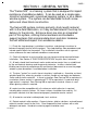
PAGE 1 SECTION I - GENERAL NOTES The "Series 525" is a framing system that is designed for impact resistance of windborne debris. It can be used as a single-span storefront window wall, a punched opening system, or as a ribbon window system. The system can be fabricated for both screw spline and shear block construction. The Series 525 system contains primarily stock length material with in-the-field fabrication, or it may be fabricated in the shop for delivery to the job site.
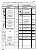
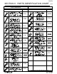
PAGE 2 SECTION II - PARTS IDENTIFICATION CHART VERTICALS DESCRIPTION DOOR FRAMES PART NO. VERTICAL MULLION -SHEAR BLOCK ONLY- VERTICAL MULLION (Deep Pocket) -SCREW SPLINE ONLYUse with 4481 VERTICAL MULLION FILLER (Shallow Pocket) -SCREW SPLINE ONLYUse with 4480 MALE EXPANSION MULLION 4476 -SHEAR BLOCK ONLYUses 4437/9155 door stop and 4487/4488 transom glass stop. 4478 STD. DOOR HEADER 4477 -SHEAR BLOCK ONLYUses 4486 glazing bead. 4484 C.O.C.
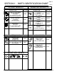
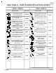
SECTION II - PARTS IDENTIFICATION CHART SHEAR BLOCKS DESCRIPTION HORIZ. & SILL SHEAR BLOCK PACKAGE LH or RH Use with 4475 & 4491 PART NO. K998 K997 (2) FU21, (2) S101, (2) S103, (4) STB5 DOOR HEADER SHEAR BLOCK PKG. LH or RH Use with 4484 & 4483 K876 (1) FV67, (2) STV2, (2) STD8 DESCRIPTION EXTERIOR GLAZING GASKET Used with 9/16" and 5/8" glazing. EXTERIOR GLAZING GASKET Used with 7/16" and 1/2" glazing. EXTERIOR GLAZING GASKET Used with 11/16" glazing. INTERIOR GLAZING GASKET Used with all glazing.
PAGE 4 SECTION II - PARTS IDENTIFICATION CHART (CONT. FASTENERS DESCRIPTION PART NO. DESCRIPTION PART NO.
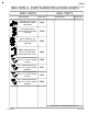
PAGE 5 SECTION II - PARTS IDENTIFICATION CHART MISC. PARTS DESCRIPTION (CONT.) MISC. PARTS PART NO. DESCRIPTION WATER DEFLECTOR @ INT. HORIZONTAL HWD1 BOND BREAKER TAPE 4" X .062" MILL COVER PLATE FOR DORMA RTS 88 C.O.C. AT BUTTS AND CONT. HINGE WM01 (CUSTOMER SPECIFY FINISH) K874 COVER PLATE FOR DORMA RTS 88 C.O.C. AT BUTTS AND CONT. HINGE PART NO. K492 USED @ SUBSILL SPLICES DORMA RTS-88 C.O.C. SUPPORT PKG. FOR BUTT & CONTINUOUS HINGES RHRB DORMA RTS-88 C.O.C. SUPPORT PKG.
PAGE 6 SECTION II - PARTS IDENTIFICATION CHART MISC. PARTS DESCRIPTION (CONT.) MISC. PARTS PART NO. BACKER PLATE & SHIM PACKAGE FOR 180/MP1 TOP PIVOTS K999 LEFT HAND MP2/195 BOTTOM PIVOT BACKER PACKAGE KN04 RIGHT HAND MP2/195 BOTTOM PIVOT BACKER PACKAGE KN05 DOOR JAMB MOUNTING PLATE & SPACER PKG. FOR M19/MP3 INT. PIVOT K968 BUTT HINGE BACKER PKG. FOR 4 1/2 X 4 BUTT HINGES (CLEAR) K900 BUTT HINGE BACKER PKG. FOR 4 1/2 X 4 BUTT HINGES (BRONZE) K901 BUTT HINGE BACKER PKG.
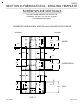
PAGE 7 SECTION III-FABRICATION A - DRILLING TEMPLATE SCREW SPLINE VERTICALS USE THE INTERIOR EDGE OF THE VERTICAL TO ALIGN DRILL JIG DJ20. USE .221 DIA. (#2) DRILL AT DARKENED AREAS ONLY. PERIMETER JAMB SHOWN, VERTICAL MULLION AND FILLER SIMILAR. EXTERIOR INTERIOR 2.312" 2.500" REF. (HEAD) .188" .188" 1.000" 1.000" .188" 1.687" 2.312" 1.000" 2.500" (HORIZONTAL) 2.500" (SILL) 1.000" .188" 1.687" [FIG.
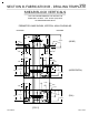
PAGE 8 SECTION III-FABRICATION B - DRILLING TEMPLATE SHEAR BLOCK VERTICALS USE THE INTERIOR EDGE OF THE VERTICAL TO ALIGN DRILL JIG DJ19. USE .182 DIA. (#28) DRILL AT DARKENED AREAS ONLY. PERIMETER JAMB SHOWN, VERTICAL MULLION SIMILAR. EXTERIOR INTERIOR 2.500" .563" .313" .563" .313" .329" (HEAD) .329" 1.000" 1.000" 1.375" 1.000" .625" .329" .375" 1.437" 1.812" 2.125" 2.062" (HORIZONTAL) 2.500" 1.375" 1.000" .625" .329" .375" 1.437" 1.812" 2.125" 2.062" (SILL) 2.500" [FIG.
PAGE 9 SECTION III-FABRICATION C - DRILLING TEMPLATE SHEAR BLOCK HORIZONTALS USE THE INTERIOR & EXTERIOR EDGE AND EACH END OF THE HEAD TO ALIGN DRILL JIG DJ19. USE .228 DIA. (#I) DRILL AT DARKENED AREAS ONLY FOR STEP 1. AFTER STEP 1 IS COMPLETE, PROCEED TO STEP 2. COUNTERSINK HOLES 82˚ TO .438 DIAMETER. (STEP 1) PREP FOR FRAME HEAD. 1.000" 1.000" .625" INTERIOR .625" 4479 HEAD .625" .625" [FIG. 3] EXTERIOR 1.000" 1.000" 82˚ CTSK @ .438 DIA. 1.000" (2) EACH END INTERIOR 1.000" .625" .
PAGE 10 SECTION III-FABRICATION C - DRILLING TEMPLATE (CONT.) SHEAR BLOCK HORIZONTALS USE THE EXTERIOR EDGE AND EACH END OF THE HORIZONTAL OR SILL TO ALIGN DRILL JIG DJ19. USE .228 DIA. (#I) DRILL AT DARKENED AREAS ONLY FOR STEP 1. AFTER STEP 1 IS COMPLETE, PROCEED TO STEP 2. ROTATE THE MATERIAL, AND USE THE EDGE OF THE GLAZING POCKET AND THE END OF EACH HORIZ. OR SILL TO ALIGN DRILL JIG DJ19. USE A .228 DIA. (#I) DRILL AT DARKENED AREAS ONLY FOR STEP 2. PREP FOR FRAME HORIZ. AND SILL (STEP 1) .625" .
PAGE 11 SECTION III-FABRICATION D - SILL WEEP NOTCHES To evacuate water from the system, weep notches must be placed at the ends of each sill. This notch will manifest itself as a 1/8" X 1" notch at each end of the sill, joining the vertical at the exterior face of the sill. The notch also must remove the two extended legs in the middle portion of the sill. These legs must be removed at the same height as the face notch and requires that more material be removed.
PAGE 12 SECTION IV - INTERIOR GASKET INSTALLATION STEP 1) INTERIOR GASKET INSTALLATION After all material is cut to the appropriate length, the WEQ1 interior gasket/sealant backer should be installed. Begin the installation of the WEQ1 by first ensuring that the gasket race is clean and free of debris. The WEQ1 should be cut to the same length as the frame member it is being installed into. Begin the installation on one end of the frame member and slide the WEQ1 into the raceway.
PAGE 13 SECTION V-UNIT ASSEMBLY A - SCREW SPLINE [FIG. 10] DEEP POCKET 4480 4479 STC8 BUTTER THE ENDS OF ALL HORIZONTALS WITH PTI 707 OR EQUIVALENT BUTYL TYPE SEALANT AS SHOWN BY THE SHADED AREAS PRIOR TO ASSEMBLY OF THE UNITS. DEEP POCKET 4481 4491 STC8 STC8 4475 STC8 STC8 EXTERIOR FACE ENSURE THAT EACH MODULE HAS A DEEP GLAZING POCKET ON ONE SIDE AND A SHALLOW GLAZING POCKET ON THE OTHER TO FACILITATE GLAZING INSTALLATION.
PAGE 14 SECTION V-UNIT ASSEMBLY B - SHEAR BLOCK [FIG. 11] 4477 4479 BUTTER THE ENDS OF ALL HORIZONTALS WITH PTI 707 OR EQUIVALENT BUTYL TYPE SEALANT AS SHOWN BY THE SHADED AREAS PRIOR TO ASSEMBLY OF THE UNITS. 4477 K997 HEAD SHEAR BLOCK PKG. (INCLUDES SHEAR BLOCKS AND FASTENERS) 4491 K998 HORIZ. SHEAR BLOCK PKG. (INCLUDES SHEAR BLOCKS AND FASTENERS) 4475 K998 HORIZ. SHEAR BLOCK PKG.
PAGE 15 SECTION VI - DOOR FRAME INSTALLATION STEP 1) GENERAL NOTES Door frames should be installed first, before all other framing material, when required. The system subsill must be installed from the door framing, ensuring that the appropriate clearance is available for the door frame. All subsequent modules must be installed from the door jambs outward. Because of shear block construction methods used with the door framing, the immediate side lites must be shear blocked to the door jambs.
PAGE 16 SECTION VI - DOOR FRAME INSTALLATION (CONT.) STEP 3) SUBSILL SEALANT AT DOOR FRAME Before installing the subsill to the door frame, seal the end of the subsill with Dow Corning 795 or equivalent silicone type sealant. Install the subsill and tool all excess sealant into the joint where the subsill and door jamb meet. If required, add more sealant to create a smooth watertight seal.
PAGE 17 SECTION VI - DOOR FRAME INSTALLATION (CONT.) STEP 4) DOOR HEADER IDENTIFICATION Depending on what type closer is used, two different door headers are available. The header for surface closers has an extruded door stop and will not have a stop applied at the door header. Concealed Overhead Closers (COC) do not have an extruded stop and must have a slide arm cover/door stop applied. The 9914 stop is applied with #8 FH fasteners in prelocated holes.
PAGE 18 SECTION VI - DOOR FRAME INSTALLATION (CONT.) STEP 6) SCREW APPLIED TRANSOM STOP APPLICATION The screw applied vertical transom glass stops should be cut to fit between the top of the door header and the bottom of the transom head. The stop should be attached with STT6 TEK screws 2" from each end and 9" on center Maximum. To facilitate the installation of the door header glass stop, a 3/8" X 3/8" notch must be made on the bottom of the screw applied transom stop.
PAGE 19 SECTION VI - DOOR FRAME INSTALLATION (CONT.) STEP 8) TRANSOM GLASS STOP INSTALLATION When the glass is installed, the door header glass stop should be installed first. Once this is accomplished, the removable transom glazing stops can be installed. The transom glass stops should run from the bottom of the transom head to the top of the door header.
PAGE 20 SECTION VII - SUBSILL FABRICATION & INSTALLATION STEP 1) SUBSILL END DAM REQUIREMENTS Before installing the subsill into the rough opening, you must determine whether an end dam is required or not. If the surrounding condition does not have an open area or can be used as a water dam, move to Step 3 on page 21. The first step to installation of the end dams is to measure the rough opening width. The subsill length should be, ROUGH OPENING WIDTH - 3/8".
PAGE 21 SECTION VII - SUBSILL FABRICATION & INSTALLATION (CONT.) STEP 3) SUBSILL INSTALLATION WHEN END DAMS ARE NOT REQUIRED An end dam may not be required in all cases. Before installing a subsill without an end dam, you must determine if the surrounding condition can be used to create a water dam, and if the material will not degrade over time if it comes into contact with water.
PAGE 22 SECTION VII - SUBSILL FABRICATION & INSTALLATION CLEAN & DEGREASE SILICONE [FIG. 24] SEALANT (CONT.) [FIG. 25] THOROUGHLY STEP 6) ANCHORAGE OF THE SUBSILL After the subsill has been cleaned and the 795 sealant has been applied, rotate the subsill into position and follow the chalk line location marks. Firmly press the subsill into position so that the sealant is pressed uniformly onto the condition.
PAGE 23 SECTION VII - SUBSILL FABRICATION & INSTALLATION (CONT.) STEP 7) SEALING THE ENDS OF THE SUBSILL After the subsill has been installed and anchored, it must be sealed to the condition at each end with 795 or equivalent silicone type sealant. If the subsill has an end dam, there should be a continuous bead of 795 placed up both the interior and exterior and across the top edges of the end dam where it meets the condition.
PAGE 24 SECTION VII - SUBSILL FABRICATION & INSTALLATION (CONT.) STEP 8) SPLICING THE SUBSILL Verify that the subsills have been installed according to instructions on pages 20-23. Splice areas should be centered at the vertical mullion only. Maximum subsill length between splices is 20 feet ±. If a splice is required, leave a 1/4" gap between the subsill ends centered on a vertical mullion location.
PAGE 25 SECTION VIII-FRAME INSTALLATION A. SCREW SPLINE STEP 1) APPLYING SEALANT TO SUBSILL FOR FRAME INSTALLATION Apply 795 or equivalent silicone type sealant to the areas shown in figure 31 below. Do not apply sealant to the sill anchor leg receptor area. Excessive sealant at this area may cause the system to lift up above the subsill and not seat correctly. 795 SEALANT NO SEALANT HERE [FIG. 31] Ensure that enough 795 has been applied to seal the areas shown in figure 32 below.
PAGE 26 SECTION VIII-FRAME INSTALLATION A. SCREW SPLINE (CONT.) STEP 2) INSTALLING JAMB MODULE FOR SCREW SPLINE FRAMES Place the module on the subsill at an approximate 30˚ angle. While applying pressure upward, rotate the module into the condition. See figure 32 on page 25 for sill placement into the subsill. When rotated correctly, the interior face of the sill should be flush against the interior leg of the subsill and the sill should set flat into the subsill as shown in figure 32 on page 25.
PAGE 27 SECTION VIII-FRAME INSTALLATION A. SCREW SPLINE (CONT.) STEP 4) ANCHORING THE HEAD For D.L.O.'s 22" and narrower, the anchors must be spaced 2" from the jamb and vertical members. Also another anchor 4" from the intermediate vertical is required. For D.L.O.'s wider than 22", the outside anchors must be spaced in a similar manner and all center anchors must be located at 16" on center Maximum. See figures 36 and 37 below for anchor placement. These are general anchor location guidelines.
PAGE 28 SECTION VIII-FRAME INSTALLATION A. SCREW SPLINE (CONT.) STEP 5) SEALING SCREW SPLINE VERTICAL MULLIONS Prior to installing an intermediate vertical mullion or perimeter jamb, apply 795 or equivalent silicone type sealant to the vertical mullion in the location shown in figure 38 below. Both sides of the entire mullion should be sealed. Apply enough sealant so when the filler or opposite mullion half is snapped, it will create a good seal. Wipe off excess sealant from the exterior if required.
PAGE 29 SECTION VIII-FRAME INSTALLATION A. SCREW SPLINE (CONT.) STEP 6) INSTALLING SUBSEQUENT SCREW SPLINE MODULES Make sure that the anchors are installed into the head and jamb of the first module as specified in figures 34-37 on page 26 and 27. The 795 sealant should be applied to the mullion and to the subsill as specified in figure 31 on page 25 and in figures 38 and 39 on page 28. Place the second module on the subsill at an approximate 30 degree angle.
PAGE 30 SECTION VIII-FRAME INSTALLATION A. SCREW SPLINE (CONT.) STEP 7) SNAPPING SCREW SPLINE VERTICAL MULLIONS TOGETHER In some cases it may be necessary to use a clamping device to get the mullions together properly, if they cannot be snapped by hand. To do this, place one clamp at the bottom of the mullions using wood blocks to protect the extrusions. Tighten the clamp until the mullion halves begin to snap together.
PAGE 31 SECTION VIII-FRAME INSTALLATION A. SCREW SPLINE (CONT.) STEP 8) ANCHORING SUBSEQUENT SCREW SPLINE MODULES After the mullion halves are snapped correctly, ensure that the mullions are plumb and true, and anchor the head as shown on page 27. If this is the last module in a run, ensure that the mullion halves are snapped correctly and install the required shims between the jamb and condition. Install the head and jamb anchors as shown on pages 26 and 27.
PAGE 32 SECTION VIII-FRAME INSTALLATION B. SHEAR BLOCK (CONT.) STEP 1) INSTALLING SHEAR BLOCK FRAMES Because of the design of the shear blocks for the 525 system, EFCO recommends that the shear block framing be used in punched openings only. It would be possible to stack modules side by side in a longer run. However, the last module could not be installed without an extremely large caulk joint at the jamb of the last module installed.
PAGE 33 SECTION VIII-FRAME INSTALLATION B. SHEAR BLOCK (CONT.) STEP 3) INSTALLING SHEAR BLOCK FRAMES The frame should be supported at each vertical member to ensure the shear block joints are not over stressed. Begin the installation by evenly lifting and supporting the frame so that the bottom of the sill is slightly higher than the top of the subsill. With even pressure, push the frame into the rough opening.
PAGE 34 SECTION VIII-FRAME INSTALLATION C. PERIMETER SEALANT (CONT.) STEP 1) PERIMETER FRAME SEALANT All portions of the frame and surrounding conditions where sealant will be applied should be cleaned and prepped per the sealant manufacturer's recommendations. Use 795 or equivalent silicone type sealant to create the perimeter seal of the system at both exterior and interior perimeters. Exterior and interior seals are required for air and water performance.
PAGE 35 SECTION IX - GLAZING STEP 1) IDENTIFICATION OF SETTING BLOCKS FOR HORIZONTALS The setting block for standard frame horizontals is HN43. Two setting blocks per D.L.O. are required and should be placed at 1/4 points or 1/8 points depending on dead load requirements. Door headers require the use of a HN91 setting block. Two per D.L.O. are also required for the HN91. Depending on dead load requirements, the setting blocks should be placed at 1/4 or 1/8 points.
PAGE 36 SECTION IX - GLAZING (CONT.) STEP 2) SETTING BLOCK LOCATIONS Depending on the size and configuration of each DLO, the glass setting blocks must be placed to give the best support of the glass without adding dead load weight to deflect the horizontal. Figure 56 below shows typical 1/4 point and 1/8 point setting block locations. Contact EFCO Structural Engineering for blocking requirements other than 1/4 and 1/8 points. DLO 8 DLO 8 [FIG.
PAGE 37 SECTION IX - GLAZING (CONT.) STEP 3) GLAZING POCKET IDENTIFICATION IN VERTICALS As instructed in figures 10 and 11 on pages 13 and 14, ensure that each vertical DLO has at least one DEEP glass pocket on either side. It is necessary for the glazing installation that a deep pocket be used to load the glazing units. One exception is the applied transom glazing stops. The applied stops do not require the glass to be loaded into a deep pocket.
PAGE 38 SECTION IX - GLAZING (CONT.) STEP 4) GLASS SIZE FORMULAS AND GLASS BITE Glass size formulas are DLO + 1 1/8" for both horizontal and vertical DLO's. Glass bite for all glazing is 9/16". See figures 63-65 below for glass size and bite. DOOR JAMB JAMB JAMB SS VERT. 4476 TRANSOM STOP SB VERT. 4480 4476 4477 4478 4481 4478 4487 4487 4488 9/16" 9/16" 9/16" 9/16" BITE 9/16" BITE 9/16" BITE 9/16" BITE BITE BITE BITE DLO DLO DLO 9/16" BITE DLO [FIG.
PAGE 39 SECTION IX - GLAZING (CONT.) STEP 5) INSTALLING THE HWD1 WATER DEFLECTOR The HWD1 water deflector is designed to be used with several EFCO storefront systems. For this reason, the deflector needs to be modified to fit the 525 system glazing pockets. See figure 66 to the right for HWD1 modification. THE MODIFIED END OF THE HWD1 FITS INTO THE VERTICAL GLASS POCKET OF THE 525 FRAMING. HWD1 USE CUTTERS TO REMOVE @ "V" GROOVES ONE SIDE ONLY [FIG.
PAGE 40 SECTION IX - GLAZING (CONT.) STEP 6) GLASS INSTALLATION A) Make sure that the HWD1 is installed per the instructions in figures 66-68 on page 39. B) Position the glass on the exterior of the frame without the removable glass stop installed. Shift the glass into the deep pocket to begin the installation. C) Swing the opposite edge of the glass around to align the glass with the glazing pocket.
PAGE 41 SECTION IX - GLAZING (CONT.) STEP 7) EXTERIOR GLAZING GASKET INSTALLATION Ensure that the glass, setting blocks, and snap in glazing bead have been installed according to the instructions in figures 69 and 70 on page 40. Begin by measuring the DLO width and height. Cut the exterior glazing gasket to length by using the following formula. EXTERIOR GASKET LENGTH = DLO DIM. X 1.02 or (DLO DIM. + 2%) To install the exterior gasket, start by pushing the precut gasket in place at the ends.
PAGE 42 SECTION IX - GLAZING (CONT.) STEP 8) INTERIOR GLASS SEALANT APPLICATION Begin the interior glass sealant application by ensuring that the glass and metal are cleaned and dry per the sealant manufacturer's instructions. Apply sufficient Dow Corning 995 or equivalent structural silicone sealant to the gap between the glass and metal to fill the void back to the interior gasket on all sides of each DLO.
PAGE 41 SECTION IX - GLAZING (CONT.) STEP 7) EXTERIOR GLAZING GASKET INSTALLATION Ensure that the glass, setting blocks, and snap in glazing bead have been installed according to the instructions in figures 69 and 70 on page 40. Begin by measuring the DLO width and height. Cut the exterior glazing gasket to length by using the following formula. EXTERIOR GASKET LENGTH = DLO DIM. X 1.02 or (DLO DIM. + 2%) To install the exterior gasket, start by pushing the precut gasket in place at the ends.