Series 526 Thermal impact storefront Installation Instructions Part NO.
Series 526 Impact Installation Instructions TABLE OF CONTENTS SECTION PAGE I. General Notes and Guidelines….…………………………………………3 II. Parts Identification Chart……….…...……………………………………...4-8 III. Fabrication…………………………………..……………………………...9-16 IV. Frame Assembly…….....………………………………………….……….17-20 V. Door Frame Installation…………...……...……………………………….21-23 VI. Subsill Fabrication and Installation…..…………………………….....….24-29 VII. Frame Installation………………………..….……………………………..30-36 VIII. Glazing………….…….
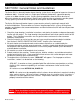
Series 526 Impact Installation Instructions SECTION I: General Notes and Guidelines The Series 526 is a thermally broken impact framing system that is designed for impact resistance of windborne debris. It can be used as a single-span storefront window wall, a punched opening system, or a ribbon window system. Various glazing capabilities allow the 526 to be used as either wet sealed or dry gasket glazed. Both the wet sealed and the dry glazed are outside glazed.
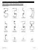
Series 526 Impact Installation Instructions SECTION II: Parts Identification Chart Vertical Parts: 16G1 16G8 16G9 16H3 Perimeter Jamb Vertical Mullion Mates With 16G9 Vertical Mullion Filler Mates With 16G8 Door Jamb Mates With 16H6 16H6 16H9 16J5 16K6 Door Jamb Filler with Deep Pocket Mates With 16H3 Female Expansion Mullion Shallow Pocket Mates With 16J5 Male Expansion Mullion Deep Pocket Mates With 16H9 Vertical Mullion _Shear Block Only- 16H8 4488 4437 9155 Vertical Applied Glass S
Series 526 Impact Installation Instructions SECTION II: Parts Identification Chart Horizontal Parts: 4G77 4G78 16H2 16G2 Outside Glaze Sill Use With 4G79 Inside Glaze Sill Use With 4G79 Horizontal Use With 16G3 & 16G4 Head Use With 16G3 & 16G4 4G79 4G80 4G81 4G82 Subsill Use With 4G77, 4G78, 4G81 & 4G82 4 1/2” Subsill Use With 4G81 & 4G82 Outside Glaze 4 1/2” Sill Use With 4G79 & 4G80 Inside Glaze 4 1/2” Sill Use With 4G79 & 4G80 16H4 16H5 16H7 16G3 Door Header Use 16H7 Stop & 9914 Doo
Series 526 Impact Installation Instructions SECTION II: Parts Identification Chart Shear Blocks: KP01 K876 KP04 KP03 Head & Horizontal Shear Block Package Use With 16H2 & 16G2 Door Header Shear Block Package Use With 16H4 & 16H5 Shear Block Package With Shim for Horizontal Thru Use With 16K6 Shear Block Package for Horizontal Thru Use With 16K6 Setting Blocks: HEP0 HN13 Sill & Horizontal Setting Blocks Door Header Setting Block Glazing Gasket: W146 W167 WEQ1 Dry Glazed Preset Gasket Driv
Series 526 Impact Installation Instructions SECTION II: Parts Identification Chart Fasteners: STC8 SDR1 STT6 S130 #12-14 X 1 1/4 PH-SMS 18-8 25 #10-16 X 3/4 PH-SMS SG TEK/2 #8-18 X 9/16 PH-SMS ZC TEK/2 #8-15 X 1 3/4 PH-SMS 18-8 A Drill Jigs: DJ28 DJ29 Screw Spline Drill Jig Shear Block Drill Jig Miscellaneous: FWB0 KP00 KP10 HC03 WM01 Water Deflector Use @ 16H2 Subsill End Cap Use @ 4G79 4 1/2” Subsill End Cap Use @ 4G80 Subsill Isolator Use @ 4G77, 4G78, 4G81, & 4G82 Bond Breaker T
Series 526 Impact Installation Instructions SECTION II: Parts Identification Chart Miscellaneous: KP11 KP08 KP07 K435 FT16 3-Point Impact Lock Strike Package Dorma RTS-88 C.O.C. Support PKG. for Butt & Cont. Hinges Dorma RTS-88 C.O.C. F-Clip Spacer PKG. for Butt & Cont. Hinges Attachment Clip for Dorma RTS-88 C.O.C. F-Clip Spacer PKG. for Offset Pivots F-Clip for Dorma RTS-88 C.O.C.
Series 526 Impact Installation Instructions SECTION III: Fabrication A. Drilling Template for Screw Spline at Verticals Outside Glazed Use the interior or exterior edge of the vertical to align drill jig, DJ28. Drill with a .221 dia. (#2) drill at darkened areas only. Dimension taken from top of head. 526 SCREW SPLINE Dimension taken from top of horizontal. 526 SCREW SPLINE Dimension taken from top of sill.
Series 526 Impact Installation Instructions SECTION III: Fabrication B. Drilling Template for Screw Spline at Verticals Outside Glazed (4 1/2” Sill) Use dimensions as shown, or cut a short piece of the sill material and use as a template. Drill with a .221 dia. (#2) drill at darkened areas only. Dimension taken from top of sill.
Series 526 Impact Installation Instructions SECTION III: Fabrication C. Drilling Template for Screw Spline at Verticals Inside Glazed Use the interior or exterior edge of the vertical to align drill jig, DJ28. Drill with a .221 dia. (#2) drill at darkened areas only. Dimension taken from top of head. 526 SCREW SPLINE Dimension taken from top of horizontal. 526 SCREW SPLINE Dimension taken from top of sill.
Series 526 Impact Installation Instructions SECTION III: Fabrication D. Drilling Template for Screw Spline at Verticals Inside Glazed (4 1/2” Sill) Use dimensions as shown or cut a short piece of the sill material to use as a template. Drill with a .221 dia. (#2) drill at darkened areas only. Dimension taken from top of sill.
Series 526 Impact Installation Instructions SECTION III: Fabrication E. Drilling Template for Shear Blocks at Verticals Outside Glazed Use the interior or exterior edge of the vertical to align drill jig, DJ29. Drill with a .182 dia. (#28) drill at darkened areas only. Dimension taken from top of head. 526 SHEAR BLOCK Dimension taken from top of horizontal.
Series 526 Impact Installation Instructions SECTION III: Fabrication F. Drilling Template for Shear Blocks at Verticals Inside Glazed Use the interior or exterior edge of the vertical to align drill jig, DJ29. Drill with a .182 dia. (#28) drill at darkened areas only. Dimension taken from top of head. 526 SHEAR BLOCK Dimension taken from top of horizontal.
Series 526 Impact Installation Instructions SECTION III: Fabrication G. Drilling Template for Shear Blocks at Head and Horizontal Inside Glazed and Outside Glazed Align drill jig, DJ29, flush to the end of the head or horizontal. Drill with a .221 dia. (#2) drill at darkened areas only.
Series 526 Impact Installation Instructions SECTION III: Fabrication H. Drilling Template for Shear Blocks at Horizontal Use When Vertical Runs Between Horizontal Use dimensions as shown when a vertical runs between horizontals. Drill with a .180 dia. (#15) drill at darkened areas only. This fabrication works with vertical attaching to either the head, horizontal, or sill.
Series 526 Impact Installation Instructions SECTION IV: Frame Assembly A. Preset Gasket Installation for Dry Glazed and Wet Glazed After all the material is cut to the appropriate length, the preset gasket should be installed. Begin the installation of the preset gasket by first ensuring that the gasket race is clean and free of debris. The preset gasket should be cut longer than the frame member it is being installed into. Lay the preset gasket down the length the frame member.
Series 526 Impact Installation Instructions SECTION IV: Frame Assembly B. Screw Spline Assembly Inside Glazed and Outside Glazed Each module must have at least one deep pocket vertical to facilitate glazing installation. See page 39 for more detail on glazing pockets. Apply sealant to both ends of all horizontals prior to assembling the module. After module is assembled, clean off all excess butyl sealant.
Series 526 Impact Installation Instructions SECTION IV: Frame Assembly C. Door Frame Shear Block Assembly Outside Glazed Only Apply sealant to both ends of all the horizontals prior to assembling the module. After module is assembled, clean off all excess butyl sealant. Shear block packages come with shear blocks and fasteners. Prior to applying sealant to the required areas, clean the area with Isopropyl Alcohol and a clean towel that will not leave towel materials behind.
Series 526 Impact Installation Instructions SECTION IV: Frame Assembly D. Horizontal Thru Shear Block Assembly Inside Glazed and Outside Glazed Apply butyl type sealant to both ends of the vertical prior to assembling the module. After module is assembled, clean off all excess butyl sealant. Shear block packages come with shear blocks and fasteners. Prior to applying sealant to the required areas, clean the area with Isopropyl Alcohol and a clean towel that will not leave towel materials behind.
Series 526 Impact Installation Instructions SECTION V: Door Frame Installation Step 1) General Notes Door frames should be installed first, before all other framing material. The system subsill must be installed from the door framing, ensuring that the appropriate clearance is available for the door frame. All subsequent modules must be installed from the door jambs outward. The door frame module is shear block only. All sidelites will be screw spline application. Door jambs do not set on the subsill.
Series 526 Impact Installation Instructions SECTION V: Door Frame Installation Step 3) Subsill Sealant at Door Frame Before installing the subsill to the door frame, seal the end of the subsill with a silicone type sealant. Install the subsill, and tool all excess sealant into the joint where the subsill and door jamb meet. If required, add more sealant to create a smooth watertight seal.
Series 526 Impact Installation Instructions SECTION V: Door Frame Installation Step 4) Door Header Identification Depending on what type closer is used, two different door headers are available. The header for surface closers has an extruded door stop and will not have a stop applied at the door header. Concealed Overhead Closers (COC) do not have an extruded stop and must have a slide arm cover/door stop applied. The 9914 stop is applied with S130 #8 FH fasteners in pre-located holes.
Series 526 Impact Installation Instructions SECTION VI: Subsill Fabrication and Installation Step 1) Subsill End Dam Requirements Before installing the subsill into the rough opening, determine whether an end dam (KP00) is required or not. If the surrounding condition does not have an open area or can be used as a water dam, move to Step 3 on page 25. The first step to installation of the end dams is to measure the rough opening width. The subsill length should be, ROUGH OPENING WIDTH - 3/8".
Series 526 Impact Installation Instructions SECTION VI: Subsill Fabrication and Installation Step 3) Subsill Weep Fabrication Drill 3/8” weep holes in subsill 6” from each jamb/vertical and no more than 42” apart. [Fig. 8] Step 4) Subsill Weep Baffle Installation Weep baffles (FWE5) are placed on the subsill behind the weep holes. Apply a small amount of silicone type sealant to the baffles, and locate them over the weep holes as shown in figure 9. Ensure the sealant does not cover the weep holes. [Fig.
Series 526 Impact Installation Instructions SECTION VI: Subsill Fabrication and Installation Step 6) Benchmarks for Subsill Location Before installing the subsill, the exterior face location of the frame should be found using benchmark information from the shop drawings or architectural drawings. The subsill protrudes 1/32" to the exterior of the exterior face of the frame. Locate this line based on the benchmark information, and snap a chalk line to follow when installing the subsill.
Series 526 Impact Installation Instructions SECTION VI: Subsill Fabrication and Installation Step 7A) Shimming the Subsill if Required In cases where the sill condition is not true and level, shimming may be required. The subsill must be level and true and will need to be prepped as described in Step 7 on page 26. At the shimmed area, there is no need to apply sealant until after the subsill is set on the condition and anchored as described in Step 8. See figures 14 and 15. [Fig. 12] [Fig.
Series 526 Impact Installation Instructions SECTION VI: Subsill Fabrication and Installation Step 9) Sealing the Ends of the Subsill After the subsill has been installed and anchored, it must be sealed to the condition at each end with silicone type sealant. If the subsill has an end dam, there should be a continuous bead of silicone type sealant placed up both the interior and exterior and across the top edges of the end dam, where it meets the condition.
Series 526 Impact Installation Instructions SECTION VI: Subsill Fabrication and Installation Step 10) Splicing the Subsill Verify that the subsills have been installed according to instructions on pages 24-28. Splice areas should be centered at the vertical mullion only. Subsill length should never exceed 20-25 feet. If a splice is required, leave a 1/4" gap between the subsill ends centered on a vertical mullion location. See figure 18.
Series 526 Impact Installation Instructions SECTION VII: Frame Installation Step 1) Installing Sill Isolator Before installing the jamb module into the opening, the sill isolator (HC03) must be in place. Slide the isolator onto the interior interlock leg on the sill. See figure 21 below. There will need to be one at each end of the sill at quarter points. Place a small amount of sealant on the interlock leg at the quarter point location to hold the isolator in place while installing the module. [Fig.
Series 526 Impact Installation Instructions SECTION VII: Frame Installation Step 3) Anchoring the Jamb Ensure that the frame jamb is true and plumb. Anchor through the jamb and into the condition as shown in figures 24 and 25 below. As a general guideline, anchors will be located 2” from head and sill with a maximum of 16” O.C. and 1/2” shimming. Remember these are general anchor location guidelines.
Series 526 Impact Installation Instructions SECTION VII: Frame Installation Step 4) Anchoring the Head For D.L.O.s 22" and narrower, the anchors must be spaced 2" from the jamb and vertical members. Also, another anchor 4" from the intermediate vertical is required. For D.L.O.s wider than 22", the outside anchors must be spaced in a similar manner, and all center anchors must be located at 16" on center maximum. See figures 26 and 27 below for anchor placement.
Series 526 Impact Installation Instructions SECTION VII: Frame Installation Step 5) Sealing Vertical Mullions Prior to installing an intermediate vertical mullion or perimeter jamb, apply silicone type sealant to the vertical mullion in the location shown in figure 28 below. Both sides of the entire mullion should be sealed. Apply enough sealant so when the filler or opposite mullion half is snapped, it will create a good seal. Wipe off excess sealant from the exterior, if required.
Series 526 Impact Installation Instructions SECTION VII: Frame Installation Step 6) Installing Subsequent Modules Make sure that the anchors are installed into the head and jamb of the first module as specified in figures 24-27 on pages 31 and 32. The silicone type sealant should be applied to the mullion as specified in figure 28 on page 33. Place the second module on the subsill at an approximate 30 degree angle. See figure 30 below.
Series 526 Impact Installation Instructions SECTION VII: Frame Installation Step 7) Snapping Screw Spline Vertical Mullions Together In some cases, it may be necessary to use a clamping device to get the mullions together properly, if they cannot be snapped by hand. To do this, place one clamp at the bottom of the mullions using wood blocks to protect the extrusions. Tighten the clamp until the mullion halves begin to snap together.
Series 526 Impact Installation Instructions SECTION VII: Frame Installation Step 7) Perimeter Frame Sealant All portions of the frame and surrounding conditions, where sealant will be applied, should be cleaned and prepped per the sealant manufacturer's recommendations. Use silicone type sealant to create the perimeter seal of the system at both exterior and interior perimeters. Exterior and interior seals are required for air and water performance.
Series 526 Impact Installation Instructions SECTION VIII: Glazing Step 1) Setting Block Identification and Location The setting block for standard frame horizontals is HEP0. The door headers require the use of a HN13 setting block. Two setting blocks per D.L.O. are required and should be placed at 1/4 points or 1/8 points, depending on special dead load requirements.
Series 526 Impact Installation Instructions SECTION VIII: Glazing Step 2) Glazing Pocket Identification in Verticals Ensure that each vertical DLO has at least one DEEP glass pocket on either side. It is necessary for the glazing installation that a deep pocket be used to load the glazing units. One exception is the applied transom glazing stops. The applied stops do not require the glass to be loaded into a deep pocket.
Series 526 Impact Installation Instructions SECTION VIII: Glazing Step 3) Glass Size Formulas and Glass Bite (Verticals) Glass size formulas are D.L.O. + 1 1/8" for both horizontal and vertical D.L.O.s. Glass bite for all glazing is 9/16". See figure 38 below for horizontal glass size and bite and figure 39 on the next page for vertical glass size and bite. JAMB S.S. VERTICAL D.L.O. D.L.O. 9/16 D.L.O. DOOR JAMB VERT. FILLER D.L.O. 9/16 9/16 9/16 9/16 EXPANSION VERTICAL S.B.
Series 526 Impact Installation Instructions SECTION VIII: Glazing Step 3A) Glass Size Formulas and Glass Bite (Horizontals) [Fig. 39] HEAD HEAD 9/16 D.L.O. 9/16 D.L.O. + 1 1/8 HORIZONTAL D.L.O. D.L.O. + 1 1/8 DOOR HEADER 9/16 9/16 9/16 D.L.O. + 1 1/8 D.L.O.
Series 526 Impact Installation Instructions SECTION VIII: Glazing Step 4) Installing the FWB0 Water Deflector Install the FWB0 at the ends of the intermediate horizontals only. It is not required at heads or sills. Use silicone type sealant to adhere the FWB0 on the intermediate horizontal. Ensure that the thermal cavity is filled with sealant. Place FWB0 onto the top of the intermediate horizontal glazing pocket, and smooth any excess sealant so water will flow easily over the water deflector.
Series 526 Impact Installation Instructions SECTION VIII: Glazing Step 5) Installing the Door Transom Glazing Adaptor Before installing the transom glazing adaptor (16H8), it has to be fabricated. The cut length is transom D.L.O. Transom D.L.O. is measured from top of door header to bottom of transom head as shown in figure 39 on page 40. To facilitate the installation of the door header glass stop, notch both ends of the adaptor with a 1/2” X 7/16” notch as shown below. Drill a .201 dia.
Series 526 Impact Installation Instructions SECTION VIII: Glazing Step 5A) Installing the Door Transom Glazing Adaptor The preset gasket will need to be pulled out of the corners or removed completely before starting to install the 16H8 glazing adaptor. Run a bead of sealant from the bottom of the head, down the interior edge of the glazing adaptor pocket, and across the pocket at the top of the door header. Attach the glazing adaptor using SDR1 (10-16 X 3/4 TEK) fasteners.
Series 526 Impact Installation Instructions SECTION VIII: Glazing Step 6) Glass Installation A. Make sure that the FWB0 is installed per the instructions on page 41. B. Clean the ends of the horizontal preset gasket with alcohol. Clean the vertical, where the horizontal butts up against it, with alcohol. Apply sealant to the end of the horizontal so that it will create a seal when it butts against the vertical. C. Insert the setting blocks at the predetermined 1/4 or 1/8 point locations. D.
Series 526 Impact Installation Instructions SECTION VIII: Glazing Step 7) Attaching Glass Stop and Glass Stop Cover The 16G3 glass stop has a hook leg that has to go past the frame hook leg towards the glass. So,it is necessary to push the glass against the preset gasket. This will give the 16G3 leg enough clearance of the frame hook leg. Lift and pull into place. It may be necessary to use short pieces of the drive-in gasket (W167) to temporarily hold it in place.
Series 526 Impact Installation Instructions SECTION VIII: Glazing Step 8) Anti-Walk Block Installation Stretch the anti-walk block out as flat as possible, and insert it in between the glass and frame so that it opens up inside the glass pocket at midspan of the D.L.O. at the deep pocket. See figure 50 below. This can only be done from the drive-in gasket side of the frame.
Series 526 Impact Installation Instructions SECTION VIII: Glazing Step 9) Drive-in Glazing Gasket Installation Ensure that the glass, setting blocks, snap-in glazing bead, and anti-walk blocks have been installed according to the instructions on the previous pages. Begin by measuring the D.L.O. width and height. Cut the drive-in glazing gasket (W167) to length by using the following formula. EXTERIOR GASKET CUT LENGTH = D.L.O. DIM + 2% (D.L.O. DIM X 1.
Series 526 Impact Installation Instructions SECTION VIII: Glazing Step 10) Inside Glazed Glass Stop Seal (Dry Glazed Only) After installing the 16G3 glass stop, run a bead of silicone type sealant across the seam of the glass stop and jamb, then fill the gasket raceway with sealant. Tool the sealant to make a watertight seal. See figure 53 below. [Fig. 53] Sealant to follow the profile of the glass stop.
Series 526 Impact Installation Instructions SECTION VIII: Glazing Step 11) Appling the Glass Stop Cover The glass stop cover (16G4) is snapped in place after the drive-in gasket is glazed. It may be necessary to use a soft face mallet to snap the cover into place. Start by pressing the cover down so that it will clear the frame snap leg, then run it to the other end. [Fig. 54] Press the cover snap leg past the frame snap leg. Hit with a soft face mallet at this corner.
Series 526 Impact Installation Instructions SECTION VIII: Glazing Step 12) Wet Glazed Application (Outside Glazed Only) When glazing a wet glazed unit, follow all the previous instructions in this manual and substitute the W146 gasket with WEQ1. Begin the interior glass sealant application by ensuring that the glass and metal are cleaned and dry per the sealant manufacturer's instructions.