Series 5800 E-wall silicone gasket curtain wall system Installation instructions Part NO.
Minimizing Condensation Note: Please reference EFCO's "Understanding Condensation" brochure which can be obtained through your EFCO representative. Condensation will form on any surface when unfavorable conditions (interiro temperature and relative humidity and exterior temperature) are present.
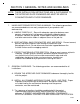
PAGE 1 SECTION I: GENERAL NOTES AND GUIDELINES NOTE: THESE INSTALLATION INSTRUCTIONS ARE A SUPPLEMENT TO THE APPROVED SHOP DRAWINGS AND MUST BE USED IN CONJUNCTION WITH THOSE DRAWINGS. 1. HANDLING/STORING/PROTECTING ALUMINUM - The following precautions are recommended to assure early acceptance of your products and workmanship. A. HANDLE CAREFULLY - Store with adequate separation between components so material will not become scratched or rubbed at points of contact. Store off the ground.
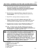
PAGE 2 SECTION I: GENERAL NOTES AND GUIDELINES CONT. D. Verify that all job site conditions and accompanying substrates receiving the installation are in accordance with the contract documents. If deviations occur, notification must be given IN WRITING to the general contractor and differences resolved before proceeding further with the installation in the questionable area. E.
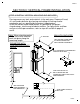
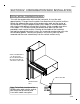
PAGE 3 SECTION II: VERTICAL FRAME INSTALLATION STEP #1 INSTALL VERTICAL MULLIONS AND ANCHORS Prestage necessary tools and materials in the work area. Prepare all head, sill, and jamb substrates by cleaning and setting all flashings and/or membrane seals as specified by the project shop drawings. Insert the mullion and/or head anchor, as specified by the project shop drawings, into the end of tubular mullions.
PAGE 4 SECTION II: VERTICAL FRAME INSTALLATION STEP #2 APPLY MIDSPAN FLOOR ANCHORS Attach the midspan floor anchors to the mullions with temporary alignment screws. Set the vertical mullion in place, plumb and true. Make permanent attachment of base anchors, head anchors, and midspan floor anchors to the building structure as specified in the approved project shop drawings. After completing permanent anchorage, remove all temporary alignment screws and fasteners.
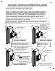
PAGE 5 SECTION II: VERTICAL FRAME INSTALLATION CONT. STEP #3 INSTALL VERTICAL SPLICE JOINTS Splice joints should occur at spandrel areas (if possible). Refer to approved shop drawings for actual locations. Splice sleeves will be shop assembled in the top of the lower mullion. GENERAL NOTE: The following details depicts a splice joint of 1/2". The required joint width must be determined at the design stage and shown on the approved shop drawings, on a job by job basis.
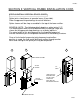
PAGE 6 SECTION III: HORIZONTAL FRAME INSTALLATION STEP #1 PLUG ENDS OF PERIMETER HORIZONTALS Prior to horizontal attachment, insert a 2 1/2" piece of backer rod folded to 90 degree into the jamb end of the head and sill horizontals. Seal the ends with silicone to create an end plug. The end plug will act as a back-up for the perimeter seal later.
PAGE 7 SECTION III: HORIZONTAL FRAME INSTALLATION CONT. STEP #3 INTERMEDIATE HORIZONTALS Attach the appropriate horizontal member to the vertical mullion at the notch with (2) Stalgard, #10-16 x 3/4", PL-PH-SMS, Tek/2, self drilling fasteners through predrilled holes in the ends of each horizontal member. Confirm the mullion center line to center line dimension at each horizontal installation before and after fastening the horizontal in place.
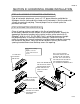
PAGE 8 SECTION IV: CONDENSATION WICK INSTALLATION STEP #1 INSTALL CONDENSATION WICK To install the condensation wick into the horizontal, first cut the wick approximately 3" longer than the center line dimension of the vertical mullions. Locate the approximate center of the condensation wick and the center of the horizontal. Using the deglazing tool, press about 6" of the condensation wick into the wick pocket, leaving each end free.
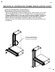
PAGE 9 SECTION V: GLAZING ADAPTOR INSTALLATION STEP #1 INSTALL GLAZING ADAPTORS Locate and insert the glazing adaptors for openings that have a glazing thickness of less than 1". Horizontal adaptors run through and must be inserted first at the top and bottom of each light. Horizontal adaptors are cut shorter than the opening dimension. Locate and insert the adaptor in the center of the space provided, allowing equal distance between each end.
PAGE 10 SECTION VI: INTERIOR GASKET INSTALLATION STEP #1 INSTALL HORIZONTAL GASKET Cut the specified interior horizontal gasket 1 3/4" longer than the daylight opening width. Center the gasket on the horizontal member and press straight into the gasket pocket. STEP #2 INSTALL VERTICAL GASKET Cut the interior vertical gasket 1/8" longer than the daylight opening. Center the gasket on the vertical opening and press straight into the gasket pocket. Allow the horizontal gasket to run through.
PAGE 11 SECTION VII: GLAZING INSTALLATION STEP #1 INSTALL GLAZING MATERIALS Verify that all gasket retainer pockets are free from dirt and foreign matter. Place the specified setting blocks and antiwalk blocks as shown in the approved project shop drawings. Set the specified glazing infill into the corresponding opening, ensuring positive bearing on the setting blocks and an equal glass bite at all sides of the infill panel. The typical glass bite should be 9/16" in a 2 1/2" wide system.
PAGE 12 SECTION VIII: EXTERIOR GASKET INSTALLATION STEP #1 TEMPORARY GASKET INSTALLATION Depending on your sequence of installation, you may or may not want to use temporary glazing retainers to hold the glass in place until the final gasket installation can be achieved. To allow for temporary installation, 12" long gasket retainers can be provided for your use. Temporary retainers should be positioned in the center of any glass edge that is less than 30" long and at quarter points for edges over 30".
PAGE 13 SECTION VIII: EXTERIOR GASKET INSTALLATION CONT. STEP #3 GASKET INSTALLATION AND INSPECTION Select a formed corner gasket corresponding to the opening in process and lubricate with the recommended gasket lubricant. Position the gasket to the opening and install the gasket corner darts into the retainer pockets at the top corners of the opening, using a #HM46 dead blow mallet (see illustration "A" on page #14).
PAGE 14 SECTION VIII: EXTERIOR GASKET INSTALLATION CONT. STEP #4 STEP BY STEP GASKET INSTALLATION Align the center of the linear sides of the gasket with the center line of the opening. Use the #HM46 mallet to engage the gasket dart into the gasket retainer pocket at this half point. See illustration "B" below. Continue to install the gasket by dividing the remaining loose gasket material in half and work it into the gasket retainer pocket. See illustration "C" below.
PAGE 15 SECTION VIII: EXTERIOR GASKET INSTALLATION CONT. BEFORE ADJUSTMENT INCORRECT GASKETS DO NOT ALIGN PROPERLY. AFTER ADJUSTMENT CORRECT ALL GASKET CORNERS LINE UP. NOTE: Feel the gasket surface to ensure it is smooth and flat.
PAGE 16 SECTION VIII: EXTERIOR GASKET INSTALLATION CONT. STEP #6 PERIMETER GASKET INSTALLATION At very large openings, a butt joint may be required to facilitate handling and installation. A butt joint in the perimeter gasket will generally occur at center of daylight opening. Install the gasket at the opening corners per the typical gasket installation. Clean each gasket end. A factory cut end will be provided.
PAGE 17 SECTION IX: PERIMETER SEAL INSTRUCTIONS STEP #1 PERIMETER SEAL INSTRUCTIONS Insert the specified backer material into the perimeter joint and apply perimeter sealant continuously to the prepared substrate and previously cleaned surface of the system framing. Professionally tool the sealant joint to verify that a continuous sealant contact is between the frame and substrate. Perimeter seals can be fully applied before or after the system is glazed.
PAGE 18 SECTION X: DEGLAZING PROCEDURE STEP #1 GASKET REMOVAL If the glazing must be removed, use the following procedure. Insert the deglazing tool provided directly between the gasket intersection point, at the corner. Insert the point of the tool directly down until the point hits the back of the vertical gasket retainer pocket. Using a prying motion, rotate the point of the deglazing tool until the curved back portion seats against the gasket retainer pocket.