Flat Wall Assembly Instructions Volume 1 of 6 - Sections 1 - 3 July 2011 PART NO.
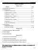
Table of Contents Volume 1 of 6 SECTION PAGE 1. General Notes and Guidelines………………………………………………………….. 4 - 5 2. Parts Identification A. Fasteners and accessories……………………………………………………… 6 - 8 B. Frame Extrusions - 7” System....................................................................... 9 - 10 C. Extrusions - 7” system................................................................................... 11 D. Frame Extrusions - 8” System.......................................................................
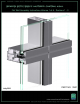
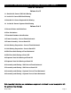
Series 8700 / 8800 Unitized Curtain Wall Assembly Instructions - Volume 1 EFCO 2009 Series 8700 / 8800 Unitized Curtain Wall Assembly Instructions - Volume 1 Table of Contents Volume 4 of 6 11. Outside 90° Corner SSG Unit Glazing 12. Inside 90° Corner SSG Unit Glazing 13. Outside 90° Corner Captured Unit Glazing 14. Inside 90° Corner Captured Unit Glazing Volume 5 of 6 15. General Notes and Guidelines 16. Size Limitations 17. Standard Hardware Identification 18.
Series 8700 / 8800 Unitized Curtain Wall Assembly Instructions - Volume 1 TableWall of Contents Series 8700 / 8800 Unitized Cutain Assembly Instructions - Volume 1 Volume 5 of 6 30. Hardware Mounting On Unit Assembly 31. Hardware Mounting On Sash 32. Mounting Vent Assembly Into Unit Assembly Volume 6 of 6 33. Shadow Box Assembly 34. Shadow Box Installation 35. Shadow Box Insulation Installation 36. Back Panel Installation 37. Back Panel Insulation Installation 38.
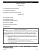
Series 8700 / 8800 Unitized Curtain Wall Assembly Instructions - Volume 1 Section 1 - General Notes And Guidelines HANDLING / STORING / PROTECTING ALUMINUM The following guidelines are recommended to ensure early acceptance of your products and workmanship. A. HANDLE CAREFULLY - Store with adequate separation between components so the material will not rub together. Store the material off the ground. Protect materials against weather elements and other construction trades. B.
Series 8700 / 8800 Unitized Curtain Wall Assembly Instructions - Volume 1 Section 1 - General Notes And Guidelines recommendations for primers and substrate preparation required to obtain adhesion. The chemical compatibility of all glazing materials and framing sealants with each other and with like materials used in glass fabrication must be established. Maintain caulk joints as shown in the approved shop drawings.
Series 8700 / 8800 Unitized Curtain Wall Assembly Instructions - Volume 1 Section 2 - Parts Identification : A.
Series 8700 / 8800 Unitized Curtain Wall Assembly Instructions - Volume 1 Section 2 - Parts Identification : A.
Series 8700 / 8800 Unitized Curtain Wall Assembly Instructions - Volume 1 Section 2 - Parts Identification : A.
Series 8700 / 8800 Unitized Curtain Wall Assembly Instructions - Volume 1 Section 2 - Parts Identification : A.
Series 8700 / 8800 Unitized Curtain Wall Assembly Instructions - Volume 1 Section 2 - Parts Identification : A.
Series 8700 / 8800 Unitized Curtain Wall Assembly Instructions - Volume 1 Section 2 - Parts Identification : B.
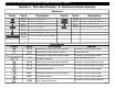
Series 8700 / 8800 Unitized Curtain Wall Assembly Instructions - Volume 1 Section 2 - Parts Identification : B. Frame Extrusions - 7" System Frame Extrusions - 7" System Profile Description 17B0 7" CAPTURED AND SSG HORIZONTAL STACK SILL CUT TO LENGTH (D.L.O.) AT TYPICAL FLAT UNITS 17D7 7" CAPTURED AND SSG HEAD HORIZONTAL CUT TO LENGTH (D.L.O.) AT TYPICAL FLAT UNITS 17D8 7" CAPTURED AND SSG HEAD HORIZONTAL FILLER CUT TO LENGTH (D.L.O.) MINUS .
Series 8700 / 8800 Unitized Curtain Wall Assembly Instructions - Volume 1 Section 2 - Parts Identification : C.
Series 8700 / 8800 Unitized Curtain Wall Assembly Instructions - Volume 1 Section 2 - Parts Identification : D.
Series 8700 / 8800 Unitized Curtain Wall Assembly Instructions - Volume 1 Section 2 - Parts Identification : D. Frame Extrusions - 8" System Frame Extrusions - 8" System Profile Tooling/Cut Length Formula Part # Description 17H0 8" CAPTURED AND SSG HORIZONTAL STACK SILL CUT TO LENGTH (D.L.O.) AT TYPICAL FLAT UNITS 17H3 8" CAPTURED AND SSG HEAD HORIZONTAL CUT TO LENGTH (D.L.O.) AT TYPICAL FLAT UNITS 17H4 8" CAPTURED AND SSG HEAD HORIZONTAL FILLER CUT TO LENGTH (D.L.O.) MINUS .
Series 8700 / 8800 Unitized Curtain Wall Assembly Instructions - Volume 1 Section 2 - Parts Identification : E.
Series 8700 / 8800 Unitized Curtain Wall Assembly Instructions - Volume 1 Section 2 - Parts Identification : F. Corner Extrusions - 8" System Frame Extrusions - 8" System Corners Profile Part # Tooling/Cut Length Formula 17J4 CAPTURED AND SSG 90° I.S. CORNER MULLION U17J4-001, U17J47-002 17J5 CAPTURED AND SSG 90° O.S. CORNER MULLION U17J5-001, U17J5-002 17J6 CAPTURED AND SSG INTERM. HORIZONTAL 90° O.S.
Series 8700 / 8800 Unitized Curtain Wall Assembly Instructions - Volume 1 Section 2 - Parts Identification : G.
Series 8700 / 8800 Unitized Curtain Wall Assembly Instructions - Volume 1 Section 2 - Parts Identification : G.
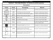
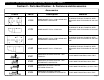
Series 8700 / 8800 Unitized Curtain Wall Assembly Instructions - Volume 1 Section 2 - Parts Identification : G. Extrusions Extrusions Profile EFCO 2009 Part # Description Tooling/Cut Length Formula 17B4 OPTIONAL CAPTURED GLAZING RETAINER CUT TO LENGTH - HORIZ. UNIT DIM. MINUS .250 - USE WITH 17A4 AND 17A5 AT STACK HEAD 17B5 CAPTURED STACK SILL GLAZING ADAPTER CUT TO LENGTH - HORIZ. UNIT DIM. MINUS .250 17K1 CAPTURED GLAZING RETAINER AT STACK HEAD CUT TO LENGTH - HORIZ. UNIT DIM. MINUS .
Series 8700 / 8800 Unitized Curtain Wall Assembly Instructions - Volume 1 Section 2 - Parts Identification : G. Extrusions Extrusions Profile Part # Description Tooling/Cut Length Formula 17H6 SSG INTERMEDIATE HORIZONTAL GLAZING ADAPTER U17H6-001, U17H6-002, U17H6-003 17C0 OPTIONAL SSG INTERMEDIATE HORIZ. GLAZING ADAPTER U17C0-001 17A9 SSG JAMB MULLION COVER CUT TO LENGTH - VERTICAL UNIT DIM. MINUS 1.500 90° O.S. CORNER MULLION ANCHOR REFERENCE FM07 PART DRAWING 90° I.S.
Series 8700 / 8800 Unitized Curtain Wall Assembly Instructions - Volume 1 Section 2 - Parts Identification : G. Extrusions Extrusions Profile Part # Tooling/Cut Length Formula 17E7 CAPTURED 90° I.S. CORNER MULLION GLAZING ADAPTER CUT TO LENGTH - VERTICAL UNIT DIM. MINUS 3.688 17J9 CAPTURED 90° I.S. CORNER EXTERIOR GLAZING BEAD CUT TO LENGTH - VERTICAL D.L.O. MINUS .063 17E9 CAPTURED 90° I.S. CORNER INTERIOR GLAZING BEAD U17E9-001 17F6 SSG 90° O.S.
Series 8700 / 8800 Unitized Curtain Wall Assembly Instructions - Volume 1 Section 2 - Parts Identification : H.
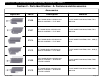
Series 8700 / 8800 Unitized Curtain Wall Assembly Instructions - Volume 1 Section 2 - Parts Identification : H. Concealed Vent Extrusions Concealed Vent Extrusions Profile EFCO 2009 Part # Description Tooling/Cut Length Formula 17L5 CONCEALED VENT JAMB ADAPTER U17L5-001, U17L5-002 17L4 POCKET FILLER FOR CAPTURED CONCEALED VENT REFER TO SHOP DRAWINGS 17L1 CAPTURED SILL SASH COVER AT STACK SILL CUT TO LENGTH - HORIZONTAL D.L.O. MINUS .
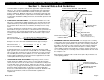
Series 8700 / 8800 Unitized Curtain Wall Assembly Instructions - Volume 1 Section 3 - Unit Frame Assembly : A. Mullion Subassembly 1. Slide WC21 gasket into the male vertical mullion. Exercise care to avoid stretching the gasket. The gasket should be crowded when inserted into the gasket reglet and overhang each end of the mullion at least 1”. 2.
Series 8700 / 8800 Unitized Curtain Wall Assembly Instructions - Volume 1 Section 3 - Unit Frame Assembly : A. Mullion Subassembly 3. Identify the appropriate frame gasket for the intended application (refer to the parts list cross reference on the following page for more information). 4. Clean the mullion surfaces that will contact the frame pads. Using an approved solvent or cleaner, clean the surfaces of all oils and other contaminants. 5.
Series 8700 / 8800 Unitized Curtain Wall Assembly Instructions - Volume 1 Section 3 - Unit Frame Assembly : A. Mullion Subassembly 8. Frame pads are required at each mullion intersection. See Table 1. 9. Note: Some pads have right hand and left hand versions and will be provided on a roll, side by side. Tear the pads at the serrations and use the handed pads as required. Apply frame pad to the mullion.
Series 8700 / 8800 Unitized Curtain Wall Assembly Instructions - Volume 1 Section 3 - Unit Frame Assembly : A. Mullion Subassembly 10. 11. 12. 13. 14. Apply the “Z” clip caulk backer to the bottom end of all vertical mullions. Thoroughly clean the surfaces of the “Z” clip and mullion that will contact sealant. Apply a bead of sealant to the mullion as shown in Figure 11. Apply a bed of sealant to the “Z” clip on the face of the 1 1/2” long leg as shown in Figure 12.
Series 8700 / 8800 Unitized Curtain Wall Assembly Instructions - Volume 1 Section 3 - Unit Frame Assembly : A. Mullion Subassembly 15. Tool the sealant into the joint between the “Z” clip and the mullion. 16. Remove excess sealant if required.
Series 8700 / 8800 Unitized Curtain Wall Assembly Instructions - Volume 1 Section 3 - Unit Frame Assembly : A. Mullion Subassembly 17. Apply the FM18 jamb mullion spacers to jamb mullions only. Spacers will be located at horizontals as shown in Figure 16 and 18, and on each end of the jamb mullion. FM18 jamb spacers at horizontal locations must be applied before frame assembly and after the frame pads have been applied. (See Figures 16 and 18). 18.
Series 8700 / 8800 Unitized Curtain Wall Assembly Instructions - Volume 1 Section 3 - Unit Frame Assembly : A. Mullion Subassembly 19. Assemble the anchor kits by screwing in the M170 set screw into the bottom of the FM11 mullion anchors until the set screw is flush with the bottom of the anchor. (Left and Right Hand Assemblies Required.) 20. Slide the FM05 or FM06 hook anchor into the FM11 mullion anchor as shown in Figure 20 and 21. See END VIEW on page 33 for part orientation. 21.
Series 8700 / 8800 Unitized Curtain Wall Assembly Instructions - Volume 1 Section 3 - Unit Frame Assembly : A. Mullion Subassembly 22. Apply the mullion anchor assemblies and the FM17 bolt retainers to the unit vertical mullions. Insert (3) 3/8”-16 bolts (M174) through the bolt retainer and mullion. 23. Use either a right or left hand anchor assembly to orient the top of the anchor and mullion as shown in Figure 23 and the END VIEW, and insert the anchor over the bolts. 24.
Series 8700 / 8800 Unitized Curtain Wall Assembly Instructions - Volume 1 Section 3 - B. Unit Frame Assembly 1. Assemble the framing facing upward (glazing side up). Use saw horses or assembly tables during assembly. Provisions to protect the finished surfaces of the material must be employed on the table or saw horses. 2. Check to ensure the frame gaskets are intact and properly applied. 3.
Series 8700 / 8800 Unitized Curtain Wall Assembly Instructions - Volume 1 Section 3 - B. Unit Frame Assembly 4. Attach the mullion splice bars (FM15, FM16) to the top of the unit jambs with IHP8 (1/4”-20 x 1” HX-MS 18-8) and M173 1/4”-20 nylon insert stop nut as shown in below. The splice bar has an integral bolt track to back the bolt during tightening for ease of installation. 5. Torque the bolt tight, but do not over tighten.