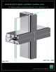
Series 8700 / 8800 Unitized Curtain Wall Assembly Instructions - Volume 2 EFCO 2012 PART NO.
Table of Contents Volume 1 of 6 1. General Notes and Guidelines 2. Parts Identification 3. Frame Assembly Volume 2 of 6 SECTION PAGE 4. Unit Glazing Preparation : SSG and Captured…………......................................... 6 - 7 5. SSG Unit Glazing A. Temporary Glazing Locators…………………………...................................... 8 B. Setting and Caulking Glazing …………………………………………………… 9 - 10 C. Adapter Installation………………….…………………………………………….. 11 - 15 D.
Series 8700 / 8800 Unitized Curtain Wall Assembly Instructions - Volume 2 EFCO 2009 Series 8700 / 8800 Unitized Curtain Wall Assembly Instructions - Volume 2 Table of Contents Volume 3 of 6 7. Outside 90° Corner Frame Assembly 8. Inside 90° Corner Frame Assembly 9. Outside 90° Corner Unit Glazing Preparation : SSG and Captured 10. Inside 90° Corner Unit Glazing Preparation : SSG and Captured Volume 4 of 6 11. Outside 90° Corner SSG Unit Glazing 12. Inside 90° Corner SSG Unit Glazing 13.
Series 8700 / 8800 Unitized Curtain Wall Assembly Instructions - Volume 2 EFCO 2009 Series 8700 / 8800 Unitized Curtain Wall Assembly Instructions - Volume 2 Table of Contents Volume 5 of 6 15. General Notes and Guidelines 16. Size Limitations 17. Standard Hardware Identification 18. Frame Assembly - Vent at Fixed Horizontal 19. Frame Assembly - Vent at Stack Sill 20. Unit Glazing Preparation - Vent at Fixed Horizontal 21. Unit Glazing Preparation - Vent at Stack Sill 22.
Series 8700 / 8800 Unitized Curtain Wall Assembly Instructions - Volume 2 Series 8700 / 8800 Unitized Curtain Assembly Instructions - Volume 2 Table Wall of Contents Volume 6 of 6 33. Shadow Box Assembly 34. Shadow Box Installation 35. Shadow Box Insulation Installation 36. Back Panel Installation 37. Back Panel Insulation Installation 38. Final Cleaning Minimizing Condensation Note: Please reference EFCO's "Understanding Condensation" brochure which can be obtained through your EFCO representative.
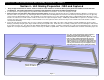
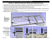
Series 8700 / 8800 Unitized Curtain Wall Assembly Instructions - Volume 2 Section 4 - Unit Glazing Preparation : SSG and Captured 1. Using an approved solvent or cleaner, clean the surfaces of the mullions to receive the WC18 spacer gasket and sealant of all oils and other contaminants. The sealant manufacturer’s preparation and application instructions should be followed exactly. 2. If sealant primer is required, apply it per the primer/sealant manufacturer’s instructions. See the note in Figure 1 below.
Series 8700 / 8800 Unitized Curtain Wall Assembly Instructions - Volume 2 Section 4 - Unit Glazing Preparation : SSG and Captured 5. Apply the WC18 spacer gasket to the mullions as shown below and on page 6. The gasket will run through vertically, and butt together at the corners (see Figure 4). “Crowd” in extra gasket, (approximately 10% extra) where it runs between the vertical gaskets to ensure a snug butt joint at the corners.
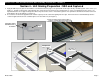
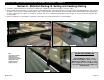
Series 8700 / 8800 Unitized Curtain Wall Assembly Instructions - Volume 2 Section 5 - SSG Unit Glazing : A. Temporary Glazing Locators 1. In order to properly locate the glazing, temporary adapters must be used at the bottom edge of the glazing. Apply two temporary glazing locators (KV01, KV02) at approximate quarter points at the sill and intermediate horizontal locations as shown in Figures 5, 6, and 7. 2.
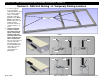
Series 8700 / 8800 Unitized Curtain Wall Assembly Instructions - Volume 2 Section 5 - SSG Unit Glazing: B. Setting and Caulking Glazing 3. Set the glazing on the silicone spacer gaskets positioned as shown below. The edge of the glazing is flush with the edge of the vertical mullion. Refer to Figure 9 below. Ensure the glazing is pressed firmly onto the setting blocks of the temporary retainers as shown in Figures 10 and 11. 4. Align the glazing as shown and noted.
Series 8700 / 8800 Unitized Curtain Wall Assembly Instructions - Volume 2 Section 5 - SSG Unit Glazing: B. Setting and Caulking Glazing 9. Follow the sealant manufacturer’s instructions for application equipment preparation and quality control procedures. 10. Apply sealant and tool the frames as required per the sealant manufacturer’s application instructions in the Structural Sealant Glazing Manual. Care should be taken to insure that the sealant void at the glass edge is completely filled.
Series 8700 / 8800 Unitized Curtain Wall Assembly Instructions - Volume 2 Section 5 - SSG Unit Glazing: C. Adapter Installation 1. After sealant has cured, cut L142 to length with vinyl cutters. Apply the thermal isolator L142 into the verticals and horizontals. L142 is supplied in 10’-0” lengths. L142 may be used in several pieces to accommodate the required length. By butting multiple pieces together, waste will be avoided and the desired length can be obtained. 2.
Series 8700 / 8800 Unitized Curtain Wall Assembly Instructions - Volume 2 Section 5 - SSG Unit Glazing: C. Adapter Installation 4. Apply 17B7 SSG glazing adapter to the stack sill. Final adjustment of the 17B7 will be made after the vertical glazing adapters are applied. 5. Slide the WC17 horizontal stack joint rain screen gasket into position as shown in Figures 20, 21, and 22. WC17 runs the same length as 17B7 and is applied flush with each end of 17B7. 6.
Series 8700 / 8800 Unitized Curtain Wall Assembly Instructions - Volume 2 Section 5 - SSG Unit Glazing: C. Adapter Installation 7. Clean the sealant contact surfaces of the mullion with an approved solvent or cleaner and apply a heavy bead of sealant to the tops of the vertical mullions as shown in Figure 23. 8. Clean the sealant contact surfaces of the gutter with an approved solvent or cleaner.
Series 8700 / 8800 Unitized Curtain Wall Assembly Instructions - Volume 2 Section 5 - SSG Unit Glazing: C. Adapter Installation 10. Slide WC20 bulb gasket into 17A6 SSG vertical fin bar. Exercise care to avoid stretching the gasket during installation. Let the bulb gasket run approximately 1/4” longer than 17A6. The bulb gasket must be installed prior to applying 17A6. 11. Crimp the bulb in place to prevent slippage during unit installation. Crimp at each end of the adapter, and 24” on center. 12.
Series 8700 / 8800 Unitized Curtain Wall Assembly Instructions - Volume 2 Section 5 - SSG Unit Glazing: C. Adapter Installation 14. Using an approved solvent or cleaner, clean the surfaces of the mullions at the intersection of the intermediate horizontal and vertical. 15. Apply a heavy bead of sealant at the intersection of the intermediate horizontal and vertical (See Figure 32).
Series 8700 / 8800 Unitized Curtain Wall Assembly Instructions - Volume 2 Section 5 - SSG Unit Glazing: D. Weather Seal Application 1. Using an approved solvent or cleaner, clean the sealant contact surfaces of the glazing and adapters of all oils and other contaminants. 2. If sealant primer is required, apply it per the primer/sealant manufacturer’s instructions. 3. Insert 3/8” diameter backer rod between the glazing and adapters around all four corners of each lite of glazing.
Series 8700 / 8800 Unitized Curtain Wall Assembly Instructions - Volume 2 Section 5 - SSG Unit Glazing: D. Weather Seal Application 6. Ensure the sealant continuity joints between the adapters are properly filled with sealant and tooled smoothly for best aesthetics. Refer to Figures 35, 36, and 37 on page 16 for detailed views of the weather seals and sealant continuity joints. 7. Allow units to sit undisturbed until the sealant is cured and per the sealant manufacturer’s recommendations. 8.
Series 8700 / 8800 Unitized Curtain Wall Assembly Instructions - Volume 2 Section 5 - SSG Unit Glazing: E. Jamb Mullion Installation 1. Clean the sealant contact surfaces on the underside of the gutter (Figure 40) and the top of the jamb (Figure 41) using an approved solvent or cleaner. Apply a heavy bed of sealant to the underside of the gutter and onto the mullion stack leg of the assembled mullion as shown in Figure 40. 2. Apply a heavy bead of sealant to the jamb as shown in Figure 41. 3.
Series 8700 / 8800 Unitized Curtain Wall Assembly Instructions - Volume 2 Section 5 - SSG Unit Glazing: E. Jamb Mullion Installation 5. Clean the end dam of all oils and contaminants and apply a bed of sealant to the jamb corresponding to where the end dam will be applied. 6. Before the sealant begins to cure or skin over from steps 1 and 2, apply the gutter end dam flush with the underside and notched face of the gutter with (2) STT6 screws. 7.
Series 8700 / 8800 Unitized Curtain Wall Assembly Instructions - Volume 2 Section 6 - Captured Unit Glazing : A. Temporary Glazing Locators 1. In order to properly locate the glazing, temporary adapters must be used at the bottom edge of the glazing. Apply two temporary glazing locators KV03 AND KV04 at approximate quarter points of the sill and intermediate horizontal locations as shown in Figures 50, 51, and 52. 2.
Series 8700 / 8800 Unitized Curtain Wall Assembly Instructions - Volume 2 Section 6 - Captured Unit Glazing : B. Setting and Caulking Glazing 3. Set the glazing on the silicone spacer gaskets positioned as shown below. The edge of the glazing is flush with the edge of the vertical mullion. Refer to Figure 54 below. Ensure the glazing is pressed firmly onto the setting blocks of the temporary retainers as shown in Figures 55 and 56. 4. Align the glazing as shown and noted.
Series 8700 / 8800 Unitized Curtain Wall Assembly Instructions - Volume 2 Section 6 - Captured Unit Glazing : B. Setting and Caulking Glazing 9. Follow the sealant manufacturer’s instructions for application equipment preparation and quality control procedures. 10. Apply sealant and tool the frames as required per the sealant manufacturer’s application instructions in the Structural Sealant Glazing Manual. Care should be taken to insure that the sealant void at the glass edge is completely filled.
Series 8700 / 8800 Unitized Curtain Wall Assembly Instructions - Volume 2 Section 6 - Captured Unit Glazing: C. Adapter and Cover Installation 1. Cut L142 to length with vinyl cutters. Apply the thermal isolator L142 into the verticals and horizontals. L142 is supplied in 10’-0” lengths. L142 may be used in several pieces to accommodate the required length. By butting multiple pieces together, waste will be avoided and the desired length can be obtained. 2.
Series 8700 / 8800 Unitized Curtain Wall Assembly Instructions - Volume 2 Section 6 - Captured Unit Glazing: C. Adapter and Cover Installation 4. Apply 17B5 Captured glazing adapter to the stack sill. Final adjustment of the 17B5 will be made after the vertical glazing adapters are applied. 5. Slide the WC17 horizontal stack joint rain screen gasket into position as shown in Figures 65, 66, and 67. WC17 runs the same length as 17B5 and is applied flush with each end of 17B5. 6.
Series 8700 / 8800 Unitized Curtain Wall Assembly Instructions - Volume 2 Section 6 - Captured Unit Glazing: C. Adapter and Cover Installation 7. Clean the sealant contact surfaces of the mullion with an approved solvent or cleaner and apply a heavy bead of sealant to the tops of the vertical mullions as shown in Figure 68. 8. Clean the sealant contact surfaces of the gutter with an approved solvent or cleaner.
Series 8700 / 8800 Unitized Curtain Wall Assembly Instructions - Volume 2 Section 6 - Captured Unit Glazing: C. Adapter and Cover Installation 10. Insert 17K1 glazing retainer into 17B5 and roll into position (See Figure 73). Insert 17K0 glazing retainer into 17B1 and roll into position (See Figure 74). The glazing retainers will be flush with the ends of the adapters. 11. Drive in WC22 wedge gasket between 17K0, 17K1 and the glazing infill as shown in Figures 75 and 76.
Series 8700 / 8800 Unitized Curtain Wall Assembly Instructions - Volume 2 Section 6 - Captured Unit Glazing: C. Adapter and Cover Installation 12. Slide WC20 bulb gasket into 17A2 captured vertical fin bar. Exercise care to avoid stretching the gasket during installation. Let the bulb gasket extend approximately 1 1/2” longer than 17A2 on each end. The bulb gasket should be installed prior to applying 17A2. 13. Crimp the bulb in place to prevent slippage during unit installation.
Series 8700 / 8800 Unitized Curtain Wall Assembly Instructions - Volume 2 Section 6 - Captured Unit Glazing: C. Adapter and Cover Installation 16. Using an approved solvent or cleaner, clean the surfaces of the mullions at the intersection of the intermediate horizontal and vertical. 17. Apply a heavy bead of sealant at the intersection of the intermediate horizontal and vertical (See Figure 83).
Series 8700 / 8800 Unitized Curtain Wall Assembly Instructions - Volume 2 Section 6 - Captured Unit Glazing: C. Adapter and Cover Installation 23. Insert 17B8 cover onto 17B9 captured glazing adapter and rotate into place as shown in Figures 86 and 87. 24. Cut the WC22 gaskets approximately 2” longer than the D.L.O. dimension. 25. Drive in WC22 wedge gaskets starting with the gasket on the setting block side of the glazing pocket. The gaskets should be applied starting in the center of the D.L.O.
Series 8700 / 8800 Unitized Curtain Wall Assembly Instructions - Volume 2 Section 6 - Captured Unit Glazing: C. Adapter and Cover Installation 26. Insert 17A3 cover into 17A2 captured glazing adapter at each unit jamb and rotate into place as shown in Figures 89 and 90. 27. Cut the WC22 gaskets approximately 2” longer than the D.L.O. dimension. 28. Drive in WC22 wedge gaskets as shown in Figure 90. The gaskets should be applied starting in the center of the D.L.O.
Series 8700 / 8800 Unitized Curtain Wall Assembly Instructions - Volume 2 Section 6 - Captured Unit Glazing: D. Joint Plug Installation 1. HNC4 joint plugs will be required at the head and sill of the assembled unit frame. Using an approved solvent or cleaner, clean the surfaces of the mullions where the joint plug will be applied.
Series 8700 / 8800 Unitized Curtain Wall Assembly Instructions - Volume 2 Section 6 - Captured Unit Glazing: D. Joint Plug Installation 2. 3. 4. 5. 6. Examine the joint plugs, and if contamination has occurred, clean them if necessary. Apply a heavy bead of sealant around the joint plug on the sealant contact surfaces (See Figure 94). Insert the joint plug into the opening between the adapter and covers at the head and sill of the unit. Apply beads of sealant over the joint plug as shown in Figure 95.
Series 8700 / 8800 Unitized Curtain Wall Assembly Instructions - Volume 2 Section 6 - Captured Unit Glazing: E. Jamb Mullion Installation 1. Clean the sealant contact surfaces on the underside of the gutter (Figure 98) and the top of the jamb (Figure 99) using an approved solvent or cleaner. Apply a heavy bed of sealant to the underside of the gutter and onto the mullion stack leg of the assembled mullion as shown in Figure 98. 2. Apply a heavy bead of sealant to the jamb as shown in Figure 99. 3.
Series 8700 / 8800 Unitized Curtain Wall Assembly Instructions - Volume 2 Section 6 - Captured Unit Glazing: E. Jamb Mullion Installation 5. Clean the end dam of all oils and contaminants and apply a bed of sealant to the jamb corresponding to where the end dam will be applied. 6. Before the sealant begins to cure or skin over from steps 1 and 2, apply the gutter end dam flush with the underside and notched face of the gutter with (2) STT6 screws. 7.