Concealed Vent Assembly Instructions Volume 5 of 6 - Sections 15 - 32 July 2011 PART NO.
Series 8700 / 8800 Unitized Curtain Wall Assembly Instructions - Volume 5 EFCO 2009 Series 8700 / 8800 Unitized Curtain Wall Assembly Instructions - Volume 5 Table of Contents Volume 1 of 6 1. General Notes and Guidelines 2. Parts Identification 3. Frame Assembly Volume 2 of 6 4. Unit Glazing Preparation : SSG and Captured 5. SSG Unit Glazing 6. Captured Unit Glazing Volume 3 of 6 7. Outside 90° Corner Frame Assembly 8. Inside 90° Corner Frame Assembly 9.
Table of Contents Volume 5 of 6 SECTION PAGE 15. General Notes and Guidelines……..…………………………………………………… 6 16. Size Limitations……………………………………………………………………………. 7 17. Standard Hardware Identification………………………………………………………. 8 - 9 18. Frame Assembly - Vent at Fixed Horizontal………………………………………….. 10 - 13 19. Frame Assembly - Vent at Stack Sill……….………………………………………….. 14 - 17 20. Unit Glazing Preparation - Vent at Fixed Horizontal………………………………… 18 - 19 21. Unit Glazing Preparation - Vent at Stack Sill……….
Series 8700 / 8800 Unitized Curtain Wall Assembly Instructions - Volume 5 Table Wall of Contents Series 8700 / 8800 Unitized Curtain Assembly Instructions - Volume 5 Volume 5 of 6 SECTION PAGE 25. Captured Vent Unit Glazing at Stack Sill A. Temporary Glazing Locators…………………………...................................... 45 B. Setting and Caulking Glazing …………………………………………………… 46 - 47 C. Adapter and Cover Installation………………………………………………….. 48 - 52 D. Joint Plug Installation……………………………………………………………...
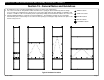
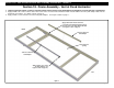
Series 8700 / 8800 Unitized Curtain Wall Assembly Instructions - Volume 5 Section 15 - General Notes and Guidelines 1. Below illustrates the recommended hardware locations for various unit configurations. 2. The exact lock locations and quantities will be determined on a job by job basis and will vary with the design pressure and vent configuration for a given project. Refer to the final approved shop drawings for quantities and locations.
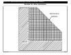
Series 8700 / 8800 Unitized Curtain Wall Assembly Instructions - Volume 5 Section 16 - Size Limitations 84” 80” 75” Maximum Rectangular Vent Size 84” x 36” or 36” x 84” 70” Maximum Square Vent Size 60” x 60” 65” 60” 55” 50” 45” 40” 35” 30” 25” 20” 20” 25” 30” 35” 40” 45” 50” 55” 60” 65” 70” 75” 80” 84” Minimum Vent Size 20” x 20” EFCO 2009 Page 6
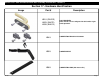
Series 8700 / 8800 Unitized Curtain Wall Assembly Instructions - Volume 5 Section 17 - Hardware Identification Image Part # H01U (SILVER) H02U (WHITE) H03U (BLACK) EFCO 2009 Description LOCK HANDLES Note: Handle can be configured for left hand or right hand operation.
Series 8700 / 8800 Unitized Curtain Wall Assembly Instructions - Volume 5 Section 17 - Hardware Identification Image EFCO 2009 Part # Description H07U ADJUSTABLE SNUBBER H08U ADJUSTABLE LOCKING POINT (KEEPER AND PAWL) L20A (20”) L24A (24”) L28A (28”) 4-BAR PROJECTED ARM LA03 (5”) LA04 (8”) ALLEN KEYED RELEASE LIMIT ARM (USES “HM70” SECURITY ALLEN WRENCH AS KEY) Page 8
Series 8700 / 8800 Unitized Curtain Wall Assembly Instructions - Volume 5 Section 18 - Frame Assembly - Vent at Fixed Horizontal 1. Assembly the concealed vent unit frame. Refer to Volume 1 and Volume 2 of the S-8000 Unitized Curtain Wall Assembly Instructions for assembly details as noted below. Refer to Volume 1, Page 35 for Mullion Splice Bar application. Refer to Volume 1, Page 26 for mullion gasket installation.
Series 8700 / 8800 Unitized Curtain Wall Assembly Instructions - Volume 5 Section 18 - Frame Assembly - Vent at Fixed Horizontal 2. Using an approved solvent or cleaner, clean the sealant contact surfaces of the jamb adapters and mullions of all oils and other contaminants. 3. Apply sealant to the contact surfaces at the intersection of the concealed vent horizontals and the vertical mullions where the jamb adapter abuts into the horizontals (4 locations). See Figure 3 and 4 on page 11. 4.
Series 8700 / 8800 Unitized Curtain Wall Assembly Instructions - Volume 5 Section 18 - Frame Assembly - Vent at Fixed Horizontal Apply sealant to each end of the jamb adapters. Apply sealant at the intersection of the vent horizontals and the verticals where the ends of the jamb adapter will abut. 17K2 Concealed Vent Horizontal Figure 3 Figure 5 17K2 Concealed Vent Horizontal Apply sealant at the intersection of the vent horizontals and the verticals where the ends of the jamb adapter will abut.
Series 8700 / 8800 Unitized Curtain Wall Assembly Instructions - Volume 5 Section 18 - Frame Assembly - Vent at Fixed Horizontal 5. Set the jamb adapter into the notched areas of the concealed vent horizontals where the sealant was applied. Ensure the adapter is flush with the horizontal as shown in Figure 9. 6. Match drill the vertical mullion through the holes in the jamb adapters and attach the adapters with SPZ0 screws. Cap seal the screws where they penetrate the mullion. See Figure 8.
Series 8700 / 8800 Unitized Curtain Wall Assembly Instructions - Volume 5 Section 19 - Frame Assembly - Vent at Stack Sill 1. Assembly the concealed vent unit frame. Refer to Volume 1 and Volume 2 of the S-8000 Unitized Curtain Wall Assembly Instructions for assembly details as noted below. Refer to Volume 1, Page 35 for Mullion Splice Bar application. Refer to Volume 1, Page 26 for mullion gasket installation. Stack Head H11B Frame Pad Refer to Volume 1, Page 27 - 28 for frame pad application.
Series 8700 / 8800 Unitized Curtain Wall Assembly Instructions - Volume 5 Section 19 - Frame Assembly - Vent at Stack Sill 2. Using an approved solvent or cleaner, clean the sealant contact surfaces of the jamb adapters and mullions of all oils and other contaminants. 3. Apply sealant to the contact surfaces at the intersection of the concealed vent horizontals and the vertical mullions where the jamb adapter abuts into the horizontals (4 locations). See Figures 12 and 13 on page 15. 4.
Series 8700 / 8800 Unitized Curtain Wall Assembly Instructions - Volume 5 Section 19 - Frame Assembly - Vent at Stack Sill Apply sealant to each end of the jamb adapters. Apply sealant at the intersection of the vent horizontals and the verticals where the ends of the jamb adapter will abut. 17K2 Concealed Vent Horizontal Figure 12 17K2 Concealed Vent Stack Sill Apply sealant to each end of the jamb adapters.
Series 8700 / 8800 Unitized Curtain Wall Assembly Instructions - Volume 5 Section 19 - Frame Assembly - Vent at Stack Sill 5. Set the jamb adapter into the notched areas of the concealed vent horizontals where the sealant was applied. Ensure the adapter is flush with the horizontal as shown in Figure 18. 6. Match drill the vertical mullion through the holes in the jamb adapters and attach the adapters with SPZ0 screws. Cap seal the screws where they penetrate the mullion. See Figure 17.
Series 8700 / 8800 Unitized Curtain Wall Assembly Instructions - Volume 5 Section 20 - Unit Glazing Preparation - Vent at Fixed Horizontal 1. Using an approved solvent or cleaner, clean the surfaces of the mullions to receive the WC18 spacer gasket and sealant of all oils and other contaminants. The sealant manufacturer’s preparation and application instructions should be followed exactly. 2. If sealant primer is required, apply it per the primer/sealant manufacturer’s instructions.
Series 8700 / 8800 Unitized Curtain Wall Assembly Instructions - Volume 5 Section 20 - Unit Glazing Preparation - Vent at Fixed Horizontal 4. Apply the WC18 spacer gasket to the mullions as shown below and on the previous page. The gaskets will run through as shown below. Butt the gaskets together at the corners (see Figure 22). “Crowd” in extra gasket, (approximately 4% to 5% extra) where it runs between the gaskets to ensure a snug butt joint at the corners.
Series 8700 / 8800 Unitized Curtain Wall Assembly Instructions - Volume 5 Section 21 - Unit Glazing Preparation - Vent at Stack Sill 1. Using an approved solvent or cleaner, clean the surfaces of the mullions to receive the WC18 spacer gasket and sealant of all oils and other contaminants. The sealant manufacturer’s preparation and application instructions should be followed exactly. 2. If sealant primer is required, apply it per the primer/sealant manufacturer’s instructions.
Series 8700 / 8800 Unitized Curtain Wall Assembly Instructions - Volume 5 Section 21 - Unit Glazing Preparation - Vent at Stack Sill 4. Apply the WC18 spacer gasket to the mullions as shown below and on the previous page. The gaskets will run through as shown below. Butt the gaskets together at the corners (see Figure 26). “Crowd” in extra gasket, (approximately 4% to 5% extra) where it runs between the gaskets to ensure a snug butt joint at the corners.
Series 8700 / 8800 Unitized Curtain Wall Assembly Instructions - Volume 5 Section 22 - SSG Vent Unit Glazing at Fixed Horizontal : A. Temporary Glazing Locators 1. Apply two temporary glazing locators (KV01 and KV02) with isolators and setting blocks at approximate quarter points at the sill and intermediate horizontal locations. 2. Refer to Volume 2, page 8 and 9 of the S-8000 Unitized Curtain Wall Assembly Instructions for assembly details and notes.
Series 8700 / 8800 Unitized Curtain Wall Assembly Instructions - Volume 5 Section 22 - SSG Vent Unit Glazing at Fixed Horizontal : B. Setting and Caulking Glazing 1. Set the glazing on the silicone spacer gaskets making sure glazing is pressed firmly onto the setting blocks of the temporary retainers. 2. Refer to Volume 2, pages 9 and 10 of the S-8000 Unitized Curtain Wall Assembly Instructions for assembly details and notes.
Series 8700 / 8800 Unitized Curtain Wall Assembly Instructions - Volume 5 Section 22 - SSG Vent Unit Glazing at Fixed Horizontal : B. Setting and Caulking Glazing 3. Remove the temporary glazing retainers. 4. Apply structural silicone sealant into the voids between the glass and mullions per the sealant manufacturer’s application instructions. Frames should not be moved until the sealant has cured and per the sealant manufacturer’s recommendations. 5.
Series 8700 / 8800 Unitized Curtain Wall Assembly Instructions - Volume 5 Section 22 - SSG Vent Unit Glazing at Fixed Horizontal : C. Adapter Installation 1. Apply L142 thermal isolator clip to the verticals and horizontals. Apply WC16 to the head member. Refer to Volume 2, page 11 of the S-8000 Unitized Curtain Wall Assembly Instructions for more information. 2. Apply the 17B7 SSG glazing adapter to the stack sill. Slide the WC17 horizontal stack joint rain screen gasket into position.
Series 8700 / 8800 Unitized Curtain Wall Assembly Instructions - Volume 5 Section 22 - SSG Vent Unit Glazing at Fixed Horizontal : C. Adapter Installation 6. Slide the WS00 vent surround gasket into the 17A6 adapters that will be applied to the intermediate horizontals above and below the concealed vent opening. Cut the WS00 gasket about 1/4” longer than the 17A6 adapter that will be applied at the head of the vent opening.
Series 8700 / 8800 Unitized Curtain Wall Assembly Instructions - Volume 5 Section 22 - SSG Vent Unit Glazing at Fixed Horizontal : C. Adapter Installation WS00 gasket is cut 3” short of the adapter at the sill horizontal and is centered in the opening. WS00 gasket butts into 17A6 at the head horizontal on each end. VENT HEAD VENT SILL WA07 butts into adapter. WA07 runs under WS00 and butts into adapter. Figure 32 Figure 33 Insert WA07 vent bulb gasket into each jamb. Insert HS32 setting blocks.
Series 8700 / 8800 Unitized Curtain Wall Assembly Instructions - Volume 5 Section 22 - SSG Vent Unit Glazing at Fixed Horizontal : D. Weather Seal Application 1. 2. 3. 4. 5. 6. 7. Using an approved solvent or cleaner, clean the sealant contact surfaces of the glazing and adapters of all oils and other contaminants. If sealant primer is required, apply it per the primer/sealant manufacturer’s instructions.
Series 8700 / 8800 Unitized Curtain Wall Assembly Instructions - Volume 5 Section 23 - SSG Vent Unit Glazing at Stack Sill : A. Temporary Glazing Locators 1. Apply two temporary glazing locators (KV02) with isolators and setting blocks at approximate quarter points at the intermediate horizontal locations. 2. Refer to Volume 2, page 8 of the S-8000 Unitized Curtain Wall Assembly Instructions for assembly details and notes.
Series 8700 / 8800 Unitized Curtain Wall Assembly Instructions - Volume 5 Section 23 - SSG Vent Unit Glazing at Stack Sill : B. Setting and Caulking Glazing 1. Set the glazing on the silicone spacer gaskets making sure glazing is pressed firmly onto the setting blocks of the temporary retainers. 2. Refer to Volume 2, pages 9 and 10 of the S-8000 Unitized Curtain Wall Assembly Instructions for assembly details and notes.
Series 8700 / 8800 Unitized Curtain Wall Assembly Instructions - Volume 5 Section 23 - SSG Vent Unit Glazing at Stack Sill : B. Setting and Caulking Glazing 3. Remove the temporary glazing retainers. 4. Apply structural silicone sealant into the voids between the glass and mullions per the sealant manufacturer’s application instructions. Frames should not be moved until the sealant has cured and per the sealant manufacturer’s recommendations. 5.
Series 8700 / 8800 Unitized Curtain Wall Assembly Instructions - Volume 5 Section 23 - SSG Vent Unit Glazing at Stack Sill : C. Adapter Installation 1. Apply L142 thermal isolator clip to the verticals and horizontals. Apply WC16 to the head member. Refer to Volume 2, page 11 of the S-8000 Unitized Curtain Wall Assembly Instructions for more information. 2. Slide the WC17 horizontal stack joint rain screen gasket into the concealed vent stack sill.
Series 8700 / 8800 Unitized Curtain Wall Assembly Instructions - Volume 5 Section 23 - SSG Vent Unit Glazing at Stack Sill : C. Adapter Installation 7. Drill tap sized holes (.113 diameter or #33 drill) in the face of the vertical assemblies, 1” from the sill end of the vent opening, and 18” on center to the top of the vent opening. See figure 46 below. Drill the holes in the groove formed where the adapter meets the mullion.
Series 8700 / 8800 Unitized Curtain Wall Assembly Instructions - Volume 5 Section 23 - SSG Vent Unit Glazing at Stack Sill : C. Adapter Installation 9. Slide the WS00 vent surround gasket into the 17A6 adapters that will be applied to the intermediate horizontals at the head of the concealed vent opening. Cut the WS00 gasket about 1/4” longer than the 17A6 adapter that will be applied at the head of the vent opening. See Figures 49 through 52 on page 34. 10.
Series 8700 / 8800 Unitized Curtain Wall Assembly Instructions - Volume 5 Section 23 - SSG Vent Unit Glazing at Stack Sill : C. Adapter Installation WA07 butts into sill. WS00 gasket butts into 17A6 at the head horizontal on each end. VENT HEAD WA07 runs under WS00 and butts into adapter. VENT SILL Figure 49 Figure 50 Insert WA07 vent bulb gasket into each jamb. Insert HS32 setting blocks. WA07 butts into sill. WA07 butts into adapter.
Series 8700 / 8800 Unitized Curtain Wall Assembly Instructions - Volume 5 Section 23 - SSG Vent Unit Glazing at Stack Sill : D. Weather Seal Application 1. Using an approved solvent or cleaner, clean the sealant contact surfaces of the glazing and adapters of all oils and other contaminants. 2. If sealant primer is required, apply it per the primer/sealant manufacturer’s instructions. 3. Insert 3/8” diameter backer rod between the glazing and adapters around all four corners of each lite of glazing.
Series 8700 / 8800 Unitized Curtain Wall Assembly Instructions - Volume 5 Section 24 - Captured Vent Unit Glazing at Fixed Horizontal : A. Temporary Glazing Locators 1. Apply two temporary glazing locators (KV03 and KV04) with isolators and setting blocks at approximate quarter points at the sill and intermediate horizontal locations. 2. Refer to Volume 2, page 20 and 21 of the S-8000 Unitized Curtain Wall Assembly Instructions for assembly details and notes.
Series 8700 / 8800 Unitized Curtain Wall Assembly Instructions - Volume 5 Section 24 - Captured Vent Unit Glazing at Fixed Horizontal : B. Setting and Caulking Glazing 1. Set the glazing on the silicone spacer gaskets making sure glazing is pressed firmly onto the setting blocks of the temporary retainers. 2. Refer to Volume 2, pages 20 and 21 of the S-8000 Unitized Curtain Wall Assembly Instructions for assembly details and notes.
Series 8700 / 8800 Unitized Curtain Wall Assembly Instructions - Volume 5 Section 24 - Captured Vent Unit Glazing at Fixed Horizontal : B. Setting and Caulking Glazing 3. Remove the temporary glazing retainers. 4. Apply structural silicone sealant into the voids between the glass and mullions per the sealant manufacturer’s application instructions. Frames should not be moved until the sealant has cured and per the sealant manufacturer’s recommendations. 5.
Series 8700 / 8800 Unitized Curtain Wall Assembly Instructions - Volume 5 Section 24 - Captured Vent Unit Glazing at Fixed Horizontal : C. Adapter Installation 1. Apply L142 thermal isolator clip to the verticals and horizontals. Apply WC16 to the head member. Refer to Volume 2, page 25 of the S-8000 Unitized Curtain Wall Assembly Instructions for more information. 2. Apply the 17B5 SSG glazing adapter to the stack sill. Slide the WC17 horizontal stack joint rain screen gasket into position.
Series 8700 / 8800 Unitized Curtain Wall Assembly Instructions - Volume 5 Section 24 - Captured Vent Unit Glazing at Fixed Horizontal : C. Adapter Installation 5. 6. 7. 8. 9. 10. 11. Install 17K0 and drive in WC22 wedge gasket. Install 17K1 and drive in WC22 wedge gasket. Slide WC20 bulb gasket into the 17A2 captured glazing adapter and insert the adapter into the isolator in the vertical.
Series 8700 / 8800 Unitized Curtain Wall Assembly Instructions - Volume 5 Section 24 - Captured Vent Unit Glazing at Fixed Horizontal : C. Adapter Installation 12. 13. 14. 15. 16. 17. Slide WS00 vent surround gasket into the 17A2 glazing adapter, and apply the adapter to the vent head. See Figures 65 and 66. Insert HS31 setting blocks at quarter points, or per the approved shop drawings, between the glazing and the 17A2 adapter at the vent head. See Figure 66.
Series 8700 / 8800 Unitized Curtain Wall Assembly Instructions - Volume 5 Section 24 - Captured Vent Unit Glazing at Fixed Horizontal : C. Adapter Installation 19. Slide WS00 vent surround gaskets into the 17L4 pocket fillers with the gaskets positioned with the rounded face of the gasket toward the exterior. WS00 runs the full length of the pocket filler. 20. Insert the pocket fillers into both glazing pockets of the jambs at the vent opening.
Series 8700 / 8800 Unitized Curtain Wall Assembly Instructions - Volume 5 Section 24 - Captured Vent Unit Glazing at Fixed Horizontal : D. Joint Plug Installation 1. HNC4 joint plugs will be required at the head and sill of the assembled unit frame. Using an approved solvent or cleaner, clean the surfaces of the mullions where the joint plug will be applied. 2. Apply joint plugs to the areas shown below as shown and noted in Volume 2, page 32 of the S-8000 Unitized Curtain Wall Assembly Instructions.
Series 8700 / 8800 Unitized Curtain Wall Assembly Instructions - Volume 5 Section 25 - Captured Vent Unit Glazing at Stack Sill : A. Temporary Glazing Locators 1. Apply two temporary glazing locators (KV03) with isolators and setting blocks at approximate quarter points at the horizontal at the head of the vent opening and intermediate horizontal locations. 2. Refer to Volume 2, page 20 and 21 of the S-8000 Unitized Curtain Wall Assembly Instructions for assembly details and notes.
Series 8700 / 8800 Unitized Curtain Wall Assembly Instructions - Volume 5 Section 25 - Captured Vent Unit Glazing at Stack Sill : B. Setting and Caulking Glazing 1. Set the glazing on the silicone spacer gaskets making sure glazing is pressed firmly onto the setting blocks of the temporary retainers. 2. Refer to Volume 2, pages 20 and 21 of the S-8000 Unitized Curtain Wall Assembly Instructions for assembly details and notes.
Series 8700 / 8800 Unitized Curtain Wall Assembly Instructions - Volume 5 Section 25 - Captured Vent Unit Glazing at Stack Sill : B. Setting and Caulking Glazing 3. Remove the temporary glazing retainers. 4. Apply structural silicone sealant into the voids between the glass and mullions per the sealant manufacturer’s application instructions. Frames should not be moved until the sealant has cured and per the sealant manufacturer’s recommendations. 5.
Series 8700 / 8800 Unitized Curtain Wall Assembly Instructions - Volume 5 Section 25 - Captured Vent Unit Glazing at Stack Sill : C. Adapter Installation 1. Apply L142 thermal isolator clip to the verticals and horizontals. Apply WC16 to the head member. Refer to Volume 2, page 25 of the S-8000 Unitized Curtain Wall Assembly Instructions for more information. 2. Slide the WC17 horizontal stack joint rain screen gasket into position.
Series 8700 / 8800 Unitized Curtain Wall Assembly Instructions - Volume 5 Section 25 - Captured Vent Unit Glazing at Stack Sill : C. Adapter Installation 4. 5. 6. 7. 8. 9. 10. Install 17K0 and drive in WC22 wedge gasket. Slide WC20 bulb gasket into the 17A2 captured glazing adapter and insert the adapter into the isolator in the vertical. For items 4 and 5, refer to Volume 2, Page 26 and 27 of the S-8000 Unitized Curtain Wall Assembly Instructions for more information.
Series 8700 / 8800 Unitized Curtain Wall Assembly Instructions - Volume 5 Section 25 - Captured Vent Unit Glazing at Stack Sill : C. Adapter Installation 12. Drill tap sized holes (.113 diameter or #33 drill) in the face of the vertical assemblies, 1” from the sill end of the vent opening, and 18” on center to the top of the vent opening. See figure 82 below. Drill the holes in the groove formed where the adapter meets the mullion.
Series 8700 / 8800 Unitized Curtain Wall Assembly Instructions - Volume 5 Section 25 - Captured Vent Unit Glazing at Stack Sill : C. Adapter Installation 17. Slide WS00 vent surround gasket into the 17A2 glazing adapter, and apply the adapter to the vent head. See Figures 85 and 86. 18. Insert HS31 setting blocks at quarter points, or per the approved shop drawings, between the glazing and the 17A2 adapter at the vent head. See Figures below. 19.
Series 8700 / 8800 Unitized Curtain Wall Assembly Instructions - Volume 5 Section 25 - Captured Vent Unit Glazing at Stack Sill : C. Adapter Installation 19. Slide WS00 vent surround gaskets into the 17L4 pocket fillers with the gaskets positioned with the rounded face of the gasket toward the exterior. WS00 runs the full length of the pocket filler. 20. Insert the pocket fillers into both glazing pockets of the jambs at the vent opening.
Series 8700 / 8800 Unitized Curtain Wall Assembly Instructions - Volume 5 Section 25 - Captured Vent Unit Glazing at Stack Sill : D. Joint Plug Installation 1. HNC4 joint plugs will be required at the head of the assembled unit frame. Using an approved solvent or cleaner, clean the surfaces of the mullions where the joint plug will be applied. 2. Apply joint plugs to the areas shown below as shown and noted in Volume 2, page 32 (head only) of the S-8000 Unitized Curtain Wall Assembly Instructions.
Series 8700 / 8800 Unitized Curtain Wall Assembly Instructions - Volume 5 Section 26 - Assembly and Glazing - SSG Vent at Fixed Horizontal 1. 2. 3. 4. 5. Clean and prepare the inside areas at the ends of the sash where the corner keys will be applied. Apply two-part epoxy adhesive inside each void of the sash at the corners Insert EF01 corner keys into the voids of the sash at the corner intersections.
Series 8700 / 8800 Unitized Curtain Wall Assembly Instructions - Volume 5 Section 26 - Assembly and Glazing - SSG Vent at Fixed Horizontal 6. Using an approved solvent or cleaner, clean the surfaces of the sash to receive the WC18, WS10 spacer gaskets and sealant of all oils and other contaminants. The sealant manufacturer’s preparation and application instructions should be followed exactly. 7. If sealant primer is required, apply it per the primer/sealant manufacturer’s instructions.
Series 8700 / 8800 Unitized Curtain Wall Assembly Instructions - Volume 5 Section 26 - Assembly and Glazing - SSG Vent at Fixed Horizontal 11. Inspect the I.G. unit for the vent frame. Any excessive sealant or irregularities at the perimeter should be cleaned and trimmed. Check the glass for damage, particularly along the glass edges and discard any unacceptable units. The secondary sealant joints of the insulated glass units should be checked for proper size.
Series 8700 / 8800 Unitized Curtain Wall Assembly Instructions - Volume 5 Section 26 - Assembly and Glazing - SSG Vent at Fixed Horizontal 15. Apply structural silicone sealant into the void between the glass and mullion per the sealant manufacturer’s application instructions. See additional notes, and figures below for sealant application and tooling instructions. A 90 degree nozzle may be required at the head and sill sash due to the fin bar at those locations. 16.
Series 8700 / 8800 Unitized Curtain Wall Assembly Instructions - Volume 5 Section 26 - Assembly and Glazing - SSG Vent at Fixed Horizontal 18. 19. 20. 21. Using an approved solvent or cleaner, clean the sealant contact surfaces of the glazing and head and sill fins of all oils and other contaminants. If sealant primer is required, apply it per the primer/sealant manufacturer’s instructions. Insert backer rod between the glazing and head and sill fins. See Figures 113 and 114.
Series 8700 / 8800 Unitized Curtain Wall Assembly Instructions - Volume 5 Section 27 - Assembly and Glazing - SSG Vent at Stack Sill 1. 2. 3. 4. 5. Clean and prepare the inside areas at the ends of the sash where the corner keys will be applied. Apply two-part epoxy adhesive inside each void of the sash at the corners Insert EF01 corner keys into the voids of the sash at the corner intersections. Verify that the assembled sash are true, plumb, absolutely square, and clamped securely inside the crimper.
Series 8700 / 8800 Unitized Curtain Wall Assembly Instructions - Volume 5 Section 27 - Assembly and Glazing - SSG Vent at Stack Sill 6. Using an approved solvent or cleaner, clean the surfaces of the sash to receive the WC18, WS10 spacer gaskets and sealant of all oils and other contaminants. The sealant manufacturer’s preparation and application instructions should be followed exactly. 7. If sealant primer is required, apply it per the primer/sealant manufacturer’s instructions.
Series 8700 / 8800 Unitized Curtain Wall Assembly Instructions - Volume 5 Section 27 - Assembly and Glazing - SSG Vent at Stack Sill 11. Inspect the I.G. unit for the vent frame. Any excessive sealant or irregularities at the perimeter should be cleaned and trimmed. Check the glass for damage, particularly along the glass edges and discard any unacceptable units. The secondary sealant joints of the insulated glass units should be checked for proper size.
Series 8700 / 8800 Unitized Curtain Wall Assembly Instructions - Volume 5 Section 27 - Assembly and Glazing - SSG Vent at Stack Sill 15. Apply structural silicone sealant into the void between the glass and mullion per the sealant manufacturer’s application instructions. See additional notes, and figures below for sealant application and tooling instructions. A 90 degree nozzle may be required at the head and sill sash due to the fin bar at those locations. 16.
Series 8700 / 8800 Unitized Curtain Wall Assembly Instructions - Volume 5 Section 27 - Assembly and Glazing - SSG Vent at Stack Sill 18. 19. 20. 21. Using an approved solvent or cleaner, clean the sealant contact surfaces of the glazing and head and sill fins of all oils and other contaminants. If sealant primer is required, apply it per the primer/sealant manufacturer’s instructions. Insert backer rod between the glazing and head and sill fins. See Figures 137 and 138.
Series 8700 / 8800 Unitized Curtain Wall Assembly Instructions - Volume 5 Section 28 - Assembly and Glazing - Captured Vent at Fixed Horizontal 1. 2. 3. 4. 5. Clean and prepare the inside areas at the ends of the sash where the corner keys will be applied. Apply two-part epoxy adhesive inside each void of the sash at the corners Insert EF01 corner keys into the voids of the sash at the corner intersections.
Series 8700 / 8800 Unitized Curtain Wall Assembly Instructions - Volume 5 Section 28 - Assembly and Glazing - Captured Vent at Fixed Horizontal 6. Using an approved solvent or cleaner, clean the surfaces of the sash to receive the WC18, WS10 spacer gaskets and sealant of all oils and other contaminants. The sealant manufacturer’s preparation and application instructions should be followed exactly. 7. If sealant primer is required, apply it per the primer/sealant manufacturer’s instructions.
Series 8700 / 8800 Unitized Curtain Wall Assembly Instructions - Volume 5 Section 28 - Assembly and Glazing - Captured Vent at Fixed Horizontal 11. Inspect the I.G. unit for the vent frame. Any excessive sealant or irregularities at the perimeter should be cleaned and trimmed. Check the glass for damage, particularly along the glass edges and discard any unacceptable units. The secondary sealant joints of the insulated glass units should be checked for proper size.
Series 8700 / 8800 Unitized Curtain Wall Assembly Instructions - Volume 5 Section 28 - Assembly and Glazing - Captured Vent at Fixed Horizontal 15. Apply structural silicone sealant into the void between the glass and mullion per the sealant manufacturer’s application instructions. See additional notes, and figures below for sealant application and tooling instructions. A 90 degree nozzle may be required at the sill sash due to the fin bar at this location. 16.
Series 8700 / 8800 Unitized Curtain Wall Assembly Instructions - Volume 5 Section 28 - Assembly and Glazing - Captured Vent at Fixed Horizontal 18. Apply 17L2 cover to the sill sash member making it flush with each end of the sill sash. 19. Drive in the WC22 wedge gasket between the glazing and the 17L2 cover. Apply 17L2 cover. Drive in the WC22 wedge gasket . Figure 159 Drive in the WC22 wedge gasket . Apply 17L2 cover.
Series 8700 / 8800 Unitized Curtain Wall Assembly Instructions - Volume 5 Section 29 - Assembly and Glazing - Captured Vent at Stack Sill 1. 2. 3. 4. 5. Clean and prepare the inside areas at the ends of the sash where the corner keys will be applied. Apply two-part epoxy adhesive inside each void of the sash at the corners Insert EF01 corner keys into the voids of the sash at the corner intersections.
Series 8700 / 8800 Unitized Curtain Wall Assembly Instructions - Volume 5 Section 29 - Assembly and Glazing - Captured Vent at Stack Sill 6. Using an approved solvent or cleaner, clean the surfaces of the sash to receive the WS10 spacer gaskets and sealant of all oils and other contaminants. The sealant manufacturer’s preparation and application instructions should be followed exactly. 7. If sealant primer is required, apply it per the primer/sealant manufacturer’s instructions.
Series 8700 / 8800 Unitized Curtain Wall Assembly Instructions - Volume 5 Section 29 - Assembly and Glazing - Captured Vent at Stack Sill 11. Inspect the I.G. unit for the vent frame. Any excessive sealant or irregularities at the perimeter should be cleaned and trimmed. Check the glass for damage, particularly along the glass edges and discard any unacceptable units. The secondary sealant joints of the insulated glass units should be checked for proper size.
Series 8700 / 8800 Unitized Curtain Wall Assembly Instructions - Volume 5 Section 29 - Assembly and Glazing - Captured Vent at Stack Sill 15. Apply structural silicone sealant into the void between the glass and mullion per the sealant manufacturer’s application instructions. See additional notes, and figures below for sealant application and tooling instructions. A 90 degree nozzle may be required at the sill sash due to the fin bar at this location. 16.
Series 8700 / 8800 Unitized Curtain Wall Assembly Instructions - Volume 5 Section 29 - Assembly and Glazing - Captured Vent at Stack Sill 18. Apply 17L2 cover to the sill sash member making it flush with each end of the sill sash. 19. Drive in the WC22 wedge gasket between the glazing and the 17L2 cover. Apply 17L2 cover. Drive in the WC22 wedge gasket . Figure 181 Apply 17L2 cover. Drive in the WC22 wedge gasket .
Series 8700 / 8800 Unitized Curtain Wall Assembly Instructions - Volume 5 Section 30 - Hardware Mounting On Unit Frame 1. Measure and mark all centerline locations for the keeps and the snubbers. Refer to the final approved shop drawings and the factory order for locations. 2. Apply the snubbers at the head of the vent opening by inserting the tab of each snubber into the groove in the hardware reglet of the horizontal and rotate into position.
Series 8700 / 8800 Unitized Curtain Wall Assembly Instructions - Volume 5 Section 30 - Hardware Mounting On Unit Frame Pinning Screw Insert the snubbers into the reglet at the head. Figure 185 Figure 186 Figure 188 EFCO 2009 Figure 187 Pinning Screw Insert the keepers into the reglet at the jambs and sill. Figure 189 Tighten the pinning screw with an Allen wrench. Tighten the pinning screw with an Allen wrench.
Series 8700 / 8800 Unitized Curtain Wall Assembly Instructions - Volume 5 Section 31 - Gasket Application and Hardware Mounting On Vent Frame 1. The figures below show a vent configuration for a SSG vent with a fixed horizontal at the vent sill. All other vent configurations will receive the WA07 preset gasket in the same fashion. See Figures 197 - 200, page 77, 201 - 204, page 78, and 205 - 208, page 79. 2. Apply the interior WA07 preset gasket starting at the center of the head sash.
Series 8700 / 8800 Unitized Curtain Wall Assembly Instructions - Volume 5 Section 31 - Gasket Application and Hardware Mounting On Vent Frame SSG Vent at Fixed Horizontal Exterior WA07 starts and ends 3” above the sill sash and wraps around on three sides of the vent. Interior WA07 starts at the center of the head sash and wraps around on all four sides of the vent. Figure 193 HEAD Figure 195 JAMB Interior WA07 starts at the center of the head sash and wraps around on all four sides of the vent.
Series 8700 / 8800 Unitized Curtain Wall Assembly Instructions - Volume 5 Section 31 - Gasket Application and Hardware Mounting On Vent Frame SSG Vent at Stack Sill Exterior WA07 starts and ends 3” above the sill sash and wraps around on three sides of the vent. Interior WA07 starts at the center of the head sash and wraps around on all four sides of the vent. Figure 197 HEAD Figure 199 JAMB Interior WA07 starts at the center of the head sash and wraps around on all four sides of the vent.
Series 8700 / 8800 Unitized Curtain Wall Assembly Instructions - Volume 5 Section 31 - Gasket Application and Hardware Mounting On Vent Frame Captured Vent at Fixed Horizontal Exterior WA07 starts and ends 3” above the sill sash and wraps around on three sides of the vent. Interior WA07 starts at the center of the head sash and wraps around on all four sides of the vent. Figure 201 HEAD Figure 203 JAMB Exterior WA07 starts and ends 3” above the sill sash and wraps around on three sides of the vent.
Series 8700 / 8800 Unitized Curtain Wall Assembly Instructions - Volume 5 Section 31 - Gasket Application and Hardware Mounting On Vent Frame Captured Vent at Stack Sill Exterior WA07 starts and ends 3” above the sill sash and wraps around on three sides of the vent. Interior WA07 starts at the center of the head sash and wraps around on all four sides of the vent. Figure 205 HEAD Figure 207 JAMB Exterior WA07 starts and ends 3” above the sill sash and wraps around on three sides of the vent.
Series 8700 / 8800 Unitized Curtain Wall Assembly Instructions - Volume 5 Section 31 - Gasket Application and Hardware Mounting On Vent Frame 5. Install the lock handle to the sill of the vent. Insert the lock handle connection block bars into the slot in the sill, aligning it with the mounting holes. Attach it with the (2) supplied fasteners. Ensure the lock handle is properly installed so that when the handle is operated, it rotates away from the glazing. Left or right hand lock handles are available.
Series 8700 / 8800 Unitized Curtain Wall Assembly Instructions - Volume 5 Section 31 - Gasket Application and Hardware Mounting On Vent Frame Install lock handle and attach with the (2) supplied fasteners. Lock Handle Connection Block Bars Connection Blocks Figure 210 Figure 212 Figure 211 Linkage Struts Insert lock pawl studs into holes in the struts and slide into reglet in vent sill sash. Slide struts to align with holes in connection blocks and attach with the (2) supplied fasteners.
Series 8700 / 8800 Unitized Curtain Wall Assembly Instructions - Volume 5 Section 31 - Gasket Application and Hardware Mounting On Vent Frame 8. Slide a lock pawl inserted on to a linkage strut into the hardware reglet of one of the vent jamb sash. See Figure 216 on page 83. 9.
Series 8700 / 8800 Unitized Curtain Wall Assembly Instructions - Volume 5 Section 31 - Gasket Application and Hardware Mounting On Vent Frame Jamb Linkage Strut Lock Pawl Jamb Linkage Struts Insert lock the pawl stud into the hole in the strut and slide into reglet in vent jamb sash. Insert lock pawl studs into holes in the struts and slide into reglet in vent jamb sash.
Series 8700 / 8800 Unitized Curtain Wall Assembly Instructions - Volume 5 Section 31 - Gasket Application and Hardware Mounting On Vent Frame 14. Measure and mark all centerline locations for the snubbers at the head sash. Refer to the final approved shop drawings and the factory order for locations. 15. Apply the snubbers at the head of the vent opening by sliding each snubber into the grooves in the hardware reglet. See Figure 223.
Series 8700 / 8800 Unitized Curtain Wall Assembly Instructions - Volume 5 Section 31 - Gasket Application and Hardware Mounting On Vent Frame 15. Attach four-bar arms to each jamb sash with (4) STT5 fasteners per arm in the pre-drilled holes provided. Install in the orientation shown below. Refer to the approved shop drawings and factory order for the specific arm required.
Series 8700 / 8800 Unitized Curtain Wall Assembly Instructions - Volume 5 Section 32 - Mounting Vent Assembly Into Unit Frame 16. Lower the vent assembly to align the 4-bar arms with the pre-drilled holes provided in the jamb adapter at the top of the vent opening. Lower the vent assembly to align the 4-bar arms with the pre-drilled holes in the jamb adapter.
Series 8700 / 8800 Unitized Curtain Wall Assembly Instructions - Volume 5 Section 32 - Mounting Vent Assembly Into Unit Frame 17. Attach the four-bar arms to each jamb adapter with STT5 fasteners. At first, until final adjustments have been made to the location of the vent in the opening, attach the arms with (2) STT5 fasteners through the slots on the ends of the arm into the pre-drilled holes provided. 18.
Series 8700 / 8800 Unitized Curtain Wall Assembly Instructions - Volume 5 Section 32 - Mounting Vent Assembly Into Unit Frame 20. With the vent propped open for access, attach the Allen keyed release limit arm track to the vent sash and the mounting bracket to the jamb adapter with (4) STT5 fasteners into the pre-drilled holes provided to each jamb sash and each jamb adapter. 21. Check the operation of the vent and lock hardware to ensure the required hold-open is not exceeded and the vent locks properly.
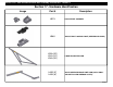
Series 8700 / 8800 Unitized Curtain Wall Assembly Instructions - Volume 5 Section 32 - Mounting Vent Assembly Into Unit Frame Releasable Arm Procedure 1 Secure Position 2 Loosen security screw. Security Screw Security Screw Mounting Bracket Top Plate Arm 3 4 Guide Shoe With Friction Pad Slide assembly upward. Limit Arm Track Allen Keyed Release Limit Arm Disengage assembly from mounting bracket.