Installation Instructions Sections 1 - 15 March 2013 PART NO.
Series 8700 / 8800 Unitized Curtain Wall Installation Instructions Series 8700 / 8800 Unitized Curtain Wall Installation Instructions Table Of Contents SECTION PAGE 1. General Notes and Guidelines………………………………………………………….. 3 - 4 2. Parts Identification………………………………………………………………………… 5 - 8 3. Static Starter Sill Preparation and Installation……………………………..………… 9 - 16 4. Dynamic Starter Sill Preparation and Installation…………………..……………….. 17 - 26 5.
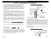
Series 8700 / 8800 Unitized Curtain Wall Installation Instructions Section 1: General Notes And Guidelines HANDLING / STORING / PROTECTING ALUMINUM The following guidelines are recommended to ensure early acceptance of your products and workmanship. A. HANDLE CAREFULLY - Store with adequate separation between components so the material will not rub together. Store the material off the ground. Protect materials against weather elements and other construction trades. B.
Series 8700 / 8800 Unitized Curtain Wall Installation Instructions Section 1: General Notes And Guidelines It is the responsibility of the glazing contractor to submit a statement from the sealant manufacturer indicating that glass and glazing materials have been tested for compatibility and adhesion with glazing sealants, and interpreting test results relative to material performance, including recommendations for primers and substrate preparation required to obtain adhesion.
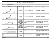
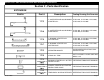
Series 8700 / 8800 Unitized Curtain Wall Installation Instructions Section 2 - Parts Identification EXTRUSION Profile Part # Tooling Drawing/Cut Formulas 4G99 7" STATIC STARTER SILL U4G99-001, U4G99-002 1H62 8" STATIC STARTER SILL U1H62-001, U1H62-002 7" GUTTER BASE MULLION ANCHOR REFERENCE FM01, FM22-FM25 PART DRAWINGS 8" GUTTER BASE MULLION ANCHOR REFERENCE FM02, FM26-FM29 PART DRAWINGS 17C8 FABRICATED # FM01, FM22FM25 17H9 FABRICATED # FM02, FM26FM29 EFCO 2009 Description 17C6 STARTE
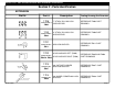
Series 8700 / 8800 Unitized Curtain Wall Installation Instructions Section 2 - Parts Identification EXTRUSION Profile Part # Description Tooling Drawing/Cut Formulas 17C3 7" CAPTURED AND SSG DYNAMIC U17C3-001, U17C3-002, U17C3-003, STARTER SILL U17C3-004, U17C3-005 17H8 8" CAPTURED AND SSG DYNAMIC U17H8-001, U17H8-002, U17H8-003, STARTER SILL U17H8-004, U17H8-005 17C5 7" DYNAMIC STARTER SILL GUTTER BASE U17C5-001, U17C5-002, U17C5-003, U17C5-004, U17C5-005 17H7 8" DYNAMIC STARTER SILL GUTTER BA
Series 8700 / 8800 Unitized Curtain Wall Installation Instructions Section 2 - Parts Identification EXTRUSION Profile Part # 17D6 FABRICATED # FM03 17J3 FABRICATED # FM04 17D1 FABRICATED # Description 7" STACK SILL MULLION ANCHOR BAR REFERENCE FM03 PART DRAWING 8" STACK SILL MULLION ANCHOR BAR REFERENCE FM04 PART DRAWING MULLION ANCHOR REFERENCE FM11 PART DRAWING FM11 17D2 HOOK ANCHOR LEFT (FM05) FABRICATED # FM05 & FM06 HOOK ANCHOR RIGHT (FM06) 17F3 FABRICATED FM07 17F4 FABRICATED FM08
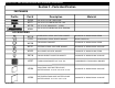
Series 8700 / 8800 Unitized Curtain Wall Installation Instructions Section 2 - Parts Identification FASTENERS Profile Part # Description SFQ5 M171 M170 1/4"-14 X 1 1/2" HWH #3 UC TEK 3 SG M169 1/2"-13 X 3 1/2" HX-MS 18-8 (FULL THREAD) Material 1/4"-14 X 1 1/2" HX- SMS 18-8 B 1/2"-13 X 1/2" SHSS W/ CP - STEEL ACCESSORIES EFCO 2009 WC19 LC23 HORIZONTAL STACK JOINT SEAL GASKET 60 SHORE "A" DURO BLACK EPDM HORIZONTAL STACK SPACER GASKET BLACK RIGID PVC WC20 FIN BAR BULB GASKET 70 SHORE "A" D
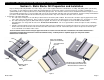
Series 8700 / 8800 Unitized Curtain Wall Installation Instructions Section 3 - Static Starter Sill Preparation and Installation Projects will be produced by EFCO in one of three ways: 1) As a stock length product where all fabrication, assembly, and glazing will be performed by the customer, or: 2) Prefabricated “knock down” where EFCO fabricates the materials, and the customer performs the assembly, and glazing, or: 3) EFCO will provide a completely fabricated, assembled and glazed product.
Series 8700 / 8800 Unitized Curtain Wall Installation Instructions Section 3 - Static Starter Sill Preparation and Installation d. A gutter base anchor (FM01 or FM02) is required at each intermediate vertical and jamb. Two are required at corner mullion conditions. The anchors are used to transfer wind load reactions from the verticals into the anchoring system. Before installation of the static starter sill, slide the appropriate number of gutter base anchors into each section of starter sill.
Series 8700 / 8800 Unitized Curtain Wall Installation Instructions Section 3 - Static Starter Sill Preparation and Installation 2. Verify that all job site conditions and accompanying substrates receiving the installation are in tolerance and are in accordance with the contract documents. 3. Pre-cleaning the substrates where the caulk joints will be applied later may be advisable prior to setting the starter sill.
Series 8700 / 8800 Unitized Curtain Wall Installation Instructions Section 3 - Static Starter Sill Preparation and Installation 5. Starting at the jamb, place the starter sill into the opening hard on the condition in the final position, excluding elevation. Match drill the substrates at the anchor locations and apply the anchors allowing for shim space under the starter sill. Refer to the approved shop drawings for type, size, and specific anchor details.
Series 8700 / 8800 Unitized Curtain Wall Installation Instructions Section 3 - Static Starter Sill Preparation and Installation 9. Using an approved solvent or cleaner, clean the sealant contact surfaces of the corner splice joint of all oils and other contaminants. 10. The starter sill will be spliced at corner conditions. Refer to the approved shop drawings for project specific joint size. A minimum joint size of 1/4” is required. 11.
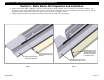
Series 8700 / 8800 Unitized Curtain Wall Installation Instructions Section 3 - Static Starter Sill Preparation and Installation 16. Using an approved solvent or cleaner, clean the sealant contact surfaces shown below of all oils and other contaminants. 17. The starter sill should be spliced at approximately every twenty-five feet. Refer to the approved shop drawings for specific locations and conditions. 18. Apply bond breaker tape (WM 79) to FM10 splice.
Series 8700 / 8800 Unitized Curtain Wall Installation Instructions Section 3 - Static Starter Sill Preparation and Installation 23. Using an approved solvent or cleaner, clean the sealant contact surfaces of the corner splice joint of all oils and other contaminants. 24. The starter sill will be spliced at corner conditions. Refer to the approved shop drawings for project specific joint size. A minimum joint size of 1/4” is required. 25.
Series 8700 / 8800 Unitized Curtain Wall Installation Instructions Section 3 - Static Starter Sill Preparation and Installation 30. As the starter sill sections are anchored into the final position, slide the gutter base anchors into position. The base anchor is flush with the end of the starter sill at the jambs, centered on the vertical at intermediate verticals, and flush with the mitered ends of the starter sill at corner conditions. 31.
Series 8700 / 8800 Unitized Curtain Wall Installation Instructions Section 4 - Dynamic Starter Sill Preparation and Installation 1. Preparation of the Dynamic Starter Sill: a. The Dynamic Gutter Base will be installed into the opening first. The Gutter Base may have an end dam pre-attached and sealed at the jamb conditions. Ensure that the end dam is properly applied and sealed to the starter sill as shown below. This is a critical seal and the joint must be carefully tooled to create a watertight seal.
Series 8700 / 8800 Unitized Curtain Wall Installation Instructions Section 4 - Dynamic Starter Sill Preparation and Installation 2. Verify that all job site conditions and accompanying substrates receiving the installation are in tolerance an are in accordance with the contract documents. 3. Pre-cleaning the substrates where the caulk joints will be applied later may be advisable prior to setting the starter sill.
Series 8700 / 8800 Unitized Curtain Wall Installation Instructions Section 4 - Dynamic Starter Sill Preparation and Installation 5. Starting at the jamb, place the starter sill base into the opening hard on the condition in the final position, excluding elevation. Match drill the substrates at the anchor locations and apply the anchors allowing for shim space under the starter sill base. Refer to the approved shop drawings for type, size, and specific anchor details.
Series 8700 / 8800 Unitized Curtain Wall Installation Instructions Section 4 - Dynamic Starter Sill Preparation and Installation 8. Using an approved solvent or cleaner, clean the sealant contact surfaces depicted below of all oils and other contaminants. The sealant manufacturer’s preparation and application instructions should be followed exactly. If sealant primer is required, apply it per the primer/sealant manufacturer’s instructions. 9.
Series 8700 / 8800 Unitized Curtain Wall Installation Instructions Section 4 - Dynamic Starter Sill Preparation and Installation 14. Set the next series of sections of starter sill base into the opening, butting together the sections at the corners, and allowing a nominal sized space between the sections at the intermediate splice locations. Refer to the final approved shop drawings for exact joint size.
Series 8700 / 8800 Unitized Curtain Wall Installation Instructions Section 4 - Dynamic Starter Sill Preparation and Installation 21. Using an approved solvent or cleaner, clean the sealant contact surfaces of the starter sill of all oils and other contaminants where the splice will be applied. The sealant manufacturer’s preparation and application instructions should be followed exactly. If sealant primer is required, apply it per the primer/sealant manufacturer’s instructions. 22.
Series 8700 / 8800 Unitized Curtain Wall Installation Instructions Section 4 - Dynamic Starter Sill Preparation and Installation 25. Using an approved solvent or cleaner, clean the sealant contact surfaces of the splice and starter sill of all oils and other contaminants where the splice will be applied. The sealant manufacturer’s preparation and application instructions should be followed exactly. If sealant primer is required, apply it per the primer/sealant manufacturer’s instructions. 26.
Series 8700 / 8800 Unitized Curtain Wall Installation Instructions Section 4 - Dynamic Starter Sill Preparation and Installation 34. Using an approved solvent or cleaner, clean the sealant contact surfaces of the starter sill of all oils and other contaminants where the silicone splice sleeve will be applied. The sealant manufacturer’s preparation and application instructions should be followed exactly. If sealant primer is required, apply it per the primer/sealant manufacturer’s instructions. 35.
Series 8700 / 8800 Unitized Curtain Wall Installation Instructions Section 4 - Dynamic Starter Sill Preparation and Installation 41. Using an approved solvent or cleaner, clean the sealant contact surfaces of the starter sill depicted below of all oils and other contaminants. The sealant manufacturer’s preparation and application instructions should be followed exactly. If sealant primer is required, apply it per the primer/ sealant manufacturer’s instructions. 42.
Series 8700 / 8800 Unitized Curtain Wall Installation Instructions Section 4 - Dynamic Starter Sill Preparation and Installation 47. Using an approved solvent or cleaner, clean the sealant contact surfaces of the starter sill of all oils and other contaminants where the splice will be applied. The sealant manufacturer’s preparation and application instructions should be followed exactly. If sealant primer is required, apply it per the primer/sealant manufacturer’s instructions. 48.
Series 8700 / 8800 Unitized Curtain Wall Installation Instructions Section 5 - Dynamic Starter Sill Anchor Installation 1. Assemble the starter sill anchors by attaching the anchor bar to the starter sill anchor (17C6) with (6) SFP9 fasteners. Offset anchors may be required at jamb conditions. Anchors may come to the field preassembled, depending on project requirements. Refer to the final approved shop drawings for anchor configurations, bolt sizes and other project specific information. 2.
Series 8700 / 8800 Unitized Curtain Wall Installation Instructions Section 5 - Dynamic Starter Sill Anchor Installation 3. Apply flat and lock washers and the serrated washers onto the anchor bolts. Turn the serrated washer (17D3) so that the teeth don't interlock to simplify anchor adjustments. Leave the nuts loose enough to allow free movement of the anchor assembly.
Series 8700 / 8800 Unitized Curtain Wall Installation Instructions Section 6 - Intermediate Floor Slab Anchor Installation 1. Set the slab anchors (17D4) into the opening inserting anchor bolts into the slots in the approximate locations required. Do not use shims between the slab anchor and the slab. Anchors are typically located at the mullion center line at intermediate locations. Jamb anchor locations vary. Refer to the approved final shop drawings for location. 2.
Series 8700 / 8800 Unitized Curtain Wall Installation Instructions Section 7 - Unit Inspection and Preparation for Installation 1. Before installing the units, follow this checklist to ensure they are ready for installation: a. Inspect the units to ensure that each unit has all external gaskets and screws. The WC19, WC20 and WC21 gaskets will be shop crimped in place. Verify these gaskets have been crimped securely to the frame. WC16 is a push-in type gasket.
Series 8700 / 8800 Unitized Curtain Wall Installation Instructions Section 7 - Unit Inspection and Preparation for Installation e. Using an approved solvent or cleaner, clean the sealant contact surfaces of the expansion cavity of the stack sill and 17D9 of all oils and other contaminants. See Figure 62. f. Apply a generous amount of sealant in both ends of the cavity approximately 4” long. See Figure 62. g.
Series 8700 / 8800 Unitized Curtain Wall Installation Instructions Section 8 - Setting Units at Static Starter Sills 1. 2. 3. 4. Static starter sills are used with installations that don’t require provisions for vertical movements at the beginning floor of the curtain wall. Units are typically installed from left to right from as seen from the exterior of the building. Install each frame unit in sequence, starting at the left jamb unit.
Series 8700 / 8800 Unitized Curtain Wall Installation Instructions Section 8 - Setting Units at Static Starter Sills 1. If the starter sill was properly installed and the unit is square and is setting hard on the starter sill, the unit will be at the proper elevation and will be level and plumb from side to side. 2. Compare the jamb unit to established bench marks and move the unit side to side to position it laterally to the final required location. 3.
Series 8700 / 8800 Unitized Curtain Wall Installation Instructions Section 8 - Setting Units at Static Starter Sills 6. Set the next unit after the jamb unit by nesting the vertical stacking mullions together without snapping them. See Figure 74 on page 35. 7. Lower the unit to the static starter sill, but still be approximately 1/2” above the engagement leg of the starter sill. The unit hook anchors should have enough vertical adjustment to hook onto the slab anchors. See Figure 73.
Series 8700 / 8800 Unitized Curtain Wall Installation Instructions Section 8 - Setting Units at Static Starter Sills 8. Once the unit is approximately 1/2” above the engagement leg of the starter sill, use clamps to snap the mullions together. Place one clamp at the center of the mullion at the bottom of the units. Use wood blocks to protect the finished surfaces of the mullions. Tighten the clamp until the mullion halves begin to snap together.
Series 8700 / 8800 Unitized Curtain Wall Installation Instructions Section 8 - Setting Units at Static Starter Sills 11. Adjust the free end of the unit for plumb, parallel to the plane of the wall, by sliding the slab anchor forward or backward until the unit is plumb. See Figure 76 below. 12. Rotate the serrated washers where the serrations align with the serrations in the anchor and secure the slab anchor’s anchor bolts. 13.
Series 8700 / 8800 Unitized Curtain Wall Installation Instructions Section 9 - Setting Units at Dynamic Starter Sills 1. 2. 3. 4. Dynamic starter sills are used with installations that require provisions for vertical movements at the beginning floor of the curtain wall. Units are typically installed from left to right as seen from the exterior of the building. Install each frame unit in sequence, starting at the left jamb unit. Units are lifted by the splice bars attached at the head of each unit.
Series 8700 / 8800 Unitized Curtain Wall Installation Instructions Section 8 - Setting Units at Dynamic Starter Sills 8. 9. 10. 11. Compare the jamb unit to established bench marks and move the unit side to side to position it laterally to the required location. Adjust the unit for plumb, parallel to the plane of the wall, by sliding the slab anchor forward or backward until the unit is plumb. See Figure 82.
Series 8700 / 8800 Unitized Curtain Wall Installation Instructions Section 8 - Setting Units at Dynamic Starter Sills 14. Adjust the starter sill anchor so that it aligns with the vertical. The anchor can be slid from side to side on the insert. Ensure the anchor is pressed against the back of the starter sill. Rotate the washers at the starter sill anchor so that the serrations align with the serrations in the starter sill anchor. 15.
Series 8700 / 8800 Unitized Curtain Wall Installation Instructions Section 9 - Setting Units at Dynamic Starter Sills 16. Set the next unit after the jamb unit by nesting the vertical stacking mullions together without snapping them. See Figure 88 on page 41. 17. Lower the units enough to engage the slab anchor bar (FM03 or FM04) at the sill, but still be approximately 1/2” above the engagement leg of the starter sill.
Series 8700 / 8800 Unitized Curtain Wall Installation Instructions Section 9 - Setting Units at Dynamic Starter Sills 19. Once the unit is approximately 1/2” above the engagement leg of the starter sill, use clamps to snap the mullions together. Place one clamp at the center of the mullion at the bottom of the units. Use wood blocks to protect the finished surfaces of the mullions. Tighten the clamp until the mullion halves begin to snap together.
Series 8700 / 8800 Unitized Curtain Wall Installation Instructions Section 9 - Setting Units at Dynamic Starter Sills 20. Before lowering the unit down any farther, insert the remaining HC07 foam backer from the unit that is already set into the cavity by using a putty knife or similar tool. Note: This is a very critical step that is easily forgotten and could cause units to leak if missed. See Figure 90. 21.
Series 8700 / 8800 Unitized Curtain Wall Installation Instructions Section 9 - Setting Units at Dynamic Starter Sills 24. Compare the unit to established bench marks and move the unit side to side to position it laterally to the required location. At the stacked mullions the mullion width should be 3”. 25. Adjust the starter sill anchor so that it aligns with the vertical. The anchor can be slid from side to side on the insert. Ensure the anchor is pressed against the back of the starter sill.
Series 8700 / 8800 Unitized Curtain Wall Installation Instructions Section 9 - Setting Units at Dynamic Starter Sills 30. Set the unit to the required elevation height and level it by turning the jack bolt at each mullion anchor clockwise to raise, or counterclockwise to lower the unit in to the final position. 31. Match drill the slab anchors through the hook anchors on both sides of the unit, and install the pinning screws to lock the frame unit into the final position. See Figures 95 and 96. 32.
Series 8700 / 8800 Unitized Curtain Wall Installation Instructions Section 10 - Setting Typical Intermediate Units 1. Install each frame unit in sequence, starting at the left jamb unit. 2. Lift the jamb unit with the splice bars at the head of the unit. 3. Ensure the HC07 caulk backer has been inserted into the sill as shown in Figures 62 and 64 on page 31. Note that jamb units will receive HC07 on both ends of the sill.
Series 8700 / 8800 Unitized Curtain Wall Installation Instructions Section 10 - Setting Typical Intermediate Units 8. 9. 10. 11. Compare the jamb unit to established bench marks and move the unit side to side to position it laterally to the required location. Adjust the unit for plumb, parallel to the plane of the wall, by sliding the slab anchor forward or backward until the unit is plumb. See Figure 101.
Series 8700 / 8800 Unitized Curtain Wall Installation Instructions Section 10 - Setting Typical Intermediate Units 14. Set the next unit after the jamb by nesting the vertical stacking mullions together without snapping them. See Figure 103 on page 48. 15. Lower the units enough to engage the unit splice bar (FM13, FM14 at 7” system) (FM15, FM16 at 8” system) at the sill but still be approximately 1/2” above the engagement leg of the starter sill.
Series 8700 / 8800 Unitized Curtain Wall Installation Instructions Section 10 - Setting Typical Intermediate Units 17. Once the unit is approximately 1/2” above the engagement leg of the gutter at the stack joint, use clamps to snap the mullions together. Place one clamp at the center of the mullion at the bottom of the units. Use wood blocks to protect the finished surfaces of the mullions. Tighten the clamp until the mullion halves begin to snap together.
Series 8700 / 8800 Unitized Curtain Wall Installation Instructions Section 10 - Setting Typical Intermediate Units 18. Before lowering the unit down any farther, insert the remaining HC07 foam backer from the unit that is already set into the cavity by using a putty knife or similar tool. Note: This is a very critical step that is easily forgotten and could cause units to leak if missed. See Figure 107. 19.
Series 8700 / 8800 Unitized Curtain Wall Installation Instructions Section 10 - Setting Typical Intermediate Units 22. Compare the unit to established bench marks and move the unit side to side to position it laterally to the required location. At the stacked mullions the mullion width should be 3”. 23. Adjust the unit for plumb, parallel to the plane of the wall, by sliding the slab anchor forward or backward until the unit is plumb. See Figure 110. 24.
Series 8700 / 8800 Unitized Curtain Wall Installation Instructions Section 10 - Setting Typical Intermediate Units 26. Set the unit to the required elevation height and level it by turning the jack bolt at each mullion anchor clockwise to raise, or counterclockwise to lower the unit in to the final position. 27. Match drill the slab anchors through the hook anchors on both sides of the unit, and install the pinning screws to lock the frame unit into the final position. See Figures 111 and 112. 28.
Series 8700 / 8800 Unitized Curtain Wall Installation Instructions Section 11 - Setting Assembled (One Piece) Corner Units 1. Follow the check list in “Section 7 - Unit Inspection and Preparation for Installation” on pages 30 and 31 before installing the corner units to ensure units are ready for installation. 2. Verify the adjacent unit has been installed properly with regard to established bench marks before installing corner units.
Series 8700 / 8800 Unitized Curtain Wall Installation Instructions Section 11 - Setting Assembled (One Piece) Corner Units 6. Refer to “Section 8 - Setting Units at Static Starter Sills” on pages 32 - 36 when installing corner units at the static starter sill locations. The inside 90° corner static starter sill condition is shown below. See Figure 114. The outside 90° corner static starter sill condition is shown in Figure 115.
Series 8700 / 8800 Unitized Curtain Wall Installation Instructions Section 11 - Setting Assembled (One Piece) Corner Units 6. Refer to “Section 9 - Setting Units at Dynamic Starter Sills” on pages 37 - 44 when installing corner units at the dynamic starter sill locations. The inside 90° corner dynamic starter sill condition is shown below. See Figure 117. The outside 90° corner dynamic starter sill condition is shown in Figure 118.
Series 8700 / 8800 Unitized Curtain Wall Installation Instructions Section 11 - Setting Assembled (One Piece) Corner Units 6. Refer to “Section 10 - Setting Typical Intermediate Units” on pages 45 - 51 when installing corner units at intermediate floor slab locations. The inside 90° corner anchor condition is shown below. See Figure . The outside 90° corner anchor condition is shown in Figure .
Series 8700 / 8800 Unitized Curtain Wall Installation Instructions Section 12 - Applying Critical Seals 1. Once the two units are installed, a splice is required at the gutter at the top of the units. Clean the gutter sill sealant contact surfaces using an approved solvent or cleaner of all oils and other contaminants where the gutter splice will be applied. The sealant manufacturer’s preparation and application instructions should be followed exactly.
Series 8700 / 8800 Unitized Curtain Wall Installation Instructions Section 12 - Applying Critical Seals 4. Lay the gutter splice into the bed of sealant. Press the gutter splice up under the WC19 gasket track. See Figure 123. Smooth the splice down onto the gutter, forcing out all air bubbles. 5. Apply sealant around the perimeter of the gutter splice. Tool the sealant to ensure a watertight seal at the splice. See Figure 124. 6.
Series 8700 / 8800 Unitized Curtain Wall Installation Instructions Section 13 - Applying Typical Perimeter Seals 1. The typical jamb and starter sill are as shown below in Figures 125 and 126. The line of sealant at the jamb will follow the front edge of the back member. 2. The condition at the head is job specific. Refer to approved shop drawings for sealant details. 3.
Series 8700 / 8800 Unitized Curtain Wall Installation Instructions Section 13 - Applying Typical Perimeter Seals 4. Insert a backer rod into the reveal on the end of the starter sill. Recess the backer rod into the cavity of the reveal at a minimum of 1/4”. Seal off the end of cavity with sealant and marry it into the end dam sealant. See Figure 127. 5. Special care is needed to ensure that the end dam is properly sealed and marries into the perimeter sealant correctly at the jamb to sill condition.
Series 8700 / 8800 Unitized Curtain Wall Installation Instructions Section 13 - Applying Typical Perimeter Seals 7. At jamb conditions of the unit stack joint, an end dam is pre-installed. Special care is needed to ensure the end dam is properly sealed and marries into the perimeter sealant correctly. See Figures 131 - 132. 8. Place a piece of backer rod between the end dam and the jamb. The backer rod will run from the front face of the end dam to the engagement leg.
Series 8700 / 8800 Unitized Curtain Wall Installation Instructions Section 14 - Deglaze / Re-glaze Procedures - Captured System 1. The captured system units are structural silicone glazed to the frame. The deglaze and re-glaze procedure must be performed from a swing stage or man lift from the exterior of the building. Follow the sealant manufacture’s sealant application instruction for deglazing and re-glazing. When deglazing an opening or openings at a captured unit, follow these instructions: a.
Series 8700 / 8800 Unitized Curtain Wall Installation Instructions Section 14 - Deglaze / Re-glaze Procedures - Captured System 2. When re-glazing an opening or openings at a captured unit, follow these instructions: a. Using an approved solvent or cleaner, clean the glazing surfaces of all oils and other contaminants. The sealant manufacturer’s preparation and application instructions should be followed exactly. Fresh sealant will adhere to cured sealant without primer.
Series 8700 / 8800 Unitized Curtain Wall Installation Instructions Section 14 - Deglaze / Re-glaze Procedures - Captured System 3. When re-glazing an opening or openings at a captured unit follow these instructions: a. Carefully insert new setting blocks in the locations as noted in the approved shop drawings. b. Clean the new glass or panel and set it in place, centered in the opening, setting on the setting blocks. Do not contaminate the sealant contact surfaces of the glazing during handling.
Series 8700 / 8800 Unitized Curtain Wall Installation Instructions Section 15 - Deglaze / Re-glaze Procedures - SSG System 1. The deglaze and re-glaze procedure must be performed from a swing stage or man lift from the exterior of the building. Follow the sealant manufacture’s sealant application instruction for deglazing and re-glazing. When deglazing an opening or openings at a structural silicone glazed unit follow these instructions: a.
Series 8700 / 8800 Unitized Curtain Wall Installation Instructions Section 15 - Deglaze / Re-glaze Procedures - SSG System 2. When re-glazing an opening or openings at a structural silicone glazed, follow these instructions: a. Using an approved solvent or cleaner, clean the glazing surfaces of all oils and other contaminants. The sealant manufacturer’s preparation and application instructions should be followed exactly. Fresh sealant will adhere to cured sealant without primer.
Series 8700 / 8800 Unitized Curtain Wall Installation Instructions Section 15 - Deglaze / Re-glaze Procedures - SSG System 3. When re-glazing an opening or openings at a captured unit follow these instructions: a. Carefully insert new setting blocks in the locations as noted in the approved shop drawings. b. Clean the new glass or panel and set it in place, centered in the opening, setting on the setting blocks. Do not contaminate the sealant contact surfaces of the glazing during handling.
Series 8700 / 8800 Unitized Curtain Wall Installation Instructions Section 15 - Deglaze / Re-glaze Procedures - SSG System d. Tool the sealant around the perimeter of the glazing, packing the sealant into the joint, to ensure any voids or air bubbles in the sealant are eliminated. Carefully relocate the glazing retainers to expose inaccessible areas behind the retainer, and tool the sealant at those areas. Pay particular attention at the corners of the glazing. e.
Series 8700 / 8800 Unitized Curtain Wall Installation Instructions Section 15 - Deglaze / Re-glaze Procedures - SSG System f. When the structural silicone joints are fully cured, remove the temporary retainers. Properly clean and prepare the joints, apply backer rod and the weather seal. Tool the joint to form an hour glass shaped sealant joint as shown. Remove temporary retainers , insert backer rod, and apply weather seals, and tool as shown.