
Installation Instructions User guide

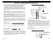
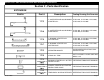
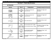
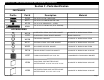
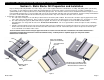
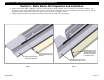
Table Of Contents
- Table Of Contents
- Section 1: General Notes And Guidelines
- Section 2 - Parts Identification
- Section 3 - Static Starter Sill Preparation and Installation
- Section 4 - Dynamic Starter Sill Preparation and Installation
- Section 5 - Dynamic Starter Sill Anchor Installation
- Section 6 - Intermediate Floor Slab Anchor Installation
- Section 7 - Unit Inspection and Preparation for Installation
- Section 8 - Setting Units at Static Starter Sills
- Section 9 - Setting Units at Dynamic Starter Sills
- Section 10 - Setting Typical Intermediate Units
- Section 11 - Setting Assembled (One Piece) Corner Units
- Section 12 - Applying Critical Seals
- Section 13 - Applying Typical Perimeter Seals
- Section 14 - Deglaze / Re-glaze Procedures - Captured System
- Section 15 - Deglaze / Re-glaze Procedures - SSG System

EFCO 2009 Page 4
Series 8700 / 8800 Unitized Curtain Wall Installation Instructions
Section 1: General Notes And Guidelines
It is the responsibility of the glazing contractor to submit a statement from
the sealant manufacturer indicating that glass and glazing materials have
been tested for compatibility and adhesion with glazing sealants, and
interpreting test results relative to material performance, including
recommendations for primers and substrate preparation required to obtain
adhesion. The chemical compatibility of all glazing materials and framing
sealants with each other and with like materials used in glass fabrication
must be established.
Maintain caulk joints as shown in the approved shop drawings. A 1”
minimum joint is required at the head and jamb condition to accommodate
installation, building movements, and thermal expansion and contraction.
H. STRUCTURAL SEALANT JOINTS - The maximum allowable size of the
glass lite is controlled by the width and depth of the structural silicone joint
combined with the specified design wind load (PSF or Pa). The stress on
the structural silicone must not exceed 20 PSI (137 KPa) for a 6:1 safety
factor.
In order to determine the structural silicone sealant contact width or bite
which adheres the glass to the frame, a calculation must be performed on a
job by job basis. The formula which determines the sealant width is based
on using a trapezoidal load distribution rule. This formula is expressed as
follows:
Structural Sealant = 0.5 x Short Span (ft) x Wind load (lb/ft²)
Bite or Contact Width (in) Sealant Design Strength (=20 lb/in²) x 12 in/ft
Example: Lite size is 4’0” x 5’0” and wind load for the project is 60 psf.
Structural Sealant = 0.5 x 4’ x 60 psf
or 120 or .500”
Bite or Contact Width (in) 20 x 12 240
Sealant manufacturers, as a general rule, specify the structural sealant
depth (glue line) to be one half of the contact width for a 2:1 width to height
ratio. The glue line should not exceed 3/8” thickness nor be less than 1/4”
thick. The standard joint size for Series 8000 is 1/2” x 1/4”. Note: Weather
seals must be applied a minimum of four hours after the application of the
SSG sealant joint to allow for proper cure time.
I. SECONDARY SEALANT JOINT DESIGN - The design of the secondary
sealant joint is based on the 50:50 load sharing principal where the I.G. unit
is comprised of two symmetrical lites of glass. The secondary sealant joint
that adheres the two lites of glass together only carries half the wind load
applied to the I.G. unit. Since the load is halved, the secondary sealant
contact width is half that of the SSG joint. Using the example earlier for the
1/2” x 1/4” SSG joint, the secondary sealant contact width for the I.G. unit in
the example is 1/4”.
Edge deletion is required on the coated surface (#2 or #3) for hard or soft
coated glazing products.
SEALANT DEPTH
(GLUE LINE)
STRUCTURAL SEALANT
CONTACT WIDTH
WEATHER SEAL
(Do not apply until the
SSG sealant joint has
cured for 4 hours.)
SPACER GASKET
SSG SEALANT JOINT
SECONDARY SEALANT JOINT DETAIL
STANDARD TUBULAR
SPACER RECOMMENDED
SECONDARY SEALANT
CONTACT WIDTH
SECONDARY SEALANT JOINT DETAIL