
Installation Instructions User guide

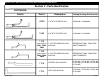
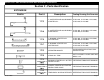
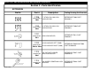
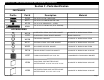
Table Of Contents
- Table Of Contents
- Section 1: General Notes And Guidelines
- Section 2 - Parts Identification
- Section 3 - Static Starter Sill Preparation and Installation
- Section 4 - Dynamic Starter Sill Preparation and Installation
- Section 5 - Dynamic Starter Sill Anchor Installation
- Section 6 - Intermediate Floor Slab Anchor Installation
- Section 7 - Unit Inspection and Preparation for Installation
- Section 8 - Setting Units at Static Starter Sills
- Section 9 - Setting Units at Dynamic Starter Sills
- Section 10 - Setting Typical Intermediate Units
- Section 11 - Setting Assembled (One Piece) Corner Units
- Section 12 - Applying Critical Seals
- Section 13 - Applying Typical Perimeter Seals
- Section 14 - Deglaze / Re-glaze Procedures - Captured System
- Section 15 - Deglaze / Re-glaze Procedures - SSG System

EFCO 2009 Page 6
Series 8700 / 8800 Unitized Curtain Wall Installation Instructions
Section 2 - Parts Identification
EXTRUSION
Profile Part #
Description
Tooling Drawing/Cut Formulas
17C3
7" CAPTURED AND SSG DYNAMIC
STARTER SILL
U17C3-001, U17C3-002, U17C3-003,
U17C3-004, U17C3-005
17H8
8" CAPTURED AND SSG DYNAMIC
STARTER SILL
U17H8-001, U17H8-002, U17H8-003,
U17H8-004, U17H8-005
17C5
7" DYNAMIC STARTER SILL
GUTTER BASE
U17C5-001, U17C5-002, U17C5-003,
U17C5-004, U17C5-005
17D3
SERRATED WASHER
AS REQUIRED PER STRUCTURAL
CALCULATIONS
DYNAMIC STARTER SILL GUTTER
REVEAL SPLICE
REFERENCE FM09 PART DRAWING
TEMPORARY GLAZING RETAINER REFERENCE FM12 PART DRAWING
17H7
8" DYNAMIC STARTER SILL
GUTTER BASE
U17H7-001, U17H7-002, U17H7-003,
U17H7-004, U17H7-005
17D5
STACK SILL TRIM
CUT TO LENGTH - HORIZ. UNIT DIM.
MINUS .125
17D0
FABRICATED #
FM10
17C4
FABRICATED #
FM09
STACTIC STARTER SILL GUTTER
REVEAL TUBE SPLICE
REFERENCE FM10 PART DRAWING
17L6
FABRICATED #
FM12