Quick Set can system Installation Instructions Part NO.
SECTION I II TABLE OF CONTENTS 1 GENERAL NOTES PARTS IDENTIFICATION A) B) C) D) III PAGE 2-3 4-6 7-8 9-10 901 PARTS IDENTIFICATION 902 PARTS IDENTIFICATION 903 PARTS IDENTIFICATION 904 PARTS IDENTIFICATION FABRICATION A) DRILLING TEMPLATE (901/902 INTERMEDIATE HORIZONTAL) B) DRILLING TEMPLATE (903/904 INTERMEDIATE HORIZONTAL) C) HEAD AND SILL CAN 11 12 13-15 D) HEAD AND SILL CAN FILLER 1) CAPTURED MULLION SYSTEM 2) BUTT GLAZED SYSTEM E) VERTICAL INTERMEDIATE AND 2 PIECE JAMB 16 16 17-19 20-21 22-
SECTION I - GENERAL NOTES PAGE 1 EFCO Series 901 (4 1/2" Nonthermal System) EFCO Series 902 (5 1/4" Thermal System) EFCO Series 903 (3 1/4" Nonthermal System) EFCO Series 904 (4" Thermal System) Series 901 & 903 accommodates 1/4" glazing. Series 902 & 904 accommodates 1" glazing. The "QUICK SET" storefront family is a ribbon window system, having many advantages over other systems due to the minimum fabrication and installation steps.
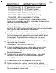
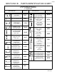
PAGE 2 SECTION II A - PARTS IDENTIFICATION CHART SERIES 901 QUICK SET 4 1/2" NONTHERMAL FRAMING 1/4" GLAZING DESCRIPTION HEAD AND SILL 4 1/2" CAN PART NO.
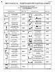
PAGE 3 SECTION II A - PARTS IDENTIFICATION CHART SERIES 901 QUICK SET 4 1/2" NONTHERMAL FRAMING 1/4" GLAZING DESCRIPTION INTERMEDIATE HORIZONTAL SHEAR 9470 F076 F077 BLOCK USE 2 1/2" C.O.C. DOOR HEADER SHEAR BLOCK 901 - 9598 2" DOOR JAMB as DOOR HEADER SHEAR BLOCK 901 - 9597 (1) FS67, (2) STV2, (2) MRF1/(2) MRF6 TRANSOM HEADER SHEAR BLOCK PACKAGE USE w/ 9472 EX32 K176 DESCRIPTION PART NO. SHEAR BLOCK PKG. FOR #8583 HORIZ. at 135° S.S.G.
PAGE 4 SECTION II B - PARTS IDENTIFICATION CHART SERIES 902 QUICK SET 5 1/4" THERMAL FRAMING 1" GLAZING DESCRIPTION HEAD and SILL 5 1/4" CAN USE 9485 CAN FILLER CAN FILLER USE w/ 9484, 9845 OR 1G66 THERMAL STRUT HEAD and SILL 5 1/4" CAN PART NO.
PAGE 5 SECTION II B - PARTS IDENTIFICATION CHART SERIES 902 QUICK SET 5 1/4" THERMAL FRAMING 1" GLAZING DESCRIPTION TRANSOM HEAD USE w/ 7861 PART NO.
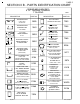
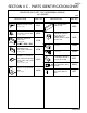
PAGE 6 SECTION II B - PARTS IDENTIFICATION CHART SERIES 902 QUICK SET 5 1/4" THERMAL FRAMING 1" GLAZING DESCRIPTION INTERMEDIATE HORIZONTAL SHEAR BLOCK USE w/ 8583 or 8500 PART NO. HEAD/SILL CAN SPLICE K176 TRANSOM HEADER SHEAR BLOCK PACKAGE USE w/ 9539 (1) F344, (1) F345, (8) STT6, (4) MRF6 EX32 K377 (1) WM01 K433 (1) FT14, (4) SFP8 FT14 (USE WITH 9484) 25 PER PACKAGE (1) F015, (1) WM96, (1) F365, (3) MRF8, (1) S110 HEAD/SILL CAN ANCHOR CLIP USE w/ 9578 at JAMBS PART NO.
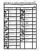
PAGE 7 SECTION II C - PARTS IDENTIFICATION CHART SERIES 903 QUICK SET 3 1/4" NONTHERMAL FRAMING 1/4" GLAZING DESCRIPTION HEAD and SILL 3 1/4" CAN PART NO. DESCRIPTION PART NO.
PAGE 8 SECTION II C - PARTS IDENTIFICATION CHART SERIES 903 QUICK SET 3 1/4" NONTHERMAL FRAMING 1/4" GLAZING DESCRIPTION INTERMEDIATE HORIZONTAL SHEAR BLOCK USE w/ 958 (1) F021, (3) MRF7 HEAD/SILL CAN ANCHOR CLIP USE w/ 9575 at JAMB FT15 (1) FT15, (4) SFP8 HEAD/SILL CAN SPLICE USE w/ 9476 7885 25 PER PACKAGE PART NO. K141 K434 K378 DESCRIPTION 1/4" SETTING BLOCK USE w/ 9476 HORIZONTAL END DAM for 1/4" GLZ. at 2 PC.
PAGE 9 SECTION II D - PARTS IDENTIFICATION CHART SERIES 904 QUICK SET 4" THERMAL FRAMING 1" GLAZING DESCRIPTION HEAD and SILL CAN FLAT BOTTOM PART NO.
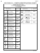
PAGE 10 SECTION II D - PARTS IDENTIFICATION CHART SERIES 904 QUICK SET 4" THERMAL FRAMING 1" GLAZING CONT. DESCRIPTION PART NO. DESCRIPTION INTERMEDIATE HORIZONTAL SHEAR BLOCK USE w/ 9564 (1) F021, (3) MRF7 1/4" GLAZING ADPT. at BUTT GLAZED MULL USE w/ 9558 or 9559 OUTSIDE GLAZED HEAD/SILL SPLICE USE w/ 8716 O.G. CAN WATER DEFLECTOR @ INT. HORIZONTAL K141 1" SETTING BLOCK at SILL CAN 9574 PART NO.
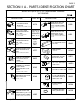
PAGE 11 SECTION III A - FABRICATION DRILLING TEMPLATE - 901/902 INTERMEDIATE HORIZONTAL 2 PC. JAMBS CAPTURED VERTICALS 9576 OR 9579 9578 1.000 .625 8594 OR 8593 .149 DIA. (#25 DRILL) FOR #10-24 x 1 3/4" P.H.S.M.S. (3) MRF8 .062 1" NOTCH 5/8" NOTCH AT JAMB AT VERTICALS NOTE: OFFSET .590 TOP OF HORIZONTAL .312 #10-24x 1/2" F.H. (S110) 1.625 .750 901/902 SYSTEMS FRONT OF MULLION 8583 K176 (9470) 8499 903/904 SYSTEMS FRONT OF MULLION TOP OF HORIZONTAL 1.
PAGE 12 SECTION III B - FABRICATION DRILLING TEMPLATE - 903/904 INTERMEDIATE HORIZONTAL 2 PC. JAMB 9579 OR 9576 9575 CAPTURED VERTICALS 1.000 .625 8594 OR 8593 .062 NOTE: OFFSET .149 DIA. (#25 DRILL) .475 FOR #10-24 x 1 3/4" P.H.S.M.S. (3) MRF8 .875 TOP OF HORIZONTAL .313 9586/9564 .500 9565 K141 (9567) 903/904 SYSTEMS FRONT OF MULLION 901/902 SYSTEMS FRONT OF MULLION TOP OF HORIZONTAL 9558 .875 9559 .
SECTION III C - FABRICATION PAGE 13 HEAD AND SILL CAN INCLUDES CAPTURED AND BUTT GLAZED MULLION SYSTEMS STEP 1) Measure the opening to determine the cut length of the head and sill frame components. Allow for shims if applicable. STEP 2) Cut head and sill cans to frame width. This includes any "2" color covers that are being used. NOTE: Expansion/splice joints are required in elevations that exceed 20’-0" in width.
PAGE 14 SECTION III C - FABRICATION HEAD AND SILL CAN (CONT.) INCLUDES CAPTURED AND BUTT GLAZED MULLION SYSTEMS TAP LIGHTLY TO SNAP IN PLACE HOOK COVER OVER LEG CRIMP THIS LEG SLIGHTLY TO PREVENT COVER FROM WALKING OUT OF POSITION WITH THERMAL EXPANSION. DRILL 1/4" DIA. WEEP HOLES THRU COVER AND SILL OPTIONAL SEAL (LEAVE 1/4" SPACE AT WEEP HOLES) LOCATE PRIMARY SEAL BEHIND COVER LEG. [FIG. 3] STEP 4) 90 AND 135 CORNER FABRICATION Head and sill cans are mitered for inside or outside corners.
PAGE 15 SECTION III C - FABRICATION HEAD AND SILL CAN (CONT.) STEP 5) Weep Baffle Installation APPLY A SMALL AMOUNT OF SILICONE TYPE 1/2 HCW6 SEALANT TO THE BAFFLES THAT WILL STRADDLE THE DRILLED WEEP HOLE, AND LOCATE THEM OVER THE WEEP HOLES AS SHOWN. DO NOT PLUG THE WEEP HOLES WITH SEALANT. CUT HCW6 IN HALF TO SEALANT CREATE CORRECT SIZE BAFFLES. SEE FIG. 17 ON PAGE 23. BAFFLE BAFFLE [FIG.
PAGE 16 SECTION III D - FABRICATION HEAD AND SILL CAN FILLER 1) CAN FILLER CUT LENGTHS (CAPTURED MULLION SYSTEMS) Step 1) Determine center lines of each vertical mullion. Step 2) Jamb to first mullion cut length = End of head/sill can to center line of first mullion minus 1 1/2". Step 3) Mullion to mullion cut length = Center line to center line minus 1". (Head and sill cans run through. Can fillers run mullion to mullion, and mullion to jamb.
SECTION III E - FABRICATION PAGE 17 VERTICAL INTERMEDIATE AND 2 PIECE JAMB (BUTT GLAZED and CAPTURED MULLION SYSTEMS) STEP 1) Cut the captured mullion/jamb backs to the lengths shown in chart A below. This will allow 1/8" clearance inside the head can. Cut the butt glazed mullions to the lengths shown in chart A below. This will allow 1/4" minimum clearance inside the head can. * Cut the captured mullion face and the 2 pc. jamb face to the D.L.O. height.
SECTION III E - FABRICATION VERTICAL INTERMEDIATE AND 2 PIECE JAMB PAGE 18 (CONT.) (BUTT GLAZED and CAPTURED MULLION SYSTEMS) STEP 2) Notch the top of the mullion and jamb face 1/8" x 1/4" as shown in Fig. 9 below. This prep is for ease of installation of the jamb and vertical mullion. 8594 8593 9579 or 9576 1/4" [FIG.
SECTION III E - FABRICATION VERTICAL INTERMEDIATE AND 2 PIECE JAMB PAGE 19 (CONT.) (BUTT GLAZED and CAPTURED MULLION SYSTEMS) STEP 3) If horizontal intermediates are incorporated, drill for shear block attachment screws using the drilling templates on pages 11 & 12. Typical drilled members are shown in Fig. 10 below. Jamb members will have preps on one side only. 9575 9578 [FIG. 10] STEP 4) Cut length for the vertical mullion and jamb face is similar.
SECTION III F - FABRICATION PAGE 20 INSULBAR INTERMEDIATE VERTICAL STEP 1) Cut the thermal strut vertical mullion to the length shown in [CHART "A"] on page 17 (SECTION III E - FABRICATION). STEP 2) Notch the top of the mullion face 1/8" x 1/4" as shown in Fig. 12. This prep is for ease of installation of the vertical mullion. STEP 3) Notch the TOP of the mullion to leave the appropriate portion as shown in Fig. 12 below.
SECTION III F - FABRICATION THERMAL STRUT INTERMEDIATE VERTICAL PAGE 21 (CONT.) STEP 4) Notch the BOTTOM of the mullion to leave the appropriate portion as shown in Fig. 13 below. The 2" dimension taken from the exterior face will be applicable to all solid vertical intermediate mullion with 1" glazing. COMPOSITE #1G41 SHOWN OTHER MULLIONS ARE SIMILAR 9546 2" {S904 1 25/32" @ #9468 & #9477 CAN 3" (VARIES) [FIG.
SECTION III G - FABRICATION PAGE 22 INTERMEDIATE HORIZONTAL HORIZONTAL CUT LENGTH FORMULAS CUT LENGTH = EXTERIOR D.L.O. + 1" {at 2 pc. JAMB to BUTT GLAZED MULLION CUT LENGTH = EXTERIOR D.L.O. + 1 5/8" {at 2 pc. JAMB to CAPTURED VERTICAL MULLION CUT LENGTH = EXTERIOR D.L.O. + 1 1/4" {at CAPTURED VERTICAL MULLION to CAPTURED VERTICAL MULLION CUT LENGTH = EXTERIOR D.L.O.
PAGE 23 SECTION III G - FABRICATION INTERMEDIATE HORIZONTAL (CONT.) STEP 1) Cut horizontal face member to span 3 lites (or a maximum of 15’-0"). Allow 1/4" at splice joints for expansion. Splice ONLY at center lines of vertical mullions. See Fig. 16 below. D.L.O. INTERIOR 2" D.L.O. 2" D.L.O. 2" D.L.O. [FIG. 16] 1/4" HORIZONTAL FACE LENGTH (15 ft. max.
PAGE 24 SECTION III G - FABRICATION INTERMEDIATE HORIZONTAL (Cont.) CUT LENGTH FOR GLASS STOP = D.L.O. MINUS 1/32". VERTICAL to VERTICAL - INTERIOR D.L.O. CUT LENGTH FOR FACE MEMBER = 3 Lites - Not to exceed 15’ at BUTT GLAZE VERTICAL APPLICATIONS. SYSTEM & DEPTH INTERM. HORIZ. SHEAR BLOCK REQUIRED EXTRUSION NOS.
SECTION IV A - INSTALLATION PAGE 25 HEAD AND SILL CAN ANCHORING STEP 1) Fasten head and sill cans to surround through back portion of the can shape. Seal over all fastener heads in sill can. See Fig. 20 below. 901/903 - HN30 END DAMS 902/904 - HN31 END DAMS END DAMS AT JAMBS ONLY 1/4" DIAMETER MINIMUM FASTENERS AT 3" EACH SIDE OF VERTICAL MULLIONS AND 24" MAXIMUM ON CENTER. (TYPICAL ALL SYSTEMS) SEALANT SHIMS ARE OPTIONAL WITH THESE HEAD/SILL CANS #9479 - S901 #9484 - S902 #9476 - S903 [FIG.
SECTION IV A - INSTALLATION PAGE 26 HEAD AND SILL CAN SPLICE STEP 1) The main purpose of this operation is to ensure a water tight seal between the two lengths of the sill can and prevent water from entering the interior of the building. See Fig. 21 below. SILL CAN SPLICE SLEEVE 1 S /2 JO PLI " IN CE T 1" WIDE BOND BREAKER TAPE WRAPPED AROUND THE SPLICE SLEEVE AT THE CENTER. [FIG.
SECTION IV A - INSTALLATION HEAD AND SILL CAN SPLICE PAGE 27 (cont.) STEP 3) Apply a 1/4" bead of sealant over the ends of the splice sleeve. Then tool the sealant across the edges of the sleeve and onto the glazing pocket cavity surface. Be sure to work out any air gaps that might occur. See Fig. 23 below. APPLY SEALANT ACROSS THE GAP TO ADHERE TO THE SILL CAN AND THE SPLICE SLEEVE. WM01 - 1" WIDE BOND BREAKER TAPE WRAPPED AROUND THE SPLICE SLEEVE AT THE CENTER AND USED AS A CAULK BACKER.
SECTION IV B - INSTALLATION PAGE 28 2 pc. JAMBS AND INTERMEDIATE VERTICALS STEP 1) Position the jamb assembly angled above the sill can at the jamb location. Let the back portion of the jamb set into the back portion of the sill can. See Fig. 24 below. NOTE THAT THE FACE PORTION IS SHORTER THAN THE BACK PORTION. Apply a butyl type sealant to the glazing gasket receiver track at the top and bottom of the jamb location. SWING UP PERIMETER JAMB MEMBER [FIG.
SECTION IV B - INSTALLATION 2 pc. JAMBS AND INTERMEDIATE VERTICALS NOTE: PAGE 29 (CONT.) The back member of the (2) pc. jamb and the intermediate vertical will align the head and sill cans as it is installed. END DAM INSIDE STANDARD HORSESHOE SHIM, TYPICAL. AFTER THE JAMB IS IN PLACE, APPLY A HEAVY COAT OF BUTYL TYPE SEALANT AT THE HEAD AND SILL GLAZING LEG AND ACROSS THE TOP OF THE END DAMS. ATTACH THE 2 pc. JAMB TO THE SURROUND 3" FROM TOP AND BOTTOM AND 24" O.C. MAXIMUM.
SECTION IV B - INSTALLATION 2 pc. JAMB AND INTERMEDIATE VERTICALS STEP 3) PAGE 30 (CONT.) Position the vertical mullion assembly angled above the sill can at approximately the vertical location. Let the back portion of the vertical set into the back portion of the sill can. See Fig. 28 below. NOTE THAT THE FACE PORTION IS SHORTER THAN THE BACK PORTION. Apply a butyl type sealant to the glazing gasket receiver track at the top and bottom of the vertical mullion location.
PAGE 31 SECTION IV B - INSTALLATION 2pc. JAMBS AND INTERMEDIATE VERTICALS STEP 5) (CONT.) After the vertical mullion is in position, let it move back flush with the exterior face of the head and sill cans. See Fig. 30 below. CLEARANCE VARIES SEE CHART ’A’ ON PAGE 17 FOR MULLION CUT LENGTHS THAT ESTABLISH THIS CLEARANCE. MOVE BACK to FLUSH FACES of MEMBERS SEALANT [FIG. 30] STEP 6) NOTE: Tap vertical mullion tight against the can fillers already in place.
PAGE 32 SECTION IV C - INSTALLATION BUTT GLAZED VERTICALS STEP 1) The vertical butt glazed mullion is set into the rear portion of the HEAD/SILL cans similar to the captured mullion. Then it is tapped against the can fillers as before. Proceed to the next vertical. See Fig. 32 below. CAN FILLER INSTALLED VERTICAL BUTT GLAZED MULLION SILL CAN [FIG.
SECTION IV C - INSTALLATION BUTT GLAZED VERTICALS STEP 2) PAGE 33 (cont.) The butt glazed corners are (2) piece and require the first half of the corner to be installed and then the other half. Refer to the figures below to determine the related parts. #7255 #7256 MULL HALF MUST BE INSTALLED BEFORE #7255 MULL HALF. SILL CAN #7255 #7256 for 90 CORNER (901 & 902) [FIG. 33] NOTE: Below are butt glazed corner mullion halves for each system pertaining to available degree of corner combinations.
SECTION IV C - INSTALLATION BUTT GLAZED VERTICALS STEP 3) PAGE 34 (cont.) TYPICAL SHEAR BLOCK ATTACHMENT FOR S.S.G. CORNERS. 90 CORNER SHOWN BELOW IN FIG. 35, OTHERS SIMILAR. ATTACH THE HORIZONTAL TO THE SHEAR BLOCKS WITH THE FLAT HEAD SCREW SUPPLIED IN THE SHEAR BLOCK PACKAGE. EDGE OF MULLION 8583 HORIZ. SHOWN OTHER HORIZ. TYP. STK4 1.132" 2.117 3/4" TO TOP OF HORIZONTAL K493 SHEAR BLOCK PACKAGE STV2 [FIG. 35] 7255/7256 S.S.G. CORNER MULLION SHOWN OTHERS SIMILAR 901/902 - 7255/7256 90 DEG.
PAGE 35 SECTION IV D - INSTALLATION INTERMEDIATE HORIZONTAL STEP 1) Shear block locations may be drilled before verticals are installed or after installation. Refer to pages 11 and 12 for drilling templates. STEP 2) Install shear block to vertical using (3) #10-24 x 1 3/4" PL-PH-SMS. STEP 3) "Butter" ends of horizontals with a butyl type sealant (nonhardening). K-141 for 903/904 K-176 for 901/902 (Includes (3) MRF8 SCREWS & (1) S110 SCREW) TYPICAL VERTICAL MEMBER 2 pc.
SECTION IV D - INSTALLATION INTERMEDIATE HORIZONTAL STEP 5) PAGE 36 (CONT.) Water deflectors are used at both ends of horizontal intermediates and are intended to divert any water in the glazing pocket from reaching and eventually sitting on top of the insulated glass unit below. Water deflectors are not used with V.B.G. mullions or with 901 and 903. See Fig. 38 below.
PAGE 37 SECTION V A - GLAZING PROCEDURES FOR BUTT GLAZED VERTICAL STEP 1) Glazing gasket (W164) will be continuous in the head / sill cans. The jamb gasket will run between. The gasket will run across the front of the butt glazed vertical. The glass will be installed from the exterior; install the interior gasket as follows. Start by pushing the gasket in place at the ends. Move to the middle, then to quarter points and work the "WAVES" toward the ends.
PAGE 38 SECTION V A - GLAZING PROCEDURES FOR BUTT GLAZED VERTICAL STEP 3) (CONT.) Refer to page 17 for the cut lengths for the butt glazed mullions. Cut the can fillers to the correct length to position the vertical mullions on the required center lines. Refer to page 31 to set the mullions. Install the glazing gasket to the interior gasket track as shown below.
PAGE 39 SECTION V A - GLAZING PROCEDURES FOR BUTT GLAZED VERTICAL STEP 5) (CONT.) Apply WM10 (2 sided tape) to the butt glazed mullion vertically, from head can gasket track to sill can gasket track, located on the butt glazed mullion as shown below. DO NOT remove the exterior protective film until the glass unit has been set and positioned correctly. 1/2" WM10 3/8" x 1/2" TAPE [FIG. 44] BUTT GLAZED MULLION Follow the glass setting procedure as detailed in Fig. 45 below and Fig. 46 on page 40.
PAGE 40 SECTION V A - GLAZING PROCEDURES FOR (CONT.) BUTT GLAZED VERTICAL STEP 7) Lift the glass into the head can glazing pocket. Then set it down on the setting blocks in the sill can glazing pocket, and slide the glass horizontally into proper position. NOTE: If there are no vertical intermediates being used, proceed to nstall the exterior glazing gasket as described at Step 1 on page 37. 9484 HEAD 9485 W102 G LA S S UN IT 1/2" G.B. 1/2" G.B. HN33 SILL QUICK SET [FIG.
PAGE 41 SECTION V A - GLAZING PROCEDURES FOR BUTT GLAZED VERTICAL (CONT.) STEP 8) WHEN THE GLASS UNITS ARE POSITIONED CORRECTLYA) At the jamb, install the glazing stop and the vertical glazing gasket. JAMB GLASS STOP 2 PC. JAMB [FIG. 47] 1/2" B) Remove the exterior protective film on the glazing tape and press the glass units into contact with the now exposed adhesive. Vertical glass size formula is DLO + 1".
PAGE 42 SECTION V A - GLAZING PROCEDURES FOR BUTT GLAZED VERTICAL (CONT.) FOR SAFETY, THE USE OF GLAZING CLIPS IS RECOMMENDED. STEP 9) Locate the glazing clips with a spacing of 24" on center maximum. See Fig. 49 and Fig. 50 below. WM10 HV11 901/903 [FIG. 49] HV10 902/904 BUTT GLAZED MULLION 24" MAXIMUM HOOK THE TEMPORARY GLAZING CLIPS INTO THE MULLION CAVITY AND SLIDE THEM TOGETHER UNTIL THE CLIPS ARE BACK TO BACK. GLASS UNIT GLASS UNIT [FIG.
PAGE 43 SECTION V A - GLAZING PROCEDURES FOR BUTT GLAZED VERTICAL STEP 11) (CONT.) Apply the structural silicone to the interior side tying the mullion, spacer tape, and glass unit together. WM10 STRUCTURAL SILICONE STRUCTURAL SILICONE [FIG. 51] HV11 901/903 STRUCTURAL SILICONE WM10 STRUCTURAL SILICONE [FIG.
PAGE 44 SECTION V A - GLAZING PROCEDURES FOR BUTT GLAZED VERTICAL STEP 12) (CONT.) After the interior sealant has cured, typically an overnight setup is required. Then remove the temporary glazing clips and proceed with filling the void between the glass units at the exterior with backer rod and structural silicone sealant for a weather tight seal. Remove excess silicone from the glass surface for a neat and professional appearance. See Fig. 53 below. [FIG.
PAGE 45 SECTION V B - GLAZING PROCEDURES FOR BUTT GLAZED VERTICAL AND INTERMEDIATE HORIZONTAL STEP 1) WHEN A HORIZONTAL INTERMEDIATE IS BEING USED, GLASS SETTING OPTIONS INCLUDE INSIDE/OUTSIDE GLAZING OPPORTUNITIES. THE GLASS ABOVE THE HORIZONTAL WILL BE SET FROM THE OUTSIDE, AND THE GLASS BELOW MAY BE SET FROM THE OUTSIDE OR THE INSIDE. SEE FIG. 54 BELOW. HEAD (1) Tip the glass into the head glazing pocket. (2) Raise the glass to clear the setting blocks. (3) Set the glass on the setting blocks.
PAGE 46 SECTION V C - GLAZING PROCEDURES FOR CAPTURED VERTICAL MULLION AND INTERMEDIATE HORIZONTAL WHEN USING A CAPTURED VETICAL MULLION, THE GLASS SIZE FORMULA IS DLO + 7/8" HORIZONTALLY AND VERTICALLY. NOTE: When using a captured vertical mullion, glass setting tends to become easier because the number of removable stops per opening increases. The same glass setting options included in Section V B will be available with this mullion, and the inside glass setting of the top lite becomes available also.
PAGE 47 SECTION VI A - DOOR FRAME INSTALLATION NOTE: If an entrance frame is required, it must be installed first. See the parts description pages in SECTION II for the appropriate door jamb and transom bar for the system being used. STEP 1) Correctly locate the entrance frame in the opening. STEP 2) Apply a bead of sealant around the interior portion of the jamb to set the member into. Tie the side lite sealant or condition sealant into the bead of sealant to be applied under the threshold.
PAGE 48 SECTION VI A - DOOR FRAME INSTALLATION 5/8" (CONT.) 9593 K273 RH K274 LH 9914 W138 [FIG. 57] 9593 1/4" Dia. Weep at 1/4 Points K273 RH K274 LH At condition, attach through the header with flat head screws, located 6" from the ends and 24" on center, maximum spacing. 9914 W138 [FIG. 58] Attach through the threshold with flat head screws. 12" from jambs and 12" on center max. EXTERIOR INTERIOR [FIG.
PAGE 49 SECTION VI A - DOOR FRAME INSTALLATION CONT. TRANSOM/JAMB GLAZING ADAPTOR ANCHORING Use the Transom/Jamb Glazing Adaptor (ext. #9295) with Jamb #9597, Glazing Stop #9133 and 1/4" Glazing Adaptor #9261 at 901. At 902, use the Transom/Jamb Glazing Adaptor #9295 with Jam #9592 and Glazing Stop #9133. Anchor the Transom/Jamb Glazing Adaptor as shown in Fig. 61. 9295 STT6 4" 16" MAX. O.C. 16" MAX. O.C. 16" MAX. O.C. 4" [FIG.
PAGE 50 SECTION VI A - DOOR FRAME INSTALLATION CONT. TRANSOM HEADER AND APPLIED TRANSOM GLAZING 9539 @ 902 (901 SIMILIAR) K267 CLIP @ 902 K277 CLIP @ 901 9592 DOOR JAMB @ 902 (901 SIMILIAR) 9484 HEAD CAN AT THE SIDE LITE TYP. @ 902 (901 SIMILIAR) SEALANT SEALANT #STT6 SCREWS [FIG. 63] 9295 SET IN A BEAD OF SEALANT VERTICALLY Slide the header clip onto the end of the header. Drill and fasten the clip to the header with the screws provided in the clip package.