945 quick set storefront Installation Instructions Part NO.
TABLE OF CONTENTS SECTION PAGE I GENERAL NOTES II PARTS IDENTIFICATION III FABRICATION A. DRILLING TEMPLATE (CAPTURED MULLIONS) B. DRILLING TEMPLATE (CAPTURED MULLION FILLER) C. DRILLING TEMPLATE (STRUCTURAL GLAZED MULLIONS) D.
SECTION I - GENERAL NOTES PAGE 1 The "QUICK SET" storefront family is a ribbon window system, having many advantages over other systems due to the minimum fabrication and installation steps. The Quick Set family contains primarily stock length systems with in-the-field fabrication. Entrance doors are also a designed part of these systems, utilizing frames that can accommodate many types of doors and hardware combinations. 1.
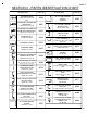
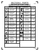
SECTION II - PARTS IDENTIFICATION CHART DESCRIPTION PART NO. STANDARD HEAD USE W/ 8314, 8326, FT46, FT47 STANDARD INTERMEDIATE HORIZONTAL 8300 8301 STANDARD SILL STANDARD SUBSILL 90˚ OUTSIDE CORNER MULLION HALF 8302 90˚ OUTSIDE CORNER SNAP IN FILLER USE W/ 8310, 8324 8344 2G22 1" GLASS STOP FOR HEAD & INT. HORIZONTAL USE W/ 8300, 8301, 8327, 8329, 8338, 8341 8307 8315 8303 8308 C.O.C.
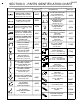
PAGE 3 SECTION II - PARTS IDENTIFICATION CHART DESCRIPTION TWO COLOR / STRUCT. GLAZED FACE COVER PART NO. 8335 USE W/ 8329, 8338, 8339, 8343 TWO COLOR / STRUCT. GLAZED FACE COVER 8336 USE W/ 8337, 8340, 8341 STRUCT. GLAZED / TWO COLOR STANDARD HEAD USE W/ 8314, 8326, 8335, FT46, FT47 STRUCT. GLAZED / TWO COLOR INT. HORIZONTAL 8338 8341 8337 8343 8339 8340 8465 1/4" GLAZING ADAPTER FOR DEEP POCKET 90˚ S.S.G.
SECTION II - PARTS IDENTIFICATION CHART DESCRIPTION PART NO. CAPTURED VERTICAL FILLER / MULLION DRILL FIXTURE DJ04 STRUCTURAL GLAZED VERTICAL FILLER / MULLION DRILL FIXTURE DJ05 DESCRIPTION S.S.G. TEMPORARY RETAINER USED W/ SSG MULLIONS SPACER SHIM FOR DORMA R.T.S. 88 CONCEALED OVERHEAD CLOSURE PAGE 4 PART NO. HGR1 FT71 #12-14 X 1 1/4" PL-PH-SMS 18-8 TYPE 25 STC8 1/2" ANTIWALK BLOCK HN50 ASSEMBLY SCREW EXTERIOR GLAZING GASKET FOR INSIDE GLAZED WC12 #10-16 X 1" PL-PH-SMS SG TEK 3 SLQ8 S.
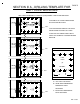
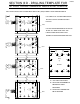
SECTION III A - DRILLING TEMPLATE FOR CAPTURED MULLIONS PAGE 5 LEFT HAND STANDARD INT. VERTICAL (8308) SHOWN. RIGHT HAND OPPOSITE. AC A USE SIDE #2 OF JIG FOR FABRICATION B OF CAPTURED MULLIONS. F945 (2) DJO4 #2 DRILL B BC 8300 USE THE INTERIOR SIDE OF THE GLASS A C LH C BC RH AC POCKET EDGE TO ALIGN JIG. MAKE SURE THAT THE FABRICATION HOLES ARE IN THE CORRECT POSITION BEFORE DRILLING.
PAGE 6 SECTION III B - DRILLING TEMPLATE FOR CAPTURED MULLION FILLERS LEFT HAND MULLION FILLER (8309) SHOWN. RIGHT HAND OPPOSITE. C A B USE SIDE #1 OF JIG FOR FABRICATION F945 DJO4 (1) #2 DRILL OF CAPTURED MULLION FILLERS. LH RH AC BC 8300 USE THE EXTERIOR EDGE OF FILLER TO B BC A C AC ALIGN JIG. MAKE SURE THAT THE FABRICATION HOLES ARE IN THE CORRECT POSITION BEFORE DRILLING.
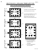
SECTION III C - DRILLING TEMPLATE FOR STRUCTURAL GLAZED MULLIONS PAGE 7 LEFT HAND STRUCTURAL GLAZED MULLION (8320) SHOWN. RIGHT HAND OPPOSITE. C AC LH USE SIDE #4 OF JIG FOR FABRICATION A BC OF STRUCTURAL GLAZED MULLIONS. B F945 (4) DJ05 #2 DRILL 8300 BC B USE THE EXTERIOR EDGE TO ALIGN JIG. AC A MAKE SURE THAT THE FABRICATION C RH HOLES ARE IN THE CORRECT POSITION BEFORE DRILLING.
SECTION III D - DRILLING TEMPLATE FOR STRUCTURAL GLAZED MULLION FILLERS PAGE 8 LEFT HAND STRUCTURAL GLAZED MULLION FILLER (8309) SHOWN. RIGHT HAND OPPOSITE. USE SIDE #3 OF JIG FOR FABRICATION C A BC B OF STRUCTURAL GLAZED MULLION LH F945 (3) DJ05 #2 DRILL FILLERS. 8300 RH AC USE THE EXTERIOR EDGE OF FILLER TO BC B AC A C ALIGN JIG. MAKE SURE THAT THE FABRICATION HOLES ARE IN THE CORRECT POSITION BEFORE DRILLING.
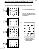
PAGE 9 SECTION IV - UNIT ASSEMBLY INCLUDES CAPTURED AND STRUCTURAL GLAZED MULLION SYSTEMS STEP 1) GENERAL NOTES A. Ensure that all tooling is correct before assembly. For each D.L.O. there should be a deep pocket and a shallow pocket. If only one D.L.O. is required, both pockets will be deep. The glass will not be able to be loaded with two shallow pockets. Also, keep all deep pockets on center D.L.O.'s on the same side of the D.L.O. See Fig. 1 below. JAMB VERT. EXPANSION MULLION VERT.
SECTION IV - UNIT ASSEMBLY (CON’T) PAGE 10 CAPTURED MULLION SYSTEMS STEP 2) HORIZONTALS TO JAMB ASSEMBLY HEAD ANCHOR (8300) FT46 (SHOWN) FT47 (OPTION) JAMB (8307) APPLY BUTYL TYPE SEALANT TO THE END OF ALL THE HORIZONTALS BEFORE ATTACHING TO THE JAMBS. HEAD ANCHOR (8300) FT46 (SHOWN) FT47 (OPTION) JAMB (8307) INT. HORIZONTAL 8301 - STANDARD (8302 - OPTIONAL) SILL (8344) VERT. MULLION FILLER (8309) STC8 VERTICAL INT. 8308 INT.
SECTION IV - UNIT ASSEMBLY (CON’T) PAGE 11 CAPTURED AND STRUCTURAL GLAZED MULLION SYSTEMS STEP 3) HORIZONTALS TO EXPANSION MULLION ASSEMBLY (CAPTURED SYSTEM SHOWN, STRUCTURAL GLAZED SYSTEM SIMILAR) To ensure that the unit will assemble correctly, verify that the expansion mullion halves are fabricated opposite of each other. See Fig. 4. Apply butyl type sealant to the ends of all horizontal members that come in contact with the expansion mullion. Install anchors into the head.
SECTION IV - UNIT ASSEMBLY (CON’T) PAGE 12 STRUCTURAL GLAZED MULLION SYSTEMS STEP 4) STRUCTURAL GLAZED SYSTEM ASSEMBLY To ensure that the unit will assemble correctly, verify that the structural glazed mullion and filler are fabricated opposite of each other. Apply butyl type sealant to the end of all horizontal members that come into contact with the structural glazed mullion. Install anchors into the head. Before assembly, apply wax lubricant to all STC8 fasteners.
PAGE 13 SECTION V - SUBSILL FABRICATION INCLUDES CAPTURED AND STRUCTURAL GLAZED MULLION SYSTEMS STEP 1) CUT LENGTH Measure the opening to determine the cut length of the subsill. Subtract 1/4" for the width of the end dam and fastener head from the rough opening for each end. Cut the subsill to the determined length. CUT LENGTH = R.O. - 1/2" K458 END DAM +1/8" -0 ROUGH OPENING SUBSILL 2G22 1/4" 1/4" ROUGH OPENING - 1/2" [FIG.
PAGE 14 SECTION V - SUBSILL FABRICATION (CON'T) INCLUDES CAPTURED AND STRUCTURAL GLAZED MULLION SYSTEMS STEP 3) BAFFLE FABRICATION Weep baffles are cut from (1) HCW6, halved. This provides (2) weep baffles per HCW6. See Fig. 8 below. " 3/8 " 1/2 " 3/4 " 1/2 2" 2" HCW6 [FIG. 8] STEP 4) WEEP BAFFLE INSTALLATION Apply a small amount of silicone type sealant to the baffles, and locate them over the weep holes.
SECTION V - SUBSILL FABRICATION (CON’T) PAGE 15 INCLUDES CAPTURED AND STRUCTURAL GLAZED MULLION SYSTEMS STEP 5) END DAM INSTALLATION The end dam is to be attached to the subsill with 2 SLQ1 fasteners on each end. Seal the end of the subsill with silicone sealant before attaching the end dam to the subsill. Tool the sealant at the interior joint of the end dam to ensure a good watertight seal. See Figure 10 below.
SECTION V - SUBSILL FABRICATION (CON’T) PAGE 16 INCLUDES CAPTURED AND STRUCTURAL GLAZED MULLION SYSTEMS STEP 7) SEALANT BED Apply sealant to the subsill as shown in Figure 11. Place the subsill into the rough opening, and rotate the exterior face down into position. Apply enough sealant to ensure a complete seal as shown in Figure 12. SUBSILL SEALANT 2G22 [FIG. 11] CONDITION SUBSILL 2G22 SUBSILL Wipe off any excess sealant from the exterior of the subsill. SEALANT 2G22 [FIG.
SECTION V - SUBSILL FABRICATION (CON’T) PAGE 17 INCLUDES CAPTURED AND STRUCTURAL GLAZED MULLION SYSTEMS STEP 8) SUBSILL ANCHOR INSTALLATION At a minimum, anchor at 6" from jambs and corners, (1) on each side of vertical mullions, and 24" O.C. between verticals. These are general guidelines. Size fasteners as required to meet structural loads. K473 HD ANCHOR 3/4" (OPTIONAL) (FASTENERS NOT SUPPLIED BY EFCO) 8308 3"± SUBSILL 2G22 [FIG. 13] [FIG.
SECTION V - SUBSILL FABRICATION (CON’T) PAGE 18 INCLUDES CAPTURED AND STRUCTURAL GLAZED MULLION SYSTEMS STEP 9) SUBSILL ANCHOR SEAL The subsill anchor must be sealed with a silicone type sealant. To ensure a good seal, tool the sealant onto the fastener. SILICONE TYPE SEALANT SUBSILL 2G22 [FIG. 15] STEP 10) SUBSILL PERIMETER SEAL The subsill interior should be sealed with a silicone type sealant. Apply sealant and tool the sealant to ensure a good seal. Clean off all excess sealant.
PAGE 19 SECTION V - SUBSILL FABRICATION (CON’T) INCLUDES CAPTURED AND STRUCTURAL GLAZED MULLION SYSTEMS STEP 11) SUBSILL SPLICING Verify that the subsill has been installed according to the instructions on Pages 9 through 14. Splice areas are to be centered at a vertical mullion only. Maximum subsill length between splices is 20’. If a splice is required, leave a 1/4" gap between the subsill ends at the splice area. Install and anchor the next run of subsill.
SECTION V - SUBSILL FABRICATION (CON’T) PAGE 20 INCLUDES CAPTURED AND STRUCTURAL GLAZED MULLION SYSTEMS STEP 12) SUBSILL CORNER MITER AND SPLICING When mitering the subsill for corner applications, cut the subsill material at the appropriate angle required to form the correct corner. Install the subsill by following the previous subsill installation instructions. Once the subsill is installed and a tight miter joint is achieved, use the instructions on Page 19 for creating a splice joint seal.
PAGE 21 SECTION VI - CORNERS CORNER IDENTIFICATION AND ASSEMBLY Proper identification of the required corner members is necessary to ensure a timely installation process. 1) 2) 3) 4) 5) 90˚ captured outside corner 90˚ captured inside corner 90˚ S.S.G. inside corner 90˚ S.S.G. outside corner 135˚ S.S.G. outside corner Determine that the subsill has been installed according to the instructions listed on Pages 13 through 20. Assemble the appropriate extrusions to create the required corner member.
PAGE 22 SECTION VI - CORNERS (cont.) CORNER IDENTIFICATION AND ASSEMBLY (CON’T) 8320 STC8 STT6 8309 EY83 WEP0 STC8 STT6 [FIG. 20] STT6 STT6 STC8 STC8 8320 WEP0 8309 8466 WEP0 [FIG. 21] STC8 STT6 8465 WEP0 2G69 STC8 8467 8309 STC8 8309 WEP0 WEP0 STC8 STC8 [FIG.
PAGE 23 SECTION VII - DOOR FRAME INSTALLATION STEP 1) GENERAL NOTES If a door opening is required, the subsill must be installed into the opening from the door framing, ensuring that the appropriate clearance is available for the door frame. All subsequent ladders must be installed from the door jamb out. INSTALL 1ST (AFTER SUBSILL) 1 3/16" 1 3/16" SUBFRAME CLEARANCE HOLE = [DOOR OPENING WIDTH + 2 3/8"] [FIG.
SECTION VII - DOOR FRAME INSTALLATION PAGE 24 (cont.) STEP 3) SUBSILL SEALANT AT DOOR FRAME Before installing the door frame to the subsill, seal the end of the subsill with a silicone type sealant. Install the door frame, and tool all excess sealant into the joint. If required, add more sealant to create a smooth water tight seal. DOOR FRAME 1/2 " SEALANT NOTCH FOR SUBSILL SUBSILL [FIG.
PAGE 25 SECTION VIII - INSTALLATION INCLUDES CAPTURED AND STRUCTURAL GLAZED MULLION SYSTEMS STEP 1) SEALING THE SILL ONTO THE SUBSILL Apply a silicone type sealant to the subsill in the location shown in Figure 24 before installing the first ladder. Make sure that enough sealant is applied to seal the areas shown in Figure 25. After installing the ladder and anchoring it, clean off all excess sealant. SEALANT 2G22 SEALANT [FIG. 24] 8344 2G22 SEALANT SEALANT [FIG.
SECTION VIII - INSTALLATION (CON’T) PAGE 26 INCLUDES CAPTURED AND STRUCTURAL GLAZED MULLION SYSTEMS STEP 2) INSTALLING JAMB SIDE LADDER Make sure that the anchors are installed into the head. Place the ladder on the subsill at an approximate 30˚ angle. While applying pressure upwards, rotate the ladder into the condition. See Figure 25 on Page 25 for sill placement into the subsill. When rotated correctly, the exterior face of the sill should be flush with the exterior face of the subsill.
PAGE 27 SECTION VIII - INSTALLATION (CON’T) INCLUDES CAPTURED AND STRUCTURAL GLAZED MULLION SYSTEMS STEP 3) ANCHORING THE HEAD For D.L.O.’s 36" and narrower, the anchors must be spaced 6" from the jamb or vertical members. For D.L.O.’s 36" and wider, the outside anchors must be spaced 6" from the jamb with the center anchor centered on the D.L.O. See Figure 28. If no strap anchor is used, anchor the head as shown in Figure 29, and use the same anchor spacing requirements.
SECTION VIII - INSTALLATION (CON’T) PAGE 28 INCLUDES CAPTURED AND STRUCTURAL GLAZED MULLION SYSTEMS STEP 4) ANCHORING THE JAMB Anchors must be spaced 6" from the sill or head, and 24" O.C. ± 4", so they do not interfere with the horizontal members. The size and type of anchors depend on 6" structural loads and surrounding condition. Anchors are not by EFCO. FD 24" ± 4" 8307 24" ± 4" FD REF 24" ± 4" 1/2" FD [FIG. 31] 6" FD [FIG.
SECTION VIII - INSTALLATION (CON’T) PAGE 29 INCLUDES CAPTURED AND STRUCTURAL GLAZED MULLION SYSTEMS STEP 5) SEALING THE EXPANSION MULLION If installing an expansion mullion, apply silicone type sealant in the locations shown below. The interior should be sealed up 6" from the subsill, and the entire exterior joint should be sealed. Apply enough sealant so that when the expansion mullion is collapsed, it will squeeze the sealant out and create a good seal. Clean off any excess sealant.
SECTION VIII - INSTALLATION (CON’T) PAGE 30 INCLUDES CAPTURED AND STRUCTURAL GLAZED MULLION SYSTEMS STEP 7) INSTALLING THE SECOND LADDER (CAPTURED SYSTEM SHOWN, STRUCTURAL GLAZED SYSTEM SIMILAR) Make sure that the anchors are installed into the head. Apply silicone type sealant to the interior leg clip 6" from the subsill, and seal the entire exterior face as shown in Figure 37. Apply sealant to the subsill as shown on Page 25. Place the second ladder on the subsill at an approximate 30˚ angle.
SECTION VIII - INSTALLATION (CON'T) PAGE 31 INCLUDES CAPTURED AND STRUCTURAL GLAZED MULLION SYSTEMS STEP 8) SNAPPING THE EXPANSION MULLION (CAPTURED SYSTEM SHOWN, STRUCTURAL GLAZED SYSTEM SIMILAR) To snap the expansion mullion together, line up the mullion halves and gaskets. See Figure 39. Place one clamp at the bottom of the expansion mullion using wood blocks to protect the extrusions. Tighten the C-clamp until the expansion mullion halves begin to snap together.
PAGE 32 SECTION VIII - INSTALLATION (CON'T) INCLUDES CAPTURED AND STRUCTURAL GLAZED MULLION SYSTEMS STEP 9) SNAPPING THE SNAP-IN FILLER To snap the snap-in filler, place the ladder in the subsill and align the snap-in filler with the intermediate vertical, ensuring that the ladders are as tight together as possible before continuing. Using a rubber mallet, gently tap the filler into place if necessary.
SECTION VIII - INSTALLATION (CON’T) PAGE 33 INCLUDES CAPTURED AND STRUCTURAL GLAZED MULLION SYSTEMS STEP 10) ANCHORING THE SECOND LADDER After the filler is snapped correctly, anchor the head and jamb as shown on Pages 27 and 28. STEP 11) PERIMETER SEAL When the unit is installed and anchored, begin placing caulk rope into the gap between the perimeter and the frame. Then apply a generous amount of silicone type sealant to the gap between the frame and rough opening.
PAGE 34 SECTION IX - GLAZING FOR INSIDE GLAZED CAPTURED FRAMING SYSTEMS STEP 1A) IDENTIFICATION OF GLASS POCKETS 1" GLAZING FOR INSIDE GLAZED CAPTURED FRAMING SYSTEM TYP. VERTICAL 1" GLASS W160 W160 1" GLASS W160 WC12 WC12 WC12 TYP. 1" GLASS STOP 1" GLASS TYP. HORIZONTAL WC12 W160 [FIG. 44] 1" GLASS 1/4" GLAZING FOR INSIDE GLAZED CAPTURED FRAMING SYSTEM TYP. VERTICAL W160 8324 8323 W160 1/4" GLASS 1/4" GLASS WC12 W160 8323 WC12 WC12 HDR6 TYP. 1/4" GLASS STOP 1/4" GLASS TYP.
PAGE 35 SECTION IX - GLAZING (cont.) FOR OUTSIDE GLAZED AND STRUCTURAL GLAZED FRAMING SYSTEMS STEP 1B) IDENTIFICATION OF GLASS POCKETS 1" GLAZING FOR OUTSIDE GLAZED AND STRUCTURAL SILICONE GLAZED FRAMING SYSTEM TYP. O.G. VERTICAL WNE0 WNE0 1" GLASS 1" GLASS TYP. WNE0 HORIZONTAL W160 W160 W160 1" GLASS TYP. 1" GLASS STOP TYP. FACE COVER TYP. FACE COVER WNE0 W160 [FIG. 46] 1" GLASS WNE0 TYP. JAMB W160 TYP. S.S.G. VERTICAL 1" GLASS WEP0 TYP. FACE COVER [FIG.
PAGE 36 SECTION IX - GLAZING (cont.) FOR OUTSIDE GLAZED AND STRUCTURAL GLAZED FRAMING SYSTEMS STEP 1C) IDENTIFICATION OF GLASS POCKETS 1/4" GLAZING FOR OUTSIDE GLAZED AND STRUCTURAL SILICONE GLAZED FRAMING SYSTEM TYP. O.G. VERTICAL TYP. HORIZONTAL WNE0 W160 WNE0 1/4" GLASS 8323 HDR6 W160 W160 WNE0 8323 8324 1/4" GLASS 1/4" GLASS TYP. 1/4" GLASS STOP TYP. FACE COVER TYP. FACE COVER W160 WNE0 [FIG. 48] 1/4" GLASS 8324 TYP. S.S.G. VERTICAL W160 WNE0 TYP. JAMB 1/4" GLASS TYP.
SECTION IX - GLAZING (cont.) PAGE 37 INCLUDES CAPTURED AND STRUCTURAL GLAZED MULLION SYSTEMS CUT LENGTH FOR ALL REMOVABLE GLASS STOPS = D.L.O. - 1/32" STEP 2) GLASS SIZE FORMULAS CAPTURED: GLASS SIZE = [D.L.O. + 7/8"] STRUCTURAL GLAZED: (TWO STRUCTURAL GLAZED MULLIONS) GLASS SIZE = [D.L.O. + 1 3/4"] (ONE STRUCTURAL GLAZED MULLION AND ONE CAPTURED MULLION) GLASS SIZE = [D.L.O. + 1 5/16"] ALL VERTICAL GLASS SIZES = [D.L.O. + 7/8"] CAPTURED 8307 STD.
SECTION IX - GLAZING (cont.) PAGE 38 INCLUDES CAPTURED AND STRUCTURAL GLAZED MULLION SYSTEMS STEP 3) INSTALLING THE WATER DEFLECTOR HWD1 - WATER DEFLECTOR TYP. JAMB/ VERTICAL TRIM THE HWD1 TO THE REQUIRED WIDTH. INSTALL AT THE ENDS OF INT. HORIZONTAL. USE A SILICONE TYPE SEALANT TO ADHERE HWD1 ONTO THE INT. HORIZONTAL. 8307 (SHOWN) 8301 (SHOWN) 8302 8337 (SHOWN) 8341 OUTSIDE OF DIE REMOVED FOR CLARITY. [FIG. 51] TYP. VERTICAL TYP.
SECTION IX - GLAZING (cont.) PAGE 39 INCLUDES CAPTURED AND STRUCTURAL GLAZED MULLION SYSTEMS STEP 4) APPLYING SEALANT AT GLAZING BEAD AND VERTICAL MULLION OUTSIDE GLAZE NOTE: THIS STEP MUST BE DONE TO ENSURE A WATERTIGHT SEAL AT THE INTERIOR OF THE UNIT AROUND THE HORIZONTAL GLAZING BEAD. AFTER GLAZING BEAD IS INSTALLED, RUN A BEAD OF SEALANT DOWN THE SEAM OF THE BEAD AND 1" UP THE GASKET RACE. TOOL THE SEALANT ALONG THE SEAM SO A WATERTIGHT SEAL IS MADE.
SECTION IX - GLAZING (cont.) PAGE 40 INCLUDES CAPTURED AND STRUCTURAL GLAZED MULLION SYSTEMS STEP 4) INSTALLING THE S.S.G. MULLION HORIZONTAL BRIDGE ASSEMBLY NOTE: USE THIS PROCEDURE WHERE THE STRUCTURAL GLAZED EXPANSION MULLION IS USED. 8308 8309 Press the bridge assembly into the sealant and apply a bead of sealant to the perimeter seam of the bridge. Tool into the horizontal and vertical to achieve a water seal at the bridge. 8341 8341 [FIG. 54] K483 [FIG.
SECTION IX - GLAZING (cont) PAGE 41 INCLUDES CAPTURED AND STRUCTURAL GLAZED MULLION SYSTEMS STEP 6A) GLASS INSTALLATION (INSIDE GLAZED) A) Make sure the setting blocks are placed at 1/4 points in each D.L.O. or as required on the architectural drawings. (See Figure 57) - For the following steps, use Figures 58 and 59. B) Position the glass on the interior of the framing without the removable stop installed. Shift the glass into the deep pocket to begin glass installation.
SECTION IX - GLAZING (cont.) PAGE 42 INCLUDES CAPTURED AND STRUCTURAL GLAZED MULLION SYSTEMS STEP 6B) GLASS INSTALLATION (OUTSIDE GLAZED) - For the following steps, use Figures 61 and 62. A) Make sure the setting blocks are placed at 1/4 points in each D.L.O. or as required on the architectural drawings. (See Figure 57 on Page 41) B) Position the glass at the exterior of the framing with all the face covers removed. Lift the glass into the frame and onto the setting blocks.
SECTION IX - GLAZING (cont.) PAGE 43 INCLUDES CAPTURED AND STRUCTURAL GLAZED MULLION SYSTEMS STEP 6C) GLASS INSTALLATION (STRUCTURAL GLAZED) - For the following steps, use Figures 64 and 65. A) Make sure the setting blocks are placed at 1/4 points in each D.L.O. or as required on the architectural drawings. (See Figure 57 on Page 41) B) Position the glass at the exterior of the framing with the head and sill face covers removed. Lift the glass into the frame and onto the setting blocks.
SECTION IX - GLAZING (cont.) PAGE 44 STEP 7) FACE COVER SPLICING Splicing of the head and sill face covers can be accomplished at any place along the horizontal span. Splicing of the intermediate horizontal face covers must be done at the center line of a vertical mullion. Ensure that the face cover end cuts are square, clean of burrs or sharp edges, and clean of all cutting oils or other contaminants. Space the face covers 1/4" apart at the required splice area.
SECTION IX - GLAZING (cont.) PAGE 45 INCLUDES CAPTURED AND STRUCTURAL GLAZED MULLION SYSTEMS STEP 8) INSTALLATION OF GLAZING GASKET INSIDE GLAZED Install W160 gasket at the vertical members. See note below. Install W160 gasket into the horizontal members so they fit tightly into the vertical gaskets. (D.L.O. + 2%) OUTSIDE GLAZED Install W160 gasket at the vertical members. See note below. Install W160 gasket into the horizontal members so they fit tightly into the vertical gaskets. (D.L.O.
SECTION IX - GLAZING (cont.) PAGE 46 STRUCTURAL GLAZED MULLION SYSTEMS STEP 9) FILLING THE STRUCTURAL GLAZING GAP - THIS PROCEDURE APPLIES TO THE STANDARD STRUCTURAL GLAZED VERTICAL AND THE STRUCTURAL GLAZED EXPANSION MULLION. After the interior sealant has cured, typically an overnight setup is required. Mask off the glass edges with masking tape to minimize cleanup and provide a professional appearance.
SECTION X - DOOR FRAMES PAGE 47 STEP 1) DOOR STOP CUT LENGTH AND INSTALLATION DOOR STOP Install the applied door stop into position on the door frame by spacing it off the exterior face of the door frame at the appropriate dimension, depending on door thickness. Using STT6 fasteners, 3" from each end and 12" O.C., fasten the door stop to the door jamb and door header. After determining that the door stop is in the correct position, apply the door stop cover by snapping it into the door stop raceway.
SECTION X - DOOR FRAMES (con't) PAGE 48 STEP 2) TRANSOM GLASS STOP CUT LENGTH AND INSTALLATION TRANSOM LITE GLASS STOP Install the transom lite glass stop with the long glass stop leg flush to the exterior of the door framing at the transom area. Use a silicone type sealant the full perimeter of the transom lite glass stop in the sealant raceway and at the ends to provide a water tight seal. Make sure that all horizontal members run through. This will ensure that a water dam is established.